1989 MITSUBISHI GALANT kickdown
[x] Cancel search: kickdownPage 742 of 1273
23-36AUTOMATIC TRANSAXLE
- Troubleshooting
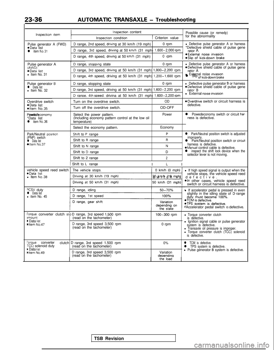
Inspectron ItemInspection content
Inspectron condrtion
Possible cause (or remedy)
1 Criterion valuefor the abnormality
Pulse generator A (FWD)D range, 2nd speed, drivrng at 30 km/h (19 mph)
0 rpml Defective pulse generator A or harness*Data
list *Defective shield cable of pulse gene
l item No.31D range, 3rd speed, drivrng at 50 km/h (31 mph) 1.600-2.000
rpmrafnr A
D range, 4th speed, driving at 50 km/h (31 mph)n
Pulse generator AW’J’JD) *Data
lrstl Item No. 31
D range, stopprng state 0 rpml Defective pulse generator A or harness *Defective
shield cable of pulse gene
D range, 3rd speed, drivrng at 50 km/h (31 mph) 1.800-2.200
rpmrator A
D range, 4th speed, driving at 50 km/h (31 mph) 1.200-1.600
rpml External noise rnvasronl Slip of kickdown brake
Pulse generator Bl Data listl Item No. 32
D range, stopping state 0 rpml Defective pulse generator B or harness
D range, 3rd speed, driving at 50 km/h (31 mph) 1.600-2.200
rpm *Defective
shield cable of pulse generator B
D ranoe. 4th soeed. drivina at 50 km/h (31 mph) 1.600-2.200
mml External noise invasron
Overdrive switch *Data
list
*Item No.35
Turn on the overdrive switch.
Turn off the overdrive switch.OD
OD-OFF
moverdrive switch or circuit harness isdefective. Power/economy switch
*Data list
l item No.36
Select the power pattern.
(Including economy pattern control at the low oil
temperature) Power
l Powedeconomy switch or circuit har-ness is defective.
Park/Neutral posrtion
(PNP) switch
l Data list*Item No.37
Select the economy pattern.
Shaft to P range
Shift to
R range
Shift to
N range
Shift to
D range
Shift to 2 ranqe
Economy
Pl Park/Neutral position switch is adjusted
improperly.
Rl Park/Neutral position switch or circuil
Nharness is defective.aManual control cable is defective.Dl inspect the shift lock device when theselector lever is not moving.2
1 Shift to L ranqe
I L I
vehicle speed reed switch *Data
lrstl Item No.38
0 km/h (0 mph)
-1
l If high speed signal is output when thevehicle stops, the vehicle speed reed
switch is defective
.
*In other cases, vehicle speed reed
switch or circuit harness is defective.
=CSV dutyl Data listl item No. 45
l If accelerator pedal is pressed in evenslightly in the idling state ofD range
*Accelerator pedal switch IS defective.
rorque converter clutch slrp D range, 3rd speed 1,500 rpmamount(read on the tachometer)m Data listmltem No.47D range, 3rd speed 3,500 rpm
(read on the tachometer) 100-300
rpm
0 rpm
l Torque converter clutch
is defective.
l Ignition signal cable or pulse generatorsystem is defective.l Transaxle oil pressure is improper.l Torque converter clutch (TCC) solenoid
is defective.
rorque converterclutch D range, 3rd speed 1.500 rpm0%l TCM is defective.TCC) solenoid duty(read on the tachometer)) Data listl TPS system is defective.
Dltem No.49D range, 3rd speed 3,500 rpmVariationl Pulse generator B system is defective.
(read on the tachometer)deoendina
TSB Revision
Page 743 of 1273
AUTOMATIC TRANSAXLE - Troubleshooting23-37
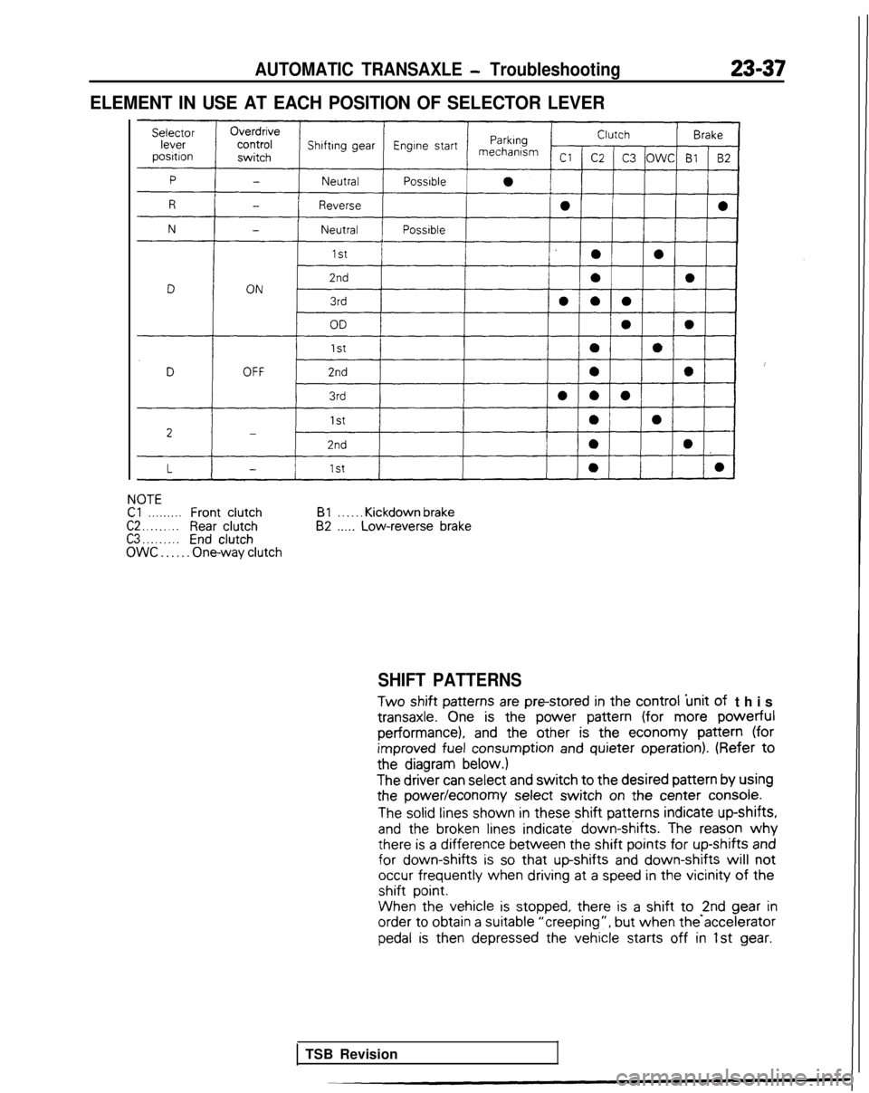
ELEMENT IN USE AT EACH POSITION OF SELECTOR LEVER
NOTECl. . . . . . . . .FrontclutchC2 . . . . . . . . .Rear clutchC3 . . . . . . . . .EndclutchOWC . . . . . . One-way clutchBl
. . . . . . Kickdown brake82 .._.. Low-reverse brake
SHIFT PATTERNS
Two
shift patterns
are pm-stored
in the
control
‘unit of
this transaxle.
One is the
power
pattern
(for more powerful
performance), and
the
other
is the
economy
pattern
(for
improved
fuel consumption
and quieter
operation).
(Refer to
the
diagram below.)
The
driver
can select
and switch to the
desired
pattern
by
using
the
power/economy
select
switch on the
center
console.
The solid lines
shown
in these
shift patterns
indicate
up-shifts,
and
the
broken lines indicate. down-shifts. The reason why there
is a difference
between
the
shift points for
up-shifts
and for
down-shifts is so that up-shifts
and down-shifts will not
occur frequently
when
driving
at
a speed in the
vicinity of the
shift
point.
When the
vehicle
is stopped,
there
is a shift to -2nd gear
in order
to
obtain
a suitable
“creeping”, but
when the accelerator
pedal is
then
depressed
the
vehicle
starts
off in 1st gear.
TSB Revision
Page 757 of 1273
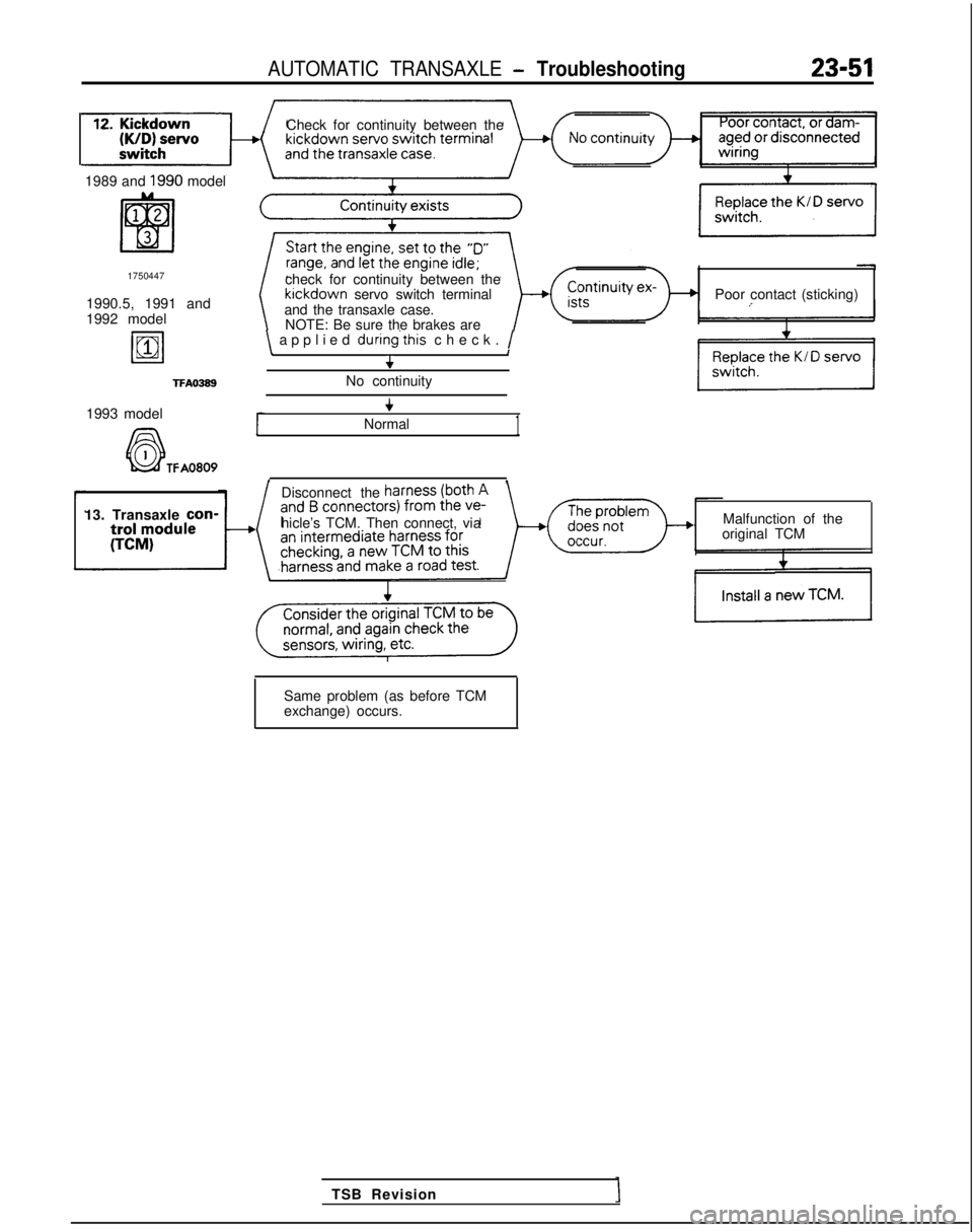
AUTOMATIC TRANSAXLE - Troubleshooting23-51
Check for continuity between the
1989 and
1990 model
1750447
1990.5, 1991 and
1992 model
19811
TFAO389
check for continuity between the kickdown
servo switch terminal
and the transaxle case. Poor contact (sticking)
NOTE: Be sure the brakes are
\ applied during’this
check. /\I+
No continuity
1993 model
A6-l
+
Normal1
k&f TFA0809, ,
Disconnect the
13. Transaxle con-
hicle’s TCM. Then connect, via Malfunction of the
original TCM
TSB Revision
Same problem (as before TCM
exchange) occurs.
Page 760 of 1273
23-54AUTOMATIC TRANSAXLE - Troubleshooting
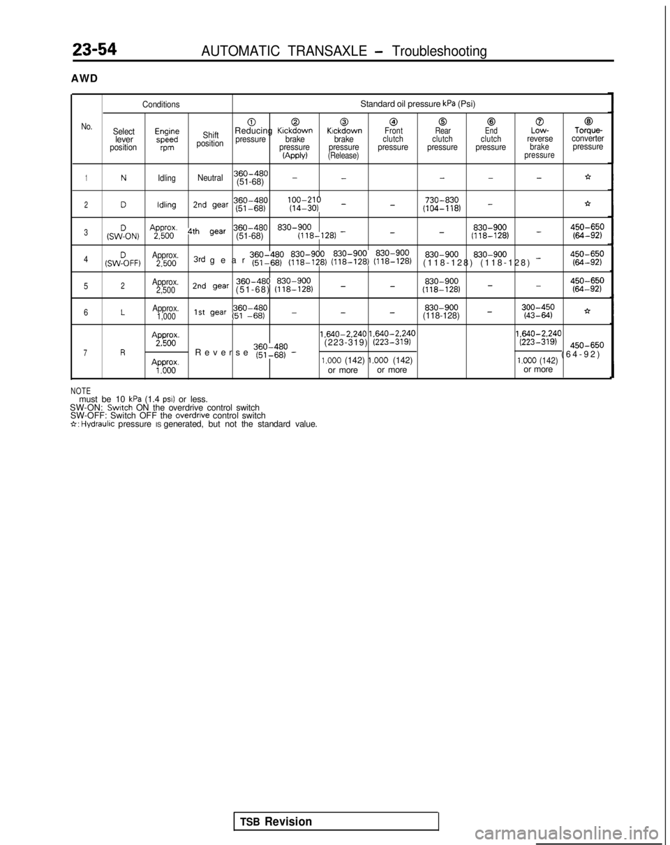
AWD
ConditionsStandard oil pressure kPa (Psi)
000@0@0@
No.Selectm;;ShiftReducing KickdownKickdownFront RearEndLow-Torque-leverpressurebrake brakeclutch clutch clutchreverseconverter
positionvmposition pressure pressure pressure pressure pressurebrakepressure(Apply)(Release)
pressure
1NIdlingNeutral360-480---*(51-68) --
360-480 lfyfI;;; _ 730-8302Dldlrng2nd war (51-68)
(104-118) -*-
(sw!oN)
AgFil’ 4th gear360-480 830-900 830-900
_3--(51-68)
(118-128)
-(118-128)g:gp 830-900
4(SW%FF)Approx. 830-9002.5003rd gear ~~~I$p (y$$zr (~$$EJ (??i??$)(118-128) (118-128) -g::;p
Approx.2nd gear 360-480 830-900
830-900450-650-52(51-68)
(118-128) _-2,500
(118-128) - (64-92)
6LApprox.360-480
830-9001,0001st gear (51 -66)---(118-128) -;:;I$;*
Ap&;.
1.640-2.240
1.640-2.240 1.640-2.240
7R ’Reverse ~~~$~p -(223-319)
(223-319)(223-319) @O-65,,
(64-92
)
Ap”do”o”.1.000 (142) 1.000 (142)1.000 (142)or more
or more or more
NOTEmust be 10 kPa (1.4 PSI) or less.
SW-ON: Switch ON the overdrive control switch
SW-OFF: Switch OFF the overdrrve control switch6: Hydraulrc pressure IS generated, but not the standard value.
TSB Revision
Page 761 of 1273
AUTOMATIC TRANSAXLE - Troubleshooting23-55
Remedial Steps If Oil Pressure Is Not Normal
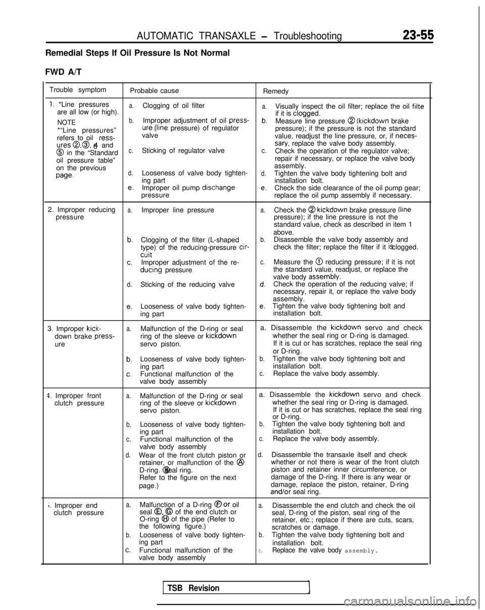
FWD A/T Trouble symptom Probable cause Remedy
1. *Line pressuresa.
a.are all low (or high).Clogging of oil filter
Visually inspect the oil filter; replace the oil filte
NOTEb.Improper adjustment of oil press-
if it is cl,ogged.b.Measure line pressure @ (kickdown
brake
*“Line pressures” ure,(line
pressure) of regulator
pressure); if the pressure is not the standard
refers to oil ress-
valve
value, readjust the line pressure, or, if neces-
ures@,@, 4 and
6sary, replace the valve body assembly. @
in the “Standardc.Sticking of regulator valvec.Check the operation of the regulator valve;
oil pressure table” repair if necessary, or replace the valve body
on the previous assembly.
wed.Looseness of valve body tighten-d.Tighten the valve body tightening bolt and
ing part installation bolt.
e.Improper oil pump dischangee.Check the side clearance of the oil pump gear;
pressure replace the oil pump assembly if necessary.
2. Improper reducing
a.Improper line pressurea.Check the @ kickdown
brake pressure /line
pressure pressure); if the line pressure is not the
standard value, check as described in item 1
above.
b.Clogging of the filter (L-shapedb.Disassemble the valve body assembly and
type) of the reducing-pressure cir-
check the filter; replace the filter if it is clogged.
cuitc.Improper adjustment of the re-c.Measure the @ reducing pressure; if it is not
ducing
pressure the standard value, readjust, or replace the
valve body assembly.
d.Sticking of the reducing valved.Check the operation of the reducing valve; if
necessary, repair it, or replace the valve body
assembly.
e.Looseness of valve body tighten-e.Tighten the valve body tightening bolt and
ing part installation bolt.
3. Improper
kick-a.Malfunction of the D-ring or seal a. Disassemble the kickdown
servo and check
down brake press-
ring of the sleeve or kickdown
whether the seal ring or D-ring is damaged.
ure servo piston. If it is cut or has scratches, replace the seal ring
or D-ring.
b.Looseness of valve body tighten-b.Tighten the valve body tightening bolt and
ing part installation bolt.
c.Functional malfunction of thec.Replace the valve body assembly.
valve body assembly
1. Improper front clutch pressurea.Malfunction of the D-ring or seal a. Disassemble the kickdown
servo and check
ring of the sleeve or kickdown
whether the seal ring or D-ring is damaged.
servo piston. If it is cut or has scratches, replace the seal ring
or D-ring.
b.Looseness of valve body tighten-b.Tighten the valve body tightening bolt and
ing part installation bolt.
c.Functional malfunction of thec.Replace the valve body assembly.
valve body assembly
d.Wear of the front clutch piston ord.Disassemble the transaxle itself and check
retainer, or malfunction of the @
whether or not there is wear of the front clutch
D-ring. @ seal ring.
piston and retainer inner circumference, or
Refer to the figure on the next damage of the D-ring. If there is any wear or
page.) damage, replace the piston, retainer, D-ring and/or
seal ring.
i. Improper end
clutch pressurea.Malfunction of a D-ring @or oila.Disassemble the end clutch and check the oil
seal 0.0 of the end clutch or
O-ring 8 of the pipe (Refer to seal, D-ring of the piston, seal ring of the
the following figure.) retainer, etc.; replace if there are cuts, scars,
scratches or damage.
b.Looseness of valve body tighten-b.Tighten the valve body tightening bolt and
ing part installation bolt.
c.Functional malfunction of thec.Replace the valve body assembly.valve body assembly
TSB Revision
Page 763 of 1273
AUTOMATIC TRANSAXLE - Troubleshootinn
23-57
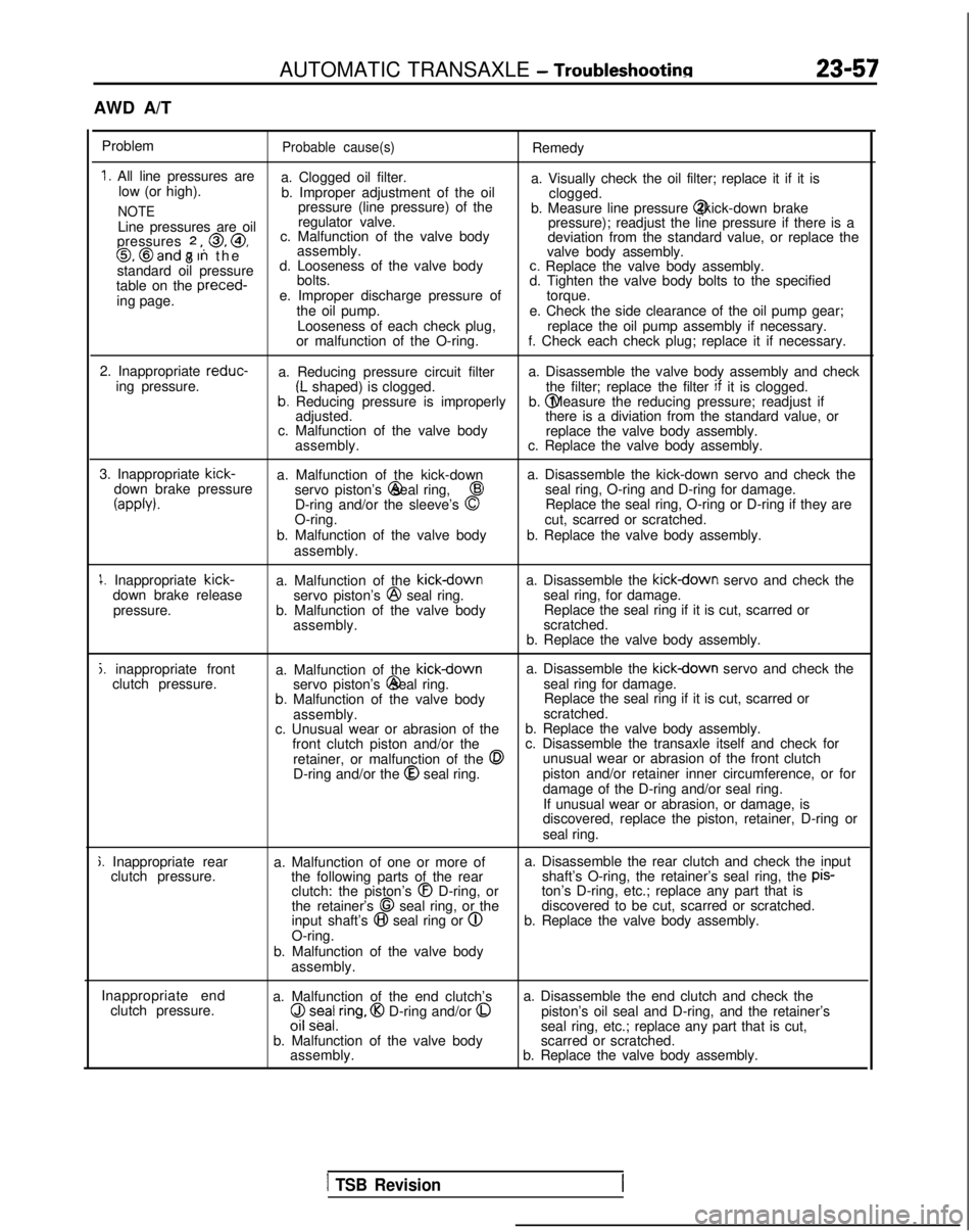
AWD A/T
Problem
Probable cause(s)Remedy
1. All line pressures are a. Clogged oil filter.
low (or high). a. Visually check the oil filter; replace it if it is
b. Improper adjustment of the oil clogged.
NOTEpressure (line pressure) of the
b. Measure line pressure @ (kick-down brake
Line pressures are oil regulator valve.
pressure); readjust the line pressure if there is a
pressures
2 ,, 0, @,
8 c. Malfunction of the valve body
deviation from the standard value, or replace the0, @and 7 In th
e
assembly.
valve body assembly.
standard oil pressure d. Looseness of the valve body
c. Replace the valve body assembly.
table on the preced-
bolts.
d. Tighten the valve body bolts to the specified
ing page. e. Improper discharge pressure of
torque.
the oil pump. e. Check the side clearance of the oil pump gear;
Looseness of each check plug, replace the oil pump assembly if necessary.
or malfunction of the O-ring. f. Check each check plug; replace it if necessary.
2. Inappropriate reduc-
a. Reducing pressure circuit filter a. Disassemble the valve body assembly and check
ing pressure.
(L shaped) is clogged. the filter; replace the filter if
it is clogged.b. Reducing pressure is improperly b. @ Measure the reducing pressure; readjust if
adjusted. there is a diviation from the standard value, or
c. Malfunction of the valve body replace the valve body assembly.
assembly. c. Replace the valve body assembly.
3. Inappropriate kick-
a. Malfunction of the kick-down a. Disassemble the kick-down servo and check the
down brake pressure servo piston’s @ seal ring,
43seal ring, O-ring and D-ring for damage.
(appb).D-ring and/or the sleeve’s 0Replace the seal ring, O-ring or D-ring if they are
O-ring. cut, scarred or scratched.
b. Malfunction of the valve body b. Replace the valve body assembly.
assembly.
1. Inappropriate kick-
down brake release
pressure. a. Malfunction of the kickdownservo piston’s @
seal ring.
b. Malfunction of the valve body assembly. a. Disassemble the kickdown servo and check the
seal ring, for damage. Replace the seal ring if it is cut, scarred or
scratched.
b. Replace the valve body assembly.
j. inappropriate front clutch pressure. a. Malfunction of the kickdowna. Disassemble the kickdown servo and check the
servo piston’s @ seal ring.
seal ring for damage.
b. Malfunction of the valve body Replace the seal ring if it is cut, scarred or
assembly. scratched.
c. Unusual wear or abrasion of the b. Replace the valve body assembly.
front clutch piston and/or the c. Disassemble the transaxle itself and check for
retainer, or malfunction of the
0unusual wear or abrasion of the front clutch
D-ring and/or the @
seal ring. piston and/or retainer inner circumference, or for
damage of the D-ring and/or seal ring.
If unusual wear or abrasion, or damage, is
discovered, replace the piston, retainer, D-ring or
seal ring.
j. Inappropriate rear clutch pressure. a. Malfunction of one or more of
the following parts of the rearclutch: the piston’s
@I D-ring, or
the retainer’s 68 seal ring, or the
input shaft’s @I seal ring or @
O-ring.
b. Malfunction of the valve body assembly. a. Disassemble the rear clutch and check the input
shaft’s O-ring, the retainer’s seal ring, the pis-
ton’s D-ring, etc.; replace any part that is
discovered to be cut, scarred or scratched.
b. Replace the valve body assembly.
Inappropriate end clutch pressure. a. Malfunction of the end clutch’s
($ z;ea/,ring, @I D-ring and/or 0
b. Malfunction of the valve body
assembly. a. Disassemble the end clutch and check the
piston’s oil seal and D-ring, and the retainer’s
seal ring, etc.; replace any part that is cut,
scarred or scratched.
b. Replace the valve body assembly.
1 TSB Revision
Page 784 of 1273
AUTOMATIC TRANSAXLE - Troubleshooting
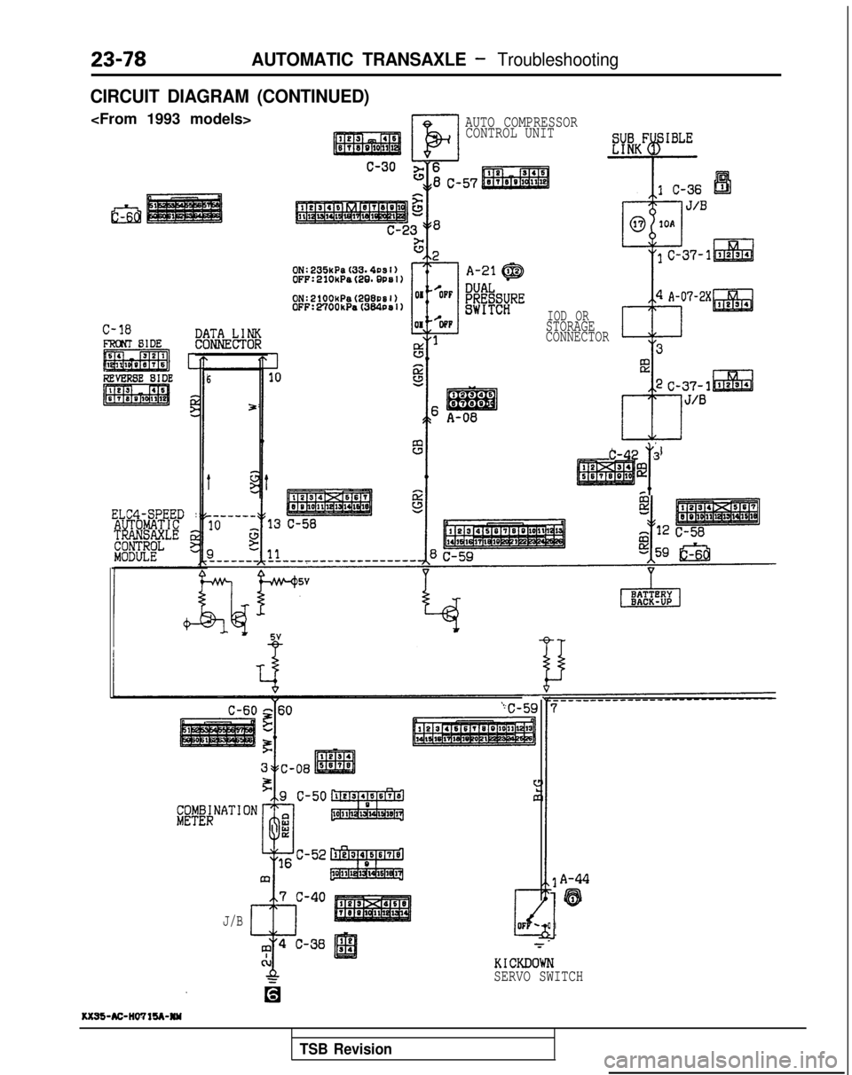
CIRCUIT DIAGRAM (CONTINUED)
El
AUTO COMPRESSORCONTROL UNIT
C-18
ELC4-SPEED :
6
5
J/B IOD OR
STORAGE
CONNECTOR
T
C-42 3
@
I
A-44
'63
1
KICKDOWN
SERVO SWITCH
1(x95-AC-IlWlU-NW
TSB Revision
Page 792 of 1273
23-86AUTOMATIC TRANSAXLE -Service Adjustment Procedures
09A0179control lever
control lever
5 mm
Section A-A i.2 in.)Manual
Switch body
175133
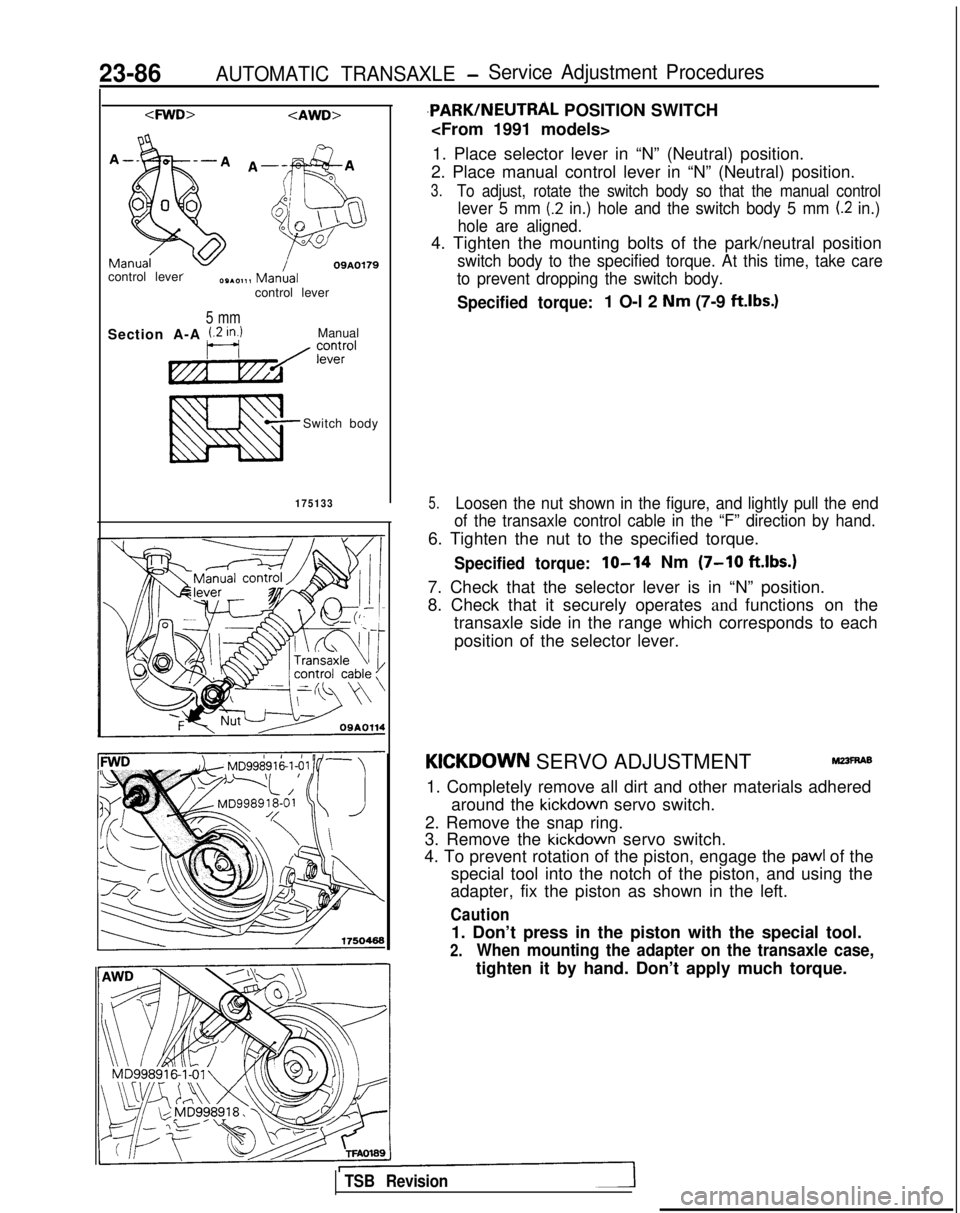
,PARK/NEUTRAL POSITION SWITCH
1. Place selector lever in “N” (Neutral) position.
2. Place manual control lever in “N” (Neutral) position.
3.To adjust, rotate the switch body so that the manual control
lever 5 mm (.2 in.) hole and the switch body 5 mm (.2 in.)
hole are aligned.
4. Tighten the mounting bolts of the park/neutral position
switch body to the specified torque. At this time, take care
to prevent dropping the switch body.
Specified torque:1 O-l 2 Nm (7-9 ftlbs.)
5.Loosen the nut shown in the figure, and lightly pull the end
of the transaxle control cable in the “F” direction by hand.
6. Tighten the nut to the specified torque.
Specified torque:lo-14 Nm (7-10 ft.lbs.1
7. Check that the selector lever is in “N” position.
8. Check that it securely operates and functions on the
transaxle side in the range which corresponds to each
position of the selector lever.
KICKDOWN SERVO ADJUSTMENTr&?3~6
1. Completely remove all dirt and other materials adhered around the
kickdown servo switch.
2. Remove the snap ring.
3. Remove the
kickdown servo switch.
4. To prevent rotation of the piston, engage the
pawl of the
special tool into the notch of the piston, and using the
adapter, fix the piston as shown in the left.
Caution
1. Don’t press in the piston with the special tool.
2.When mounting the adapter on the transaxle case,
tighten it by hand. Don’t apply much torque.
TSB Revision