1989 MITSUBISHI GALANT bulb
[x] Cancel search: bulbPage 152 of 1273
13-10
FUEL SYSTEM
at sensor side
1\~“‘,““W,O,’ ‘\*N 4-cnDQ5a,, \llllf,,
c 3 c-11 ‘.<-!
( .[&
;%* \ g ~ &.$$~&%,;
0%: E
.Oj-,,
giI lOWI -,n
/ ~ ( ~~‘-~~~
-.mo .u. m,.0 - rj*> ;;
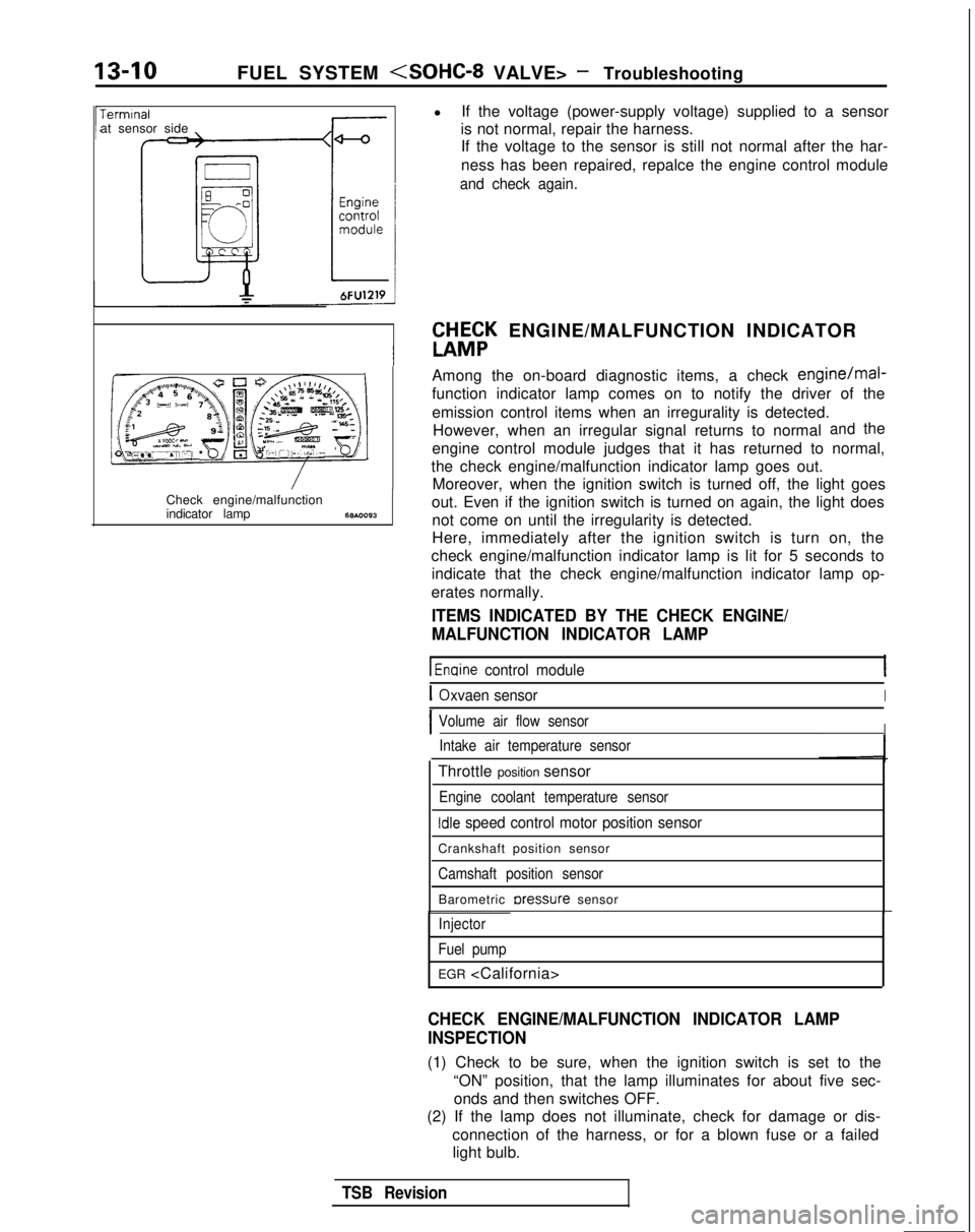
indicator lamp68AOO93
l
If the voltage (power-supply voltage) supplied to a sensor
is not normal, repair the harness. If the voltage to the sensor is still not normal after the har-
ness has been repaired, repalce the engine control module
and check again.
W&K ENGINE/MALFUNCTION INDICATOR
Among the on-board diagnostic items, a check
engine/mal-
function indicator lamp comes on to notify the driver of the
emission control items when an irregurality is detected. However, when an irregular signal returns to normal
andthe
engine control module judges that it has returned to normal,
the check engine/malfunction indicator lamp goes out. Moreover, when the ignition switch is turned off, the light goes
out. Even if the ignition switch is turned on again, the light does not come on until the irregularity is detected.
Here, immediately after the ignition switch is turn on, the
check engine/malfunction indicator lamp is lit for 5 seconds to indicate that the check engine/malfunction indicator lamp op-
erates normally.
ITEMS INDICATED BY THE CHECK ENGINE/
MALFUNCTION INDICATOR LAMP
1 Enaine control module
IOxvaen sensorI
IVolume air flow sensorIIntake air temperature sensor
Throttle position sensor
Engine coolant temperature sensor
Idle speed control motor position sensor
Crankshaft position sensor
Camshaft position sensor
Barometric rxessure sensor
Injector
Fuel pump
EGR
CHECK ENGINE/MALFUNCTION INDICATOR LAMP
INSPECTION
(1) Check to be sure, when the ignition switch is set to the “ON” position, that the lamp illuminates for about five sec-onds and then switches OFF.
(2) If the lamp does not illuminate, check for damage or dis-
connection of the harness, or for a blown fuse or a failedlight bulb.
TSB Revision
Page 262 of 1273
13-120FUEL SYSTEM
CHH;K
ENGINE/MALFUNCTION INDICATOR
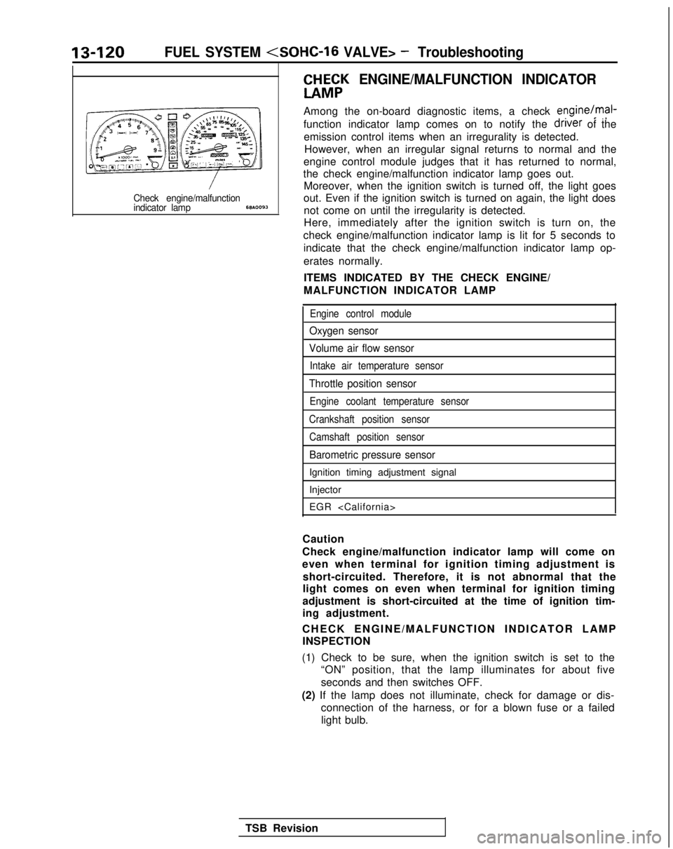
Among the on-board diagnostic items, a check engine/mal-
function indicator lamp comes on to notify the driver
of the
emission control items when an irregurality is detected. However, when an irregular signal returns to normal and the
engine control module judges that it has returned to normal,
the check engine/malfunction indicator lamp goes out. Moreover, when the ignition switch is turned off, the light goes
Check engine/malfunctionout. Even if the ignition switch is turned on again, the light doesindicator lamp68A.0093not come on until the irregularity is detected.
Here, immediately after the ignition switch is turn on, the
check engine/malfunction indicator lamp is lit for 5 seconds to indicate that the check engine/malfunction indicator lamp op-
erates normally.
ITEMS INDICATED BY THE CHECK ENGINE/
MALFUNCTION INDICATOR LAMP
Engine control module
Oxygen sensor
Volume air flow sensor
Intake air temperature sensor
Throttle position sensor
Engine coolant temperature sensor
Crankshaft position sensor Camshaft position sensor
Barometric pressure sensor
Ignition timing adjustment signal
Injector
EGR
Caution
Check engine/malfunction indicator lamp will come on
even when terminal for ignition timing adjustment is short-circuited. Therefore, it is not abnormal that the
light comes on even when terminal for ignition timing
adjustment is short-circuited at the time of ignition tim-
ing adjustment.
CHECK ENGINE/MALFUNCTION INDICATOR LAM
P
INSPECTION
(1) Check to be sure, when the ignition switch is set to the “ON” position, that the lamp illuminates for about five
seconds and then switches OFF.
(2) If the lamp does not illuminate, check for damage or dis- connection of the harness, or for a blown fuse or a failedlight bulb.
TSB Revision
Page 347 of 1273
FUEL SYSTEM
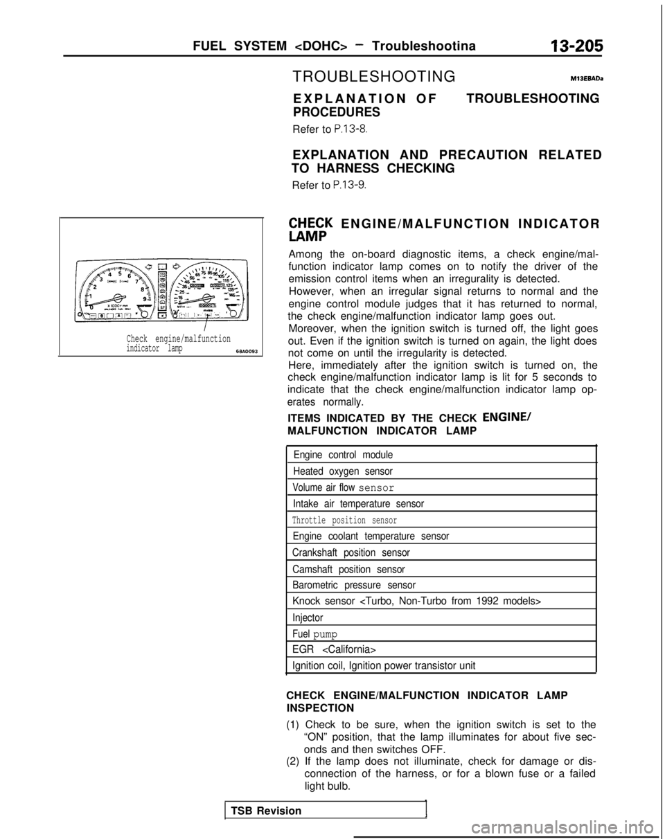
Check engine/malfunctionindicator lamp6w.0093
TROUBLESHOOTINGM13EBADa
EXPLANATION O
F
PROCEDURES
Refer to P.13-8.
TROUBLESHOOTING
EXPLANATION AND PRECAUTION RELATED
TO HARNESS CHECKING
Refer to
P.13-9.
ft&;K ENGINE/MALFUNCTION INDICATO
R
Among the on-board diagnostic items, a check engine/mal-
function indicator lamp comes on to notify the driver of the
emission control items when an irregurality is detected. However, when an irregular signal returns to normal and the
engine control module judges that it has returned to normal,
the check engine/malfunction indicator lamp goes out. Moreover, when the ignition switch is turned off, the light goes
out. Even if the ignition switch is turned on again, the light does
not come on until the irregularity is detected. Here, immediately after the ignition switch is turned on, the
check engine/malfunction indicator lamp is lit for 5 seconds to
indicate that the check engine/malfunction indicator lamp op-
erates normally.
ITEMS INDICATED BY THE CHECK ENGINE/
MALFUNCTION INDICATOR LAMP
Engine control module
Heated oxygen sensor
Volume air flow sensor
Intake air temperature sensor
Throttle position sensor
Engine coolant temperature sensor
Crankshaft position sensor
Camshaft position sensor
Barometric pressure sensor
Knock sensor
Injector
Fuel pump
EGR
Ignition coil, Ignition power transistor unit
CHECK ENGINE/MALFUNCTION INDICATOR LAMP INSPECTION
(1) Check to be sure, when the ignition switch is set to the “ON” position, that the lamp illuminates for about five sec-
onds and then switches OFF.
(2) If the lamp does not illuminate, check for damage or dis-
connection of the harness, or for a blown fuse or a failed
light bulb.
TSB Revision
Page 479 of 1273
AUTO-CRUISE CONTROL SYSTEM - Troubleshooting
13-337
Trouble symptom
Cannot decelerate by using the
SET switch
Probable cause
Check chart No.Remedy
Temporary damagedNo. 2Repair the harness or
or disconnected wir-
replace the SET
ing of SET switchswitch.
Actuator circuit poorNo. 5Repair the harness or
replace the actuator.
Malfunction of the
1 Malfunction of the
ECU
-Replace the ECU.
Cannot accelerate or resume
speed by using the RESUME
switch.
Damaged or discon- No. 3 netted
wiring, or
short-circuit, of
RE-
SUME switch input
circuit Repair the harness or
replace the RESUME
switch.
Actuator circuit poor No. 5iRepair the harness or
; contact replace the actuator.
Malfunction of the
actuator
,
Malfunction of the-Replace the ECU.
ECU
Jute-cruise control system can be i Malfunction of the No. 4
Repair the vehicle-
set while traveling at a vehiclevehicle-speed sensor speed sensor system,
speed of less than 40 km/h (25circuitor replace the part.
nph), or there is no automatic
zancellation at that speed.
Malfunction of the
speedometer cable or
the speedometer
drive gear
Malfunction of the
’ ECU
-Replace the ECU.
The indicator light of the combination Damaged or discon-
neter does not illuminate. netted bulb of
But auto-cruise control system isindicator light
lormal.1
-Repair the harness or
replace the light
bulb.
Harness damaged or
disconnected
TSB Revision
Page 495 of 1273
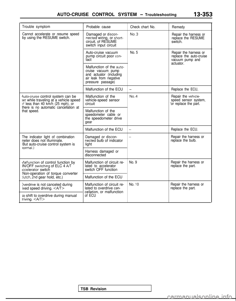
AUTO-CRUISE CONTROL SYSTEM - Troubleshooting13-353
Trouble symptom
Probable causeCheck chart No.Remedy
Cannot accelerate or resume speed
No.3
by using the RESUME switch. Damaged or discon- netted wiring, or short-
Repair the harness orcircuit, of RESUMEreplace the RESUMEswitch.
switch input circuit
Auto-cruise vacuum
No. 5Repair the harness orpump circuit poor con-replace the auto-cruisetactvacuum pump and
actuator.
Malfunction of the auto-cruise vacuum pump
and actuator (including
air leak from negative
pressure passage)
Malfunction of the ECU-Replace the ECU,
4uto-cruise control system can be Malfunction of theNo.4Repair the vehicle-set while traveling at a vehicle speed vehicle-speed sensorspeed sensor system,3f less than 40 km/h (25 mph), orcircuit‘or replace the part.
there is no automatic cancellation at
that speed.
Malfunction of thespeedometer cable orthe speedometer drivegear
The indicator light of combination
neter does not illuminate. But auto-cruise control system is
iormal.)
Malfunction of the ECU-Replace the ECU.
Damaged or discon--Repair the harness ornetted bulb of indicatorreplace the bulb.light
Harness damaged ordisconnected
vlalfunction of control function by Malfunction of circuit re-No. 9Repair the harness orIN/OFF switchrng of ELC 4 ATlated to accelerator
replace the part.accelerator switchswitch OFF function
Non-operation of torque converter
:lutch, 2nd gear hold, etc.) Malfunction of the ECU
Overdrive is not canceled during Malfunction of circuit re-No. 10Repair the harness or
ixed speed driving. lated to overdrive can-replace the part.cellation, or malfunction\lo shift to overdrive during manualIriving.
of ECU
TSB Revision
Page 1026 of 1273
ACTIVE-ELECTRONIC CONTROL SUSPENSIONService Adjustment- Procedures33B-87
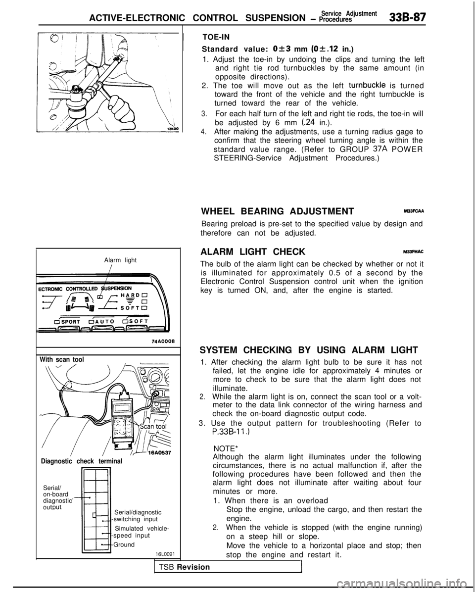
Alarm light
With scan tool
Diagnostic check terminal
Serial/
on-board
diagnostic’
outwt
TSB RevisionI
Serial/diagnostic
-switching input
Simulated vehicle-
-speed input
-Ground
16LOO91
!
TOE-IN
Standard value:
Ok3 mm (Of.12 in.)
1. Adjust the toe-in by undoing the clips and turning the left and right tie rod turnbuckles by the same amount (in
opposite directions).
2. The toe will move out as the left turnbuckle
is turned
toward the front of the vehicle and the right turnbuckle is
turned toward the rear of the vehicle.
3.For each half turn of the left and right tie rods, the toe-in will
be adjusted by 6 mm
(.24 in.).
4.After making the adjustments, use a turning radius gage to confirm that the steering wheel turning angle is within the
standard value range. (Refer to GROUP 37A
POWER
STEERING-Service Adjustment Procedures.)
WHEEL BEARING ADJUSTMENT
M33FcAA
Bearing preload is pre-set to the specified value by design and
therefore can not be adjusted.
ALARM LIGHT CHECK
MPFNAC
The bulb of the alarm light can be checked by whether or not it is illuminated for approximately 0.5 of a second by the
Electronic Control Suspension control unit when the ignition
key is turned ON, and, after the engine is started.
SYSTEM CHECKING BY USING ALARM LIGHT 1. After checking the alarm light bulb to be sure it has not failed, let the engine idle for approximately 4 minutes ormore to check to be sure that the alarm light does not
illuminate.
2.While the alarm light is on, connect the scan tool or a volt- meter to the data link connector of the wiring harness and
check the on-board diagnostic output code.
3. Use the output pattern for troubleshooting (Refer to
P.33B-11.)
NOTE*
Although the alarm light illuminates under the following
circumstances, there is no actual malfunction if, after the
following procedures have been followed and then the
alarm light does not illuminate after waiting about four
minutes or more.
1. When there is an overload Stop the engine, unload the cargo, and then restart the
engine.
2.When the vehicle is stopped (with the engine running)
on a steep hill or slope.Move the vehicle to a horizontal place and stop; then
stop the engine and restart it.
Page 1079 of 1273
338-140 ACTIVE-ELECTRONIC CONTROL SUSPENSION - t:%%%=mb’y’
INDICATOR ASSEMBLY
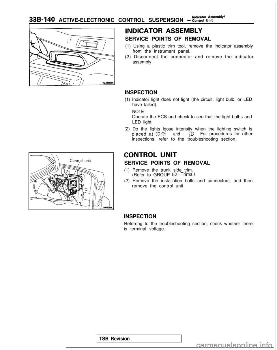
SERVICE POINTS OF REMOVAL(1) Using a plastic trim tool, remove the indicator assembly from the instrument panel.
(2) Disconnect the connector and remove the indicator assembly.
INSPECTION
(1) Indicator light does not light (the circuit, light bulb, or LED have failed).
NOTE
Operate the ECS and check to see that the light bulbs and
LED light.
(2) Do the lights loose intensity when the lighting switch is placed at
50 0:and$D . For procedures for other
inspections, refer to the troubleshooting section.
CONTROL UNIT
SERVICE POINTS OF REMOVAL
(1) Remove the trunk side trim. (Refer to GROUP
52-Trims.)
(2) Remove the installation bolts and connectors, and then
remove the control unit.
INSPECTION Referring to the troubleshooting section, check whether there
is terminal voltage.
TSB Revision
Page 1137 of 1273
35-16SERVICE BRAKES - Anti-lock Braking System Troubleshooting
TROUBLESHOOTING (ABS-FWD)
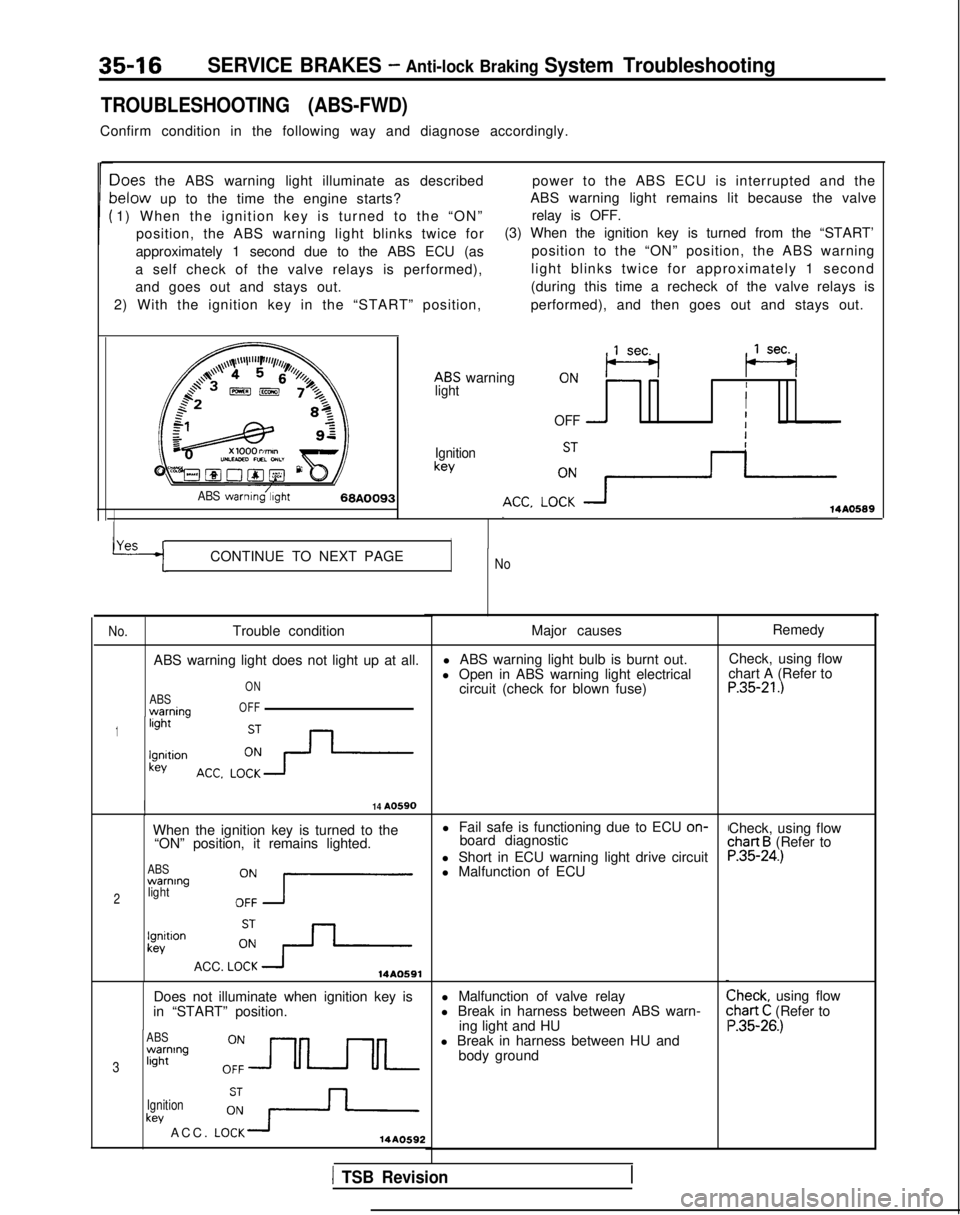
Confirm condition in the following way and diagnose accordingly.
Ioes the ABS warning light illuminate as describedpower to the ABS ECU is interrupted and the
lelow up to the time the engine starts?ABS warning light remains lit because the valve
1) When the ignition key is turned to the “ON” relay is OFF.
position, the ABS warning light blinks twice for (3) When the ignition key is turned from the “START’
approximately 1 second due to the ABS ECU (as position to the “ON” position, the ABS warning
a self check of the valve relays is performed), light blinks twice for approximately 1 second
and goes out and stays out. (during this time a recheck of the valve relays is
2) With the ignition key in the “START” position, performed), and then goes out and stays out.
ABS warning
,,lseq (se+
lightII
OFF -I
Ignitionkey
ABS warnmg/;,ght68A009314A0589
YAS rICONTINUE TO NEXT PAGENo
No.
Trouble condition
ABS warning light does not light up at all.
ABSwarnina
ON
OFF
1light -
lgnltionkey
I14 A0590
When the ignition key is turned to the l Fail safe is functioning due to ECU on-
“ON” position, it remains lighted. board diagnostic
ABSwarning
2lightOZ7
l Short in ECU warning light drive circuit
l Malfunction of ECU
lgnitlonkev
ACC. LOi+14A0591
Does not illuminate when ignition key is
in “START” position.
ABSwarning
3light
Ignition
key ACC. LO:+14AO592
Major causes
l ABS warning light bulb is burnt out.
l Open in ABS warning light electrical circuit (check for blown fuse)
l Malfunction of valve relay
l Break in harness between ABS warn- ing light and HU
l Break in harness between HU and body ground Remedy
Check, using flow
chart A (Refer to
P.35-21.)
Check, using flowchart B (Refer toP.35-24.)
Check, using flow:hart C (Refer to ‘.35-26.)
1 TSB Revision