1989 MITSUBISHI GALANT low oil pressure
[x] Cancel search: low oil pressurePage 7 of 1273
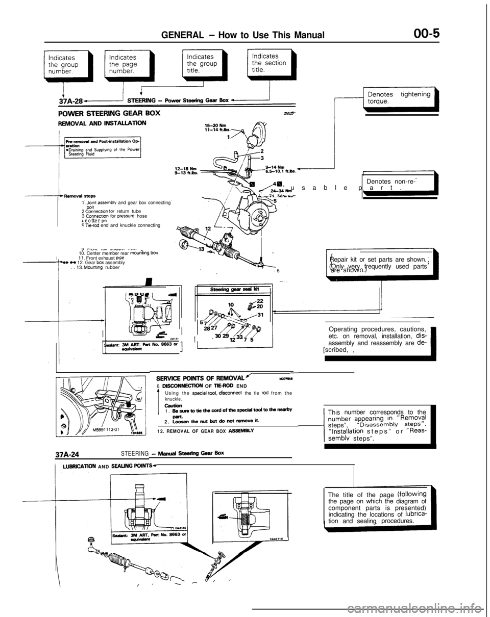
GENERAL - How to Use This Manual
QfitIIICQ CTEEQINC CFAR RnY..^-TV..&” Y.LLI.II.Y Y_.. w-1.
REMOVAL AND INSTALLATION
1, Jpn assemble and gear box connecting
2 Connectlo” for return tube
3 Connectm
for pressure hose4 cotter P!”6 T!e-rod end and knuckle connecting
I
J rl”.#l ~“,. dLlrr_. ..__
10. Center member rear mouniing
bou11, Front exhaust p’pe4. H 12. Gear box assembly
. . 13. Mounting rubber Denotes non-re-
p usable part
.
Y.T-*c As..
-
6
Repair kit or set parts are shown.
(Only very frequently used parts
Operating procedures, cautions,
II-’ iY,W11 ’etc. on removal, installation, dis-
se&an: 3rM&rr&paNo.~3W[scribed, ,~ 1assembly and reassembly are
de-
37A-24STEERING- NINA Steering Gear Box
-SERVICE POINTS OF
REMOVALJll37?kM6. DlSCONNECllON OF TIEROD END
Using the special tool, disconnect
the tie rod from theknuckle.ceurion1. BesretotiethewrdofthespeciaitodtomenP-.2. Loosenthenutbutdonotremoveit.
12. REMOVAL OF GEAR BOX ASSEMBLY
Thus number corresponds to the
number ?pyi:,“~&‘R~;;?Isteps”,“Installation steps” or “Reas-semblv steps”.
/LUBRlCATlON AND SEALING POINTS-
The title of the page (fOilOWingthe page on which the diagram of
component parts is presented)
indicating the locations of lubnca-
tion and sealingprocedures.
Page 32 of 1273
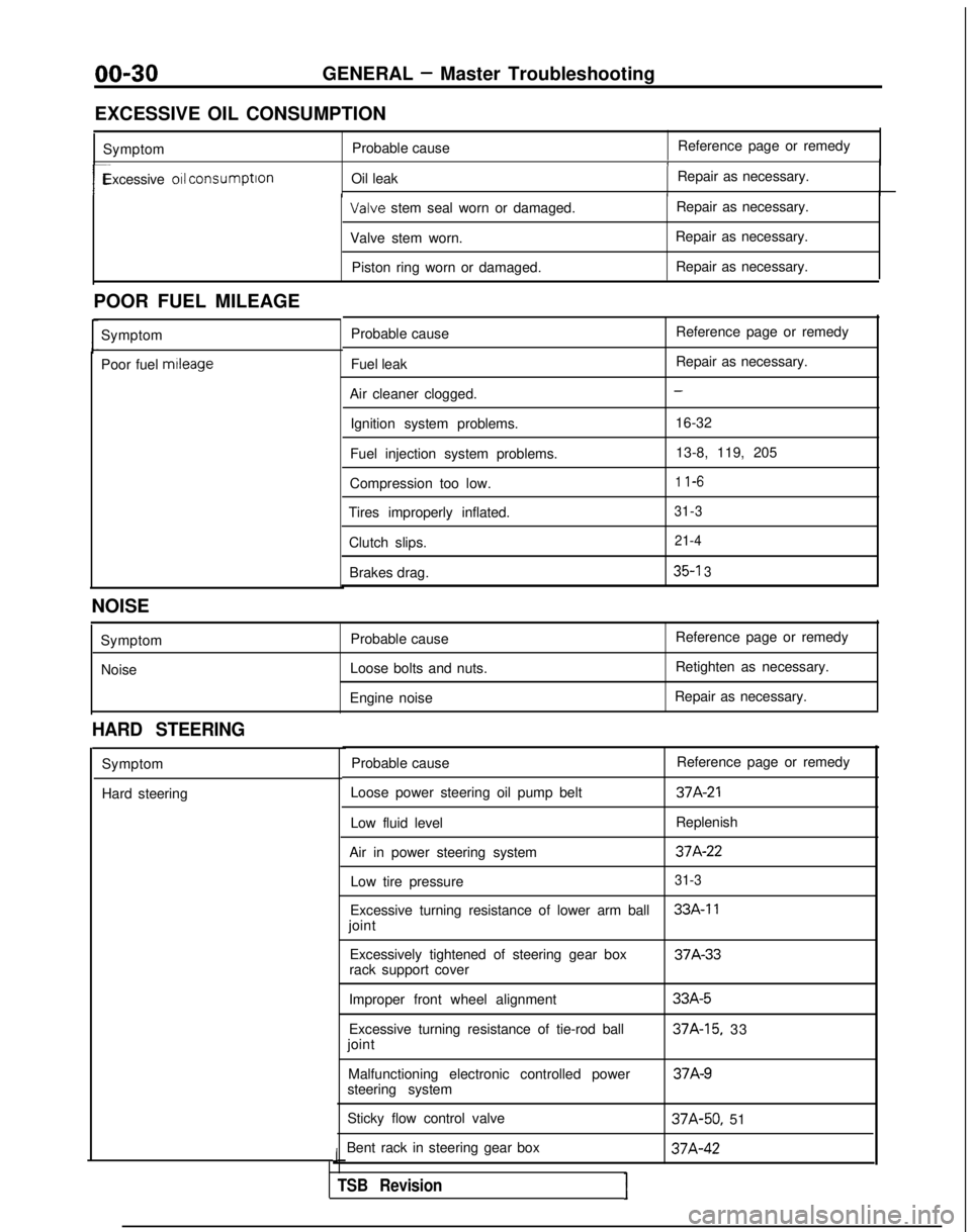
00-30GENERAL - Master Troubleshooting
EXCESSIVE OIL CONSUMPTION Symptom Probable cause Reference page or remedy
1
r-Excessive 011 consumption
Oil leak Repair as necessary.I Valve
stem seal worn or damaged. Repair as necessary.
Valve stem worn. Repair as necessary.
Piston ring worn or damaged. Repair as necessary.
POOR FUEL MILEAGE Symptom
Poor fuel mtleage
Probable cause
Fuel leak
Air cleaner clogged. Ignition system problems.
Fuel injection system problems.
Compression too low.
Tires improperly inflated.
Clutch slips.Brakes drag. Reference page or remedy
Repair as necessary.
-
16-32
13-8, 119, 205
1 l-6
31-3 21-4
35-l 3
NOISE
SymptomNoise Probable cause
Loose bolts and nuts.
Engine noise Reference page or remedy
Retighten as necessary.
Repair as necessary.
HARD STEERING
Symptom
Hard steering Probable cause
Reference page or remedy
Loose power steering oil pump belt
37A-21
Low fluid level Replenish
Air in power steering system
37A-22
Low tire pressure31-3
Excessive turning resistance of lower arm ball33A-11
joint Excessively tightened of steering gear box 37A-33
rack support cover
Improper front wheel alignment
Excessive turning resistance of tie-rod ball
joint
Malfunctioning electronic controlled power
steering system
Sticky flow control valve
Bent rack in steering gear box
J
TSB RevisionI
33A-5
37A-15, 33 37A-9
37A-50,
51 37A-42
Page 33 of 1273
GENERAL - Master Troubleshooting
00-31
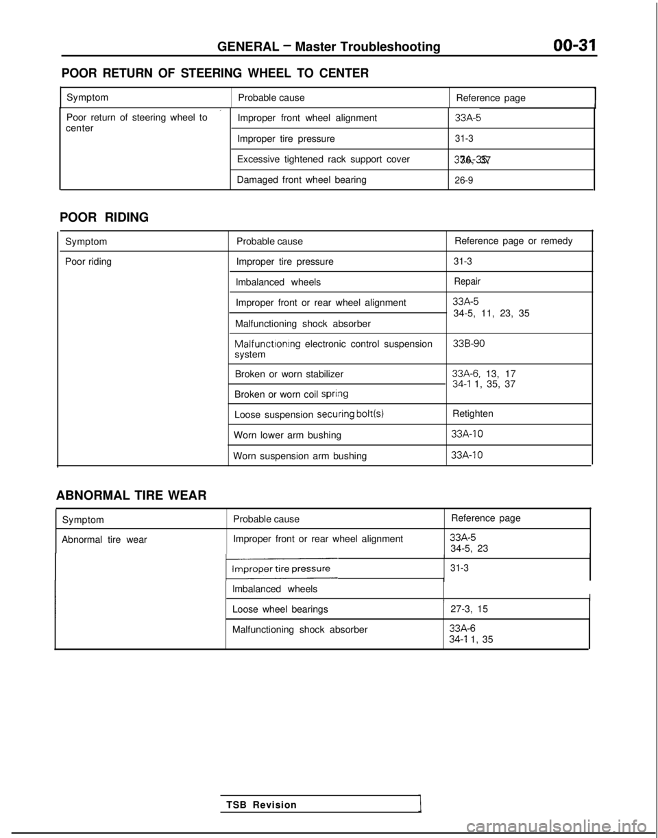
POOR RETURN OF STEERING WHEEL TO CENTER
Symptom
Probable cause Reference page
’Poor return of steering wheel to
Improper front wheel alignment33A-5center
Improper tire pressure31-3
Excessive tightened rack support cover 37A-35, 36, 37
Damaged front wheel bearing
26-9
POOR RIDING
Symptom
Poor riding Probable cause
Reference page or remedy
Improper tire pressure
31-3
lmbalanced wheelsRepair
Improper front or rear wheel alignment33A-5
34-5, 11, 23, 35
Malfunctioning shock absorber Malfunctioning
electronic control suspension
33B-90system
Broken or worn stabilizer
33A-6. 13, 1734-l 1, 35, 37
Broken or worn coil spri#ng
Loose suspension secuiring bolt(s)
Retighten
Worn lower arm bushing
33A-10
Worn suspension arm bushing 33A-IO
TSB Revision
ABNORMAL TIRE WEAR
Symptom
Abnormal tire wear Probable cause
Improper front or rear wheel alignment Reference page
33A-534-5, 23
131-3
lmbalanced wheelsII
Loose wheel bearings
27-3, 15
Malfunctioning shock absorber
33A-634-l 1, 35
Page 34 of 1273
00-32
GENERAL - Master Troubleshooting
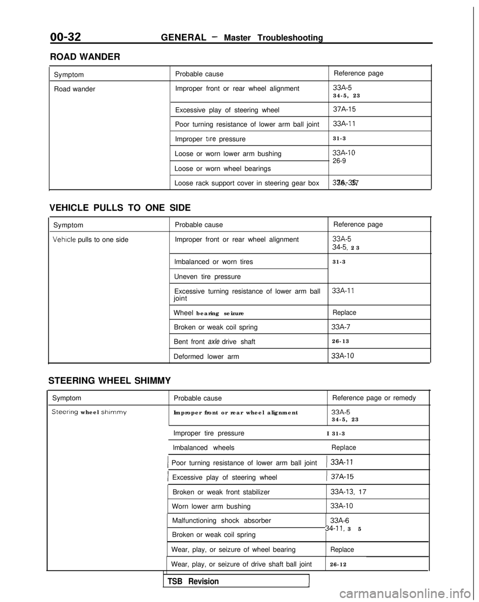
ROAD WANDER Symptom
Road wander Probable cause
Improper front or rear wheel alignment Reference page
33A-534-5, 23
Excessive play of steering wheel
37A-15
Poor turning resistance of lower arm ball joint33A-11
Improper tire pressure 31-3
Loose or worn lower arm bushing
33A-10
26-9
Loose or worn wheel bearings
Loose rack support cover in steering gear box 37A-35. 36, 37
VEHICLE PULLS TO ONE SIDE Symptom Probable cause Reference page
Vehrcle pulls to one side
Improper front or rear wheel alignment33A-5
34-5. 2
3
lmbalanced or worn tires 31-3
Uneven tire pressure Excessive turning resistance of lower arm ball
33A-17joint
Wheel bearing seizure
Replace
Broken or weak coil spring33A-7
Bent front axle drive shaft 26-13
Deformed lower arm
33A-10
STEERING WHEEL SHIMMY
Symptom
Steerlng wheel shlmmy
Probable cause
Improper front or rear wheel alignment Reference page or remedy
33A-534-5, 23
Improper tire pressure I 31-3
lmbalanced wheels
Replace
1 Poor turning resistance of lower arm ball joint) 33A-11
] Excessive play of steering wheel) 37A-15
Broken or weak front stabilizer
Worn lower arm bushing33A-13. 17
33A-10
Malfunctioning shock absorber
Broken or weak coil spring
Wear, play, or seizure of wheel bearing33A-6
34-11, 3
5
Replace
Wear, play, or seizure of drive shaft ball joint
26-12
TSB Revision1
Page 43 of 1273
GENERAL - Maintenance Service00-41
-1
6COOO9
L!6COO39
OlR0344
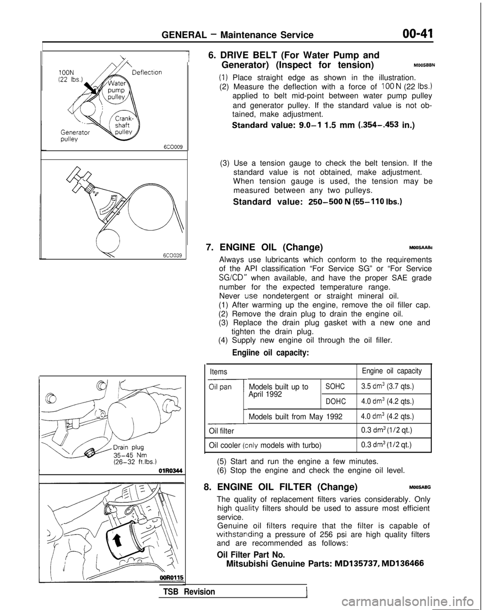
6. DRIVE BELT (For Water Pump and
Generator) (Inspect for tension)
MOOSBBN
(1) Place straight edge as shown in the illustration.
(2) Measure the deflection with a force of
100 N (22 Ibs.)
applied to belt mid-point between water pump pulley
and generator pulley. If the standard value is not ob-
tained, make adjustment.
Standard value: 9.0-l 1.5 mm (.354-.453
in.)
(3) Use a tension gauge to check the belt tension. If the standard value is not obtained, make adjustment.
When tension gauge is used, the tension may be
measured between any two pulleys.
Standard value:
250-500 N (55-110
Ibs.)
7. ENGINE OIL (Change)MOOSAABc
Always use lubricants which conform to the requirements
of the API classification “For Service SG” or “For Service SG/CD”
when available, and have the proper SAE grade
number for the expected temperature range.
Never
Lose nondetergent or straight mineral oil.
(1) After warming up the engine, remove the oil filler cap.
(2) Remove the drain plug to drain the engine oil. (3) Replace the drain plug gasket with a new one and
tighten the drain plug.
(4) Supply new engine oil through the oil filler.
Engiine oil capacity:
Items Engine oil capacity
Oil pan
1
Models built up toSOHC3.5 dm3 (3.7 qts.)
April 1992DOHC4.0 dm3 (4.2 qts.)
Models built from May 19924.0 dm3 (4.2 qts.)
Oil filter 0.3 dm3 (l/2 qt.)
Oil cooler
(clnly models with turbo) 0.3 dm3 (I/2 qt.)
(5) Start and run the engine a few minutes.
(6) Stop the engine and check the engine oil level.
8. ENGINE OIL FILTER (Change)
MOOSABG
The quality of replacement filters varies considerably. Only high
quatlity filters should be used to assure most efficient
service. Genuine oil filters require that the filter is capable of
withstarlding a pressure of 256 psi are high quality filters
and are recommended as follows:
Oil Filter Part No.
Mitsubishi Genuine Parts: MD135737,
MD136466
TSB Revision
Page 44 of 1273
00-42GENERAL -Maintenance Service
ENGINE OIL FILTER SELECTION
This vehicle is equipped with a full-flow, throw-away oilfilter.
The same type of replacement filter is recommended as a replacement filter for this vehicle. It is possible, particularily
in cold weather, that this vehicle may develop high oil
pressure for a short duration. You should be sure that any replacement filter used on this vehicle is a high-quality filter
and is capable of withstanding a pressure of 256 psi (manufacturer’s specifications) to avoid filter and engine
damage. The following is a high-quality filter and is strongly
recommended for use on this vehicle
: Mitsubishi Engine
Oil Filter Part No. MD1 35737 or MD1 36466.
Any replacement oil filter should be installed in accordance
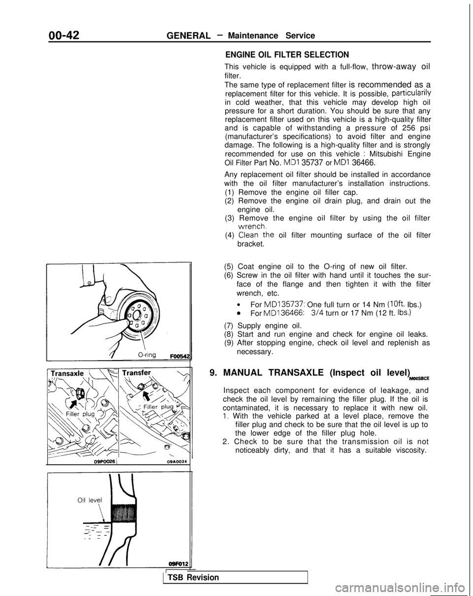
with the oil filter manufacturer’s installation instructions. (1) Remove the engine oil filler cap.
(2) Remove the engine oil drain plug, and drain out the
engine oil.
(3) Remove the engine oil filter by using the oil filter
(4)
GLr!he oil filter mounting surface of the oil filter
bracket.
OSPOO26 1 09A.0024(5) Coat engine oil to the O-ring of new oil filter.
(6) Screw in the oil filter with hand until it touches the sur-
face of the flange and then tighten it with the filter
wrench, etc.
l For MD135737:
One full turn or 14 Nm
(loft. Ibs.)0For MD136466:3/4 turn or 17 Nm (12 ft. Ibs.)
(7) Supply engine oil.
(8) Start and run engine and check for engine oil leaks.
(9) After stopping engine, check oil level and replenish as
necessary.
9. MANUAL TRANSAXLE (Inspect oil level)
MOO66CE
Inspect each component for evidence of leakage, and
check the oil level by remaining the filler plug. If the oil is
contaminated, it is necessary to replace it with new oil.
I. With the vehicle parked at a level place, remove the filler plug and check to be sure that the oil level is up to
the lower edge of the filler plug hole.
2. Check to be sure that the transmission oil is not noticeably dirty, and that it has a suitable viscosity.
TSB Revision
Page 45 of 1273
GENERAL - Maintenance Service00-43
1
O.AUTOMATIC
TRANSAXLE
Inspect fluid levelMOOSSDA
1. Drive until the fluid temperature reaches the usual ternperature
[70-80°C (160- 18O”F)I.
2. Plaice vehicle on level floor.
3.Move selector lever sequentially to every position to fill
torque converter and hydraulic circuit with fluid, then place lever in “N” Neutral position. This operation is
necessary to be sure that fluid level check is accurate.
4. Before removing dipstick, wipe all dirt from area around
dipstick. Then take out the dipstick and check the
condition of the fluid.
The transaxle should be overhauled under the following
conditions.l If there is a “burning” odor.
l If the fluid color has become noticeably blacker.
l If there is a noticeably great amount of metal particles in the fluid.
5.Chleck to see if fluid level is in “HOT” range on dipstick.
If fluid level is low, add ATF until level reaches “HOT”
range.
LO\N fluid level can cause a variety of conditions
because it allows pump to take in air along with fluid. Air
trapped in hydraulic circuit forms bubbles which make
fluid spongy. Therefore, pressures will be erratic. Improper filling can also raise fluid level too high. When
transaxle has too much fluid, gears churn up foam and cause same conditions which occur with low fluid level,
resulting in accelerated deterioration of ATF.In either case, air bubbles can cause overheating, fluid
oxidation, which can interfere with normal valve, clutch,
and servo operation. Foaming can also result in fluid escaping from transaxle vent where it may be mistaken
for a leak.
6. Be sure to examine fluid on dipstick closely. Chaqge
fluid
Drain
tlhe fluid and check whether there is any evidence of
contamination. Replenish with new fluid after the cause of any contamina-
tion
has been corrected.
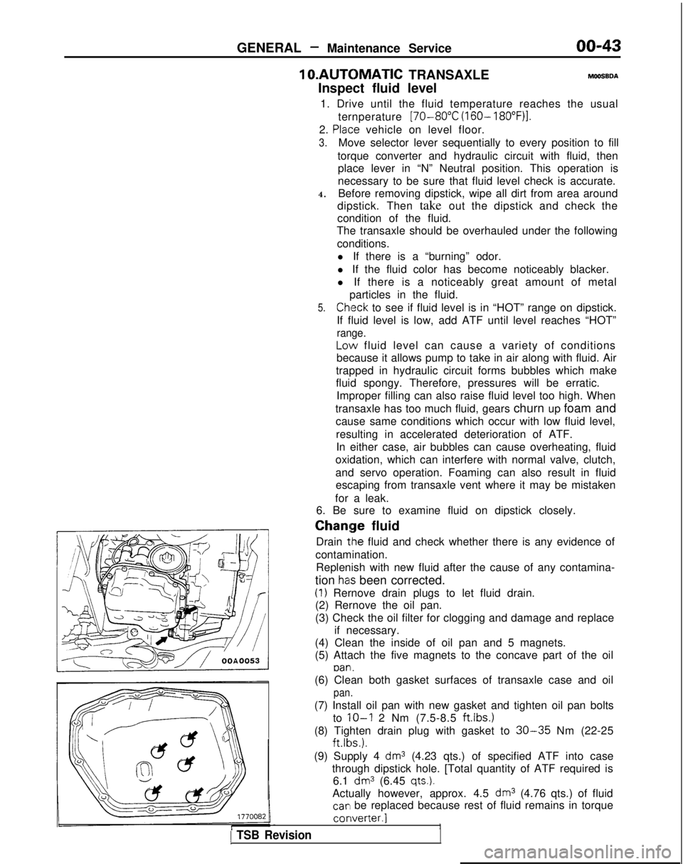
(1) Rernove drain plugs to let fluid drain.
(2) Rernove the oil pan.
(3) Check the oil filter for clogging and damage and replace
if necessary.
(4) Clean the inside of oil pan and 5 magnets.
(5) Attach the five magnets to the concave part of the oil
pan.
1 TSB Revision
(6) Clean both gasket surfaces of transaxle case and oil
pan.
(7) Install oil pan with new gasket and tighten oil pan bolts
to
IO-I 2 Nm (7.5-8.5 ftlbs.)
(8) Tighten drain plug with gasket to 30-35 Nm (22-25 ft.lbs.).
(9) Supply 4
dm3 (4.23 qts.) of specified ATF into case
through dipstick hole. [Total quantity of ATF required is 6.1
dm3 (6.45 qts.).
Actually however, approx. 4.5 dm3 (4.76 qts.) of fluid
car1 be replaced because rest of fluid remains in torque converter.]
1
Page 51 of 1273
11-I
CONTENTSM11AA-
ENGINE
........................
53
CAMSHAFT AND CAMSHAFT OIL
SEALS..........................................68
CYLINDER HEAD GASKET
.................73
ENGINE ASSEMBLY
.........................63
OIL PAN AND OIL SCREEN ...............71
SERVICE ADJUSTMENT
PROCEDURES................................
57
Basic
Idle Speed Adjustment
...........................
.
Refer to GROUP 13
Compression Pressure Check ..............
59
Curb- Idle Speed Adjustment_.___..__._____....___._....Refer to GROUP 13
Dash Pot Inspection and Adjustment 58
Drive Belts Tension Adjustment . 6
1
Engine Oil Check . . .
_. _. . . _. . . . . . . 57
Ignition Timing Adjustment
__..._.__...................Refer to GROUP 16
Lash Adjusters Check ......................
.
57
Manifold Vacuum Inspection
..............
.
60
SPECIAL TOOLS.............................56
SPECIFICATIONS
............................53
General Specifications .....................
.
53
Sealants and Adhesives ....................
56
Service Specifications......................
.
53
Torque Specifications
......................
.
54
TIMINGBELT.................................80
TROUBLESHOOTING
........................56
E,NGINE
CAMSHAFT AND CAMSHAFT OIL
SEAL. . . . . . . . . . . . . . . . . . . ..*............ . . . . . . . . . .19
CYLINDER HEAD GASKET..................25
ENGINE ASSEMBLY.........................14
OIL PAN AND OIL SCREEN. . . . . . . . . . . . . . . .23
SERVICE ADJUSTMENT
PROCEDURES. . . . . . . . . . . . . . . . . . . . . . . ..*.......7
Basic Idle Speed Adjustment
. . . . . . . .._......... . Refer to GROUP 13
Compression Pressure Check . .
.
8
Curb Idle Speed Adjustment
.__................ _. . . . Refer to GROUP 13
Drive Belts Tension Adjustment .........
.
12
Engine Oil Check
..........................
.
7
Ignition Timing Adjustment
_...___............... . . . . . Refer to GROUP 16
Lash Adjusters Check . . . . . . . . . . . .
7
Manifold Vacuum Inspection . . . . . . . . . .9
Timing Belt Tension Adjustment . . . .10
SPECIAL TOOLS . . . . . . . . . . . . . . . . . . . . . . . . . . . . . \
.5
SPECIFICATIONS. . . . . . . . . . . . . . . . . . . . . . . . . . . . .2
General Specifications _. _.2
Sealants and Adhesives
._ _. . . . . . . .5
Service Specifications . . . .2
Torque Specifications . . . . . . . . . . . . . . . .4
TIMING BELT. . . . . . . . . . . . . . . . . . . . . . . . . . . . . . . . .34
TROUBLESHOOTING. . . . . . . . . . . . . . . . . . . . m.. .6
Compression Too Low
Connecting Rod Noise/Main Bearing Noise Excessive Engine Rolling and Vibration
Noisy Valves
Oil Pressure Drop
Oil Pressure Too High
Timing Belt Noise