1989 MITSUBISHI GALANT low oil pressure
[x] Cancel search: low oil pressurePage 224 of 1273
13-82 FUEL SYSTEM
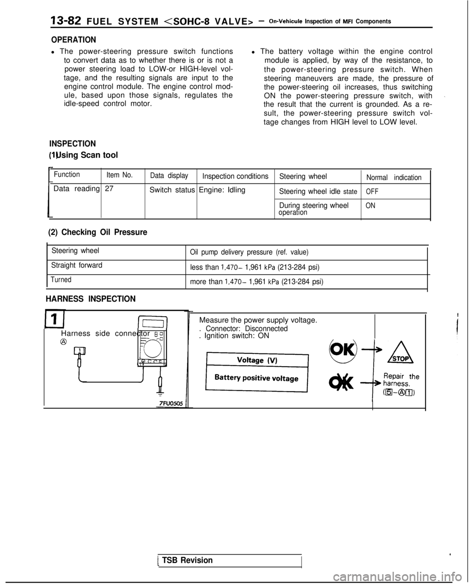
OPERATION
l The power-steering pressure switch functions
to convert data as to whether there is or is not apower steering load to LOW-or HIGH-level vol-
tage, and the resulting signals are input to the engine control module. The engine control mod-
ule, based upon those signals, regulates the
idle-speed control motor. l The battery voltage within the engine control
module is applied, by way of the resistance, to
the power-steering pressure switch. When
steering maneuvers are made, the pressure of
the power-steering oil increases, thus switching
ON the power-steering pressure switch, with
the result that the current is grounded. As a re-
sult, the power-steering pressure switch vol-
tage changes from HIGH level to LOW level.
INSPECTION I) Using Scan tool
Function
Item No.
Data reading 27
Data displayInspection conditions Steering wheelNormal indication
Switch status Engine: IdlingSteering wheel idle stateOFF
During steering wheelONoperation
(2) Checking Oil Pressure
Steering wheel
Straight forward
Turned
Oil pump delivery pressure (ref. value)
less than 1,470- 1,961 kPa (213-284 psi)
more than
1,470- 1,961 kPa (213-284 psi)
HARNESS INSPECTION
I-E-I
Harness side connector 6 0
@=- -0
Q
4 1
Measure the power supply voltage.
. Connector: Disconnected. Ignition switch: ON
[ TSB Revision
Page 232 of 1273
13-90 FUEL SYSTEM
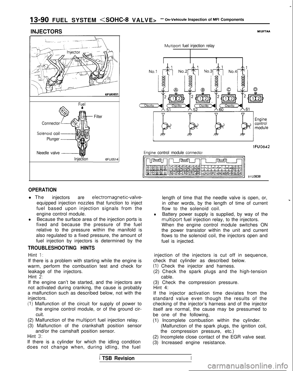
INJECTORS
Fuel
Connector
Solenoid coil
Plunger
Needle valve -----I
InjectionFilter6FUO514
M13rrAA
Multiport
fuel injection relay
No.1 &j No.2& No.3& No,4+
tI
lFUO642
Engine control module connector
CJ=JW=U-I
0 1 LO636
OPERATION
l The
injectorsare electromagnetic-valve-
equipped injection nozzles that function to inject
fuel based upon injection signals from the
engine control module.
lBecause the surface area of the injection ports is
fixed and because the pressure of the fuel
relative to the pressure within the manifold is
also regulated to a fixed pressure, the amount of
fuel injection by injectors is determined by the
TROUBLESHOOTING HINTS
Hint 1:
If there is a problem with starting while the engine is
warm, perform the combustion test and check for leakage of the injectors.
Hint
2,
If the engine can’t be started, and the injectors are
not activated during cranking, the cause is probably
a malfunction such as described below, not with the
injectors.
(I) Malfunction of the circuit for supply of power to the engine control module, or of the ground cir-
cuit.
(2) Malfunction of the multiport fuel injection relay.
(3) Malfunction of the crankshaft position sensor and/or the camshaft position sensor.
Hint
3.
If there is a cylinder for which the idling condition
does not change when, during idling, the fuel length of time that the needle valve is open, or,
in other words, by the length of time of current
~-
flow to the solenoid coil.
lBattery power supply is supplied, by way of the
multiport fuel injection relay, to the injectors.
When the engine control module switches ON
the power transistor within the unit and current
flows to the solenoid coil, the injectors open and
fuel is injected.
injection of the injectors is cut off in sequence,
check that cylinder as described below.
(1) Check the injector and harness.
(2) Check the spark plugs and the high-tension
cable.
(3) Check the compression pressure. Hint 4:
If the injector activation time deviates from the
standard value even though the results of the
checking of the injector’s harness and of the injector itself are normal, the cause may be pressumed to
be one of the following,
(1) Incomplete combustion within the cylinder. (Malfunction of the spark plugs, the ignition coil,
the compression pressure, etc.)
(2) Incomplete close contact of the EGR valve seat.
(3) Increased engine resistance.
1 TSB RevisionI
Page 243 of 1273
FUEL SYSTEM
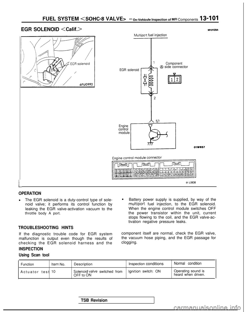
EGR SOLENOID
L
Multiport fuel injection
EGR solenoid Component@I side connector
_ ”
Enginecontrol
module
LOlW557
01 LO838
OPERATION
l The EGR solenoid is a duty-control type of sole-
noid valve; it performs its control function by
leaking the EGR valve-activation vacuum to the
throttle body A port.
TROUBLESHOOTING HINTS
If the diagnostic trouble code for EGR system
malfunction is output even though the results of
checking the EGR solenoid harness and the
INSPECTION
l Battery power supply is supplied, by way of the
multiport fuel injection, to the EGR solenoid.
When the engine control module switches OFF
the power transistor within the unit, current stops flowing to the coil, and the EGR valve-ac-
tivation negative pressure leaks.
component itself are normal, check the EGR valve,
the vacuum hose piping, and the EGR passage for
clogging.
Using Scan tool
Function Item
No.
Actuator test
10
Description Inspection conditionsNormal condition
$i;;,oi$;;alve switched from Ignition
switch: ON Operating sound is
heard when driven.
TSB Revision
Page 269 of 1273
FUEL SYSTEM
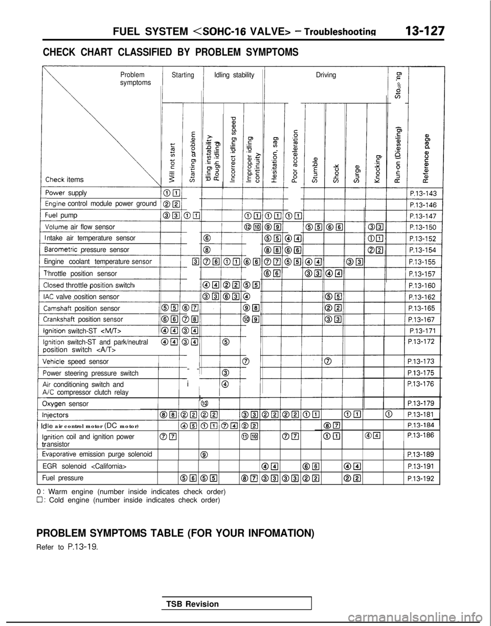
CHECK CHART CLASSIFIED BY PROBLEM SYMPTOMS
ProblemsymptomsStartingIdling stability Drivingr”
.-
%scn
E5
$4.a,o_
5;i
cz
iP.13-143
-
Ea,Ll2a
F.- s
G-
DE-
c-
Elc
-
-
>El
)El-
)I3-
)@I
I-
-
i
-
5‘32a,$%ba”
D&l DEI
i>El
-0%,a>+y -2.gPE.-50 z.E r2?p9 6=& g-
-
-Sheck items
‘ower
supply
%ginecontrol module power groundI
1 P.13-146
:uel pump
Jolume air flow sensor
B
f
E3
DELI @El
cP.13-162
P.13-165III P.13-167I
1/ P.l3-171 1
P.l3-172
P.l3-173
P.l3-175
P.13-176
P.l3-179
ntake air temperature sensor
BIB
DEI
0
DEl
3El
3
-I
iarometric
pressure sensor
ingine coolant temperature
sensor
‘hrottle position sensor
Iosed throttlepositionswitch
K valve oosition sensor
lamshaft position sensor
i-:rankshaft positionsensorIIlnition
switch-ST
-I---0lnition switch-ST and park/neutralosition switch
chicle
speed sensor
ower steering pressure switch
ir conditioning switch and/C compressor clutch relayI/I- IIlxygen sensor
@El@ P.l3-181
@ElP.13-184
@[email protected]
Ile air control motor (DC motor)
inition coil and ignition powerOFI@piJOEIansistor
tiaporative emission purge solenoid01 P.13-189
1 Id
kl
c
tr
t
EGR solenoid
Fuel pressureOIlI @El8E.l @El @El @[email protected]
0 : Warm engine (number inside indicates check order)
0 : Cold engine (number inside indicates check order)
PROBLEM SYMPTOMS TABLE (FOR YOUR INFOMATION)
Refer to P.13-19.
TSB Revision
Page 281 of 1273
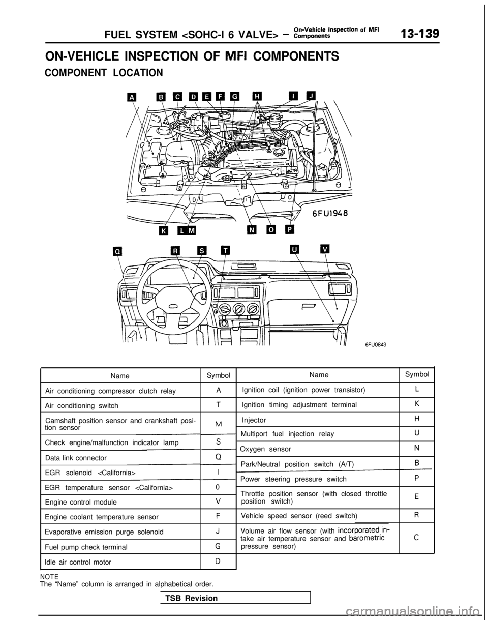
FUEL SYSTEM
ON-VEHICLE INSPECTION OF MFI COMPONENTS
COMPONENT LOCATION
6FUO843
Name Symbol NameSymbol
Air conditioning compressor clutch relay A
Ignition coil (ignition power transistor)
L
Air conditioning switchTIgnition timing adjustment terminalK
Camshaft position sensor and crankshaft posi- InjectorHMtion sensor- Multiport fuel injection relayU
Check engine/malfunction indicator lampS- Oxygen sensorN
Data link connectorQ- Park/Neutral position switch (A/T)6
EGR solenoid
EGR temperature sensor
Throttle position sensor (with closed throttle
position switch)
EEngine control modulev
Engine coolant temperature sensorFVehicle speed sensor (reed switch)R
Evaporative emission purge solenoidJVolume air flow sensor (with incorporated,in-
take air temperature sensor and barometncC
Fuel pump check terminalGpressure sensor)
Idle air control motor
D
NOTEThe “Name” column is arranged in alphabetical order. TSB Revision
Page 326 of 1273
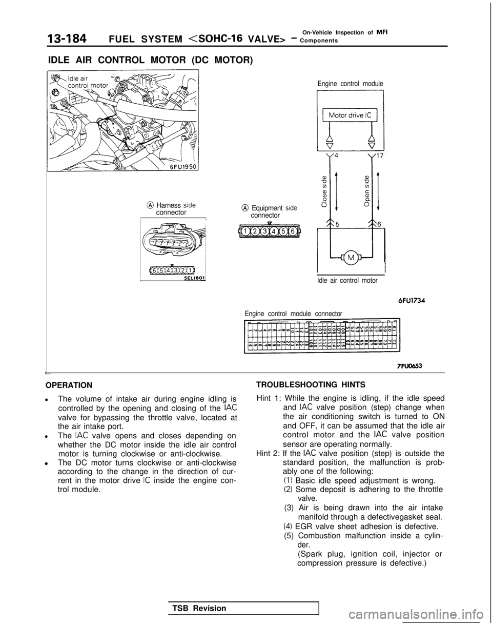
13-184
On-Vehicle Inspection of MFI
FUEL SYSTEM (SOHC-16 VALVE> - Components
IDLE AIR CONTROL MOTOR (DC MOTOR)
@ Harness sideconnectorI L
[@Ex@ziJ 1
5ELWOlJ
j
e;
j 55ww3 )A’,’/
@ Equipment sideconnector
Engine control module
Idle air control motor
6FU1734
Engine control module connector
7FUCJG3
OPERATION
lThe volume of intake air during engine idling is controlled by the opening and closing of the
IAC
valve for bypassing the throttle valve, located at
the air intake port.
lThe IAC valve opens and closes depending on
whether the DC motor inside the idle air control motor is turning clockwise or anti-clockwise.
l The DC motor turns clockwise or anti-clockwise
according to the change in the direction of cur-
rent in the motor drive
IC inside the engine con-
trol module. TROUBLESHOOTING HINTS
Hint 1: While the engine is idling, if the idle speed and
IAC valve position (step) change when
the air conditioning switch is turned to ON
and OFF, it can be assumed that the idle air
control motor and the
IAC valve position
sensor are operating normally.
Hint 2: If the
IAC valve position (step) is outside the
standard position, the malfunction is prob-
ably one of the following: (I)
Basic idle speed adjustment is wrong.
(2) Some deposit is adhering to the throttle
valve.
(3) Air is being drawn into the air intake
manifold through a defectivegasket seal.
(4) EGR valve sheet adhesion is defective.
(5) Combustion malfunction inside a cylin-
der.
(Spark plug, ignition coil, injector or
compression pressure is defective.)
TSB Revision
Page 338 of 1273
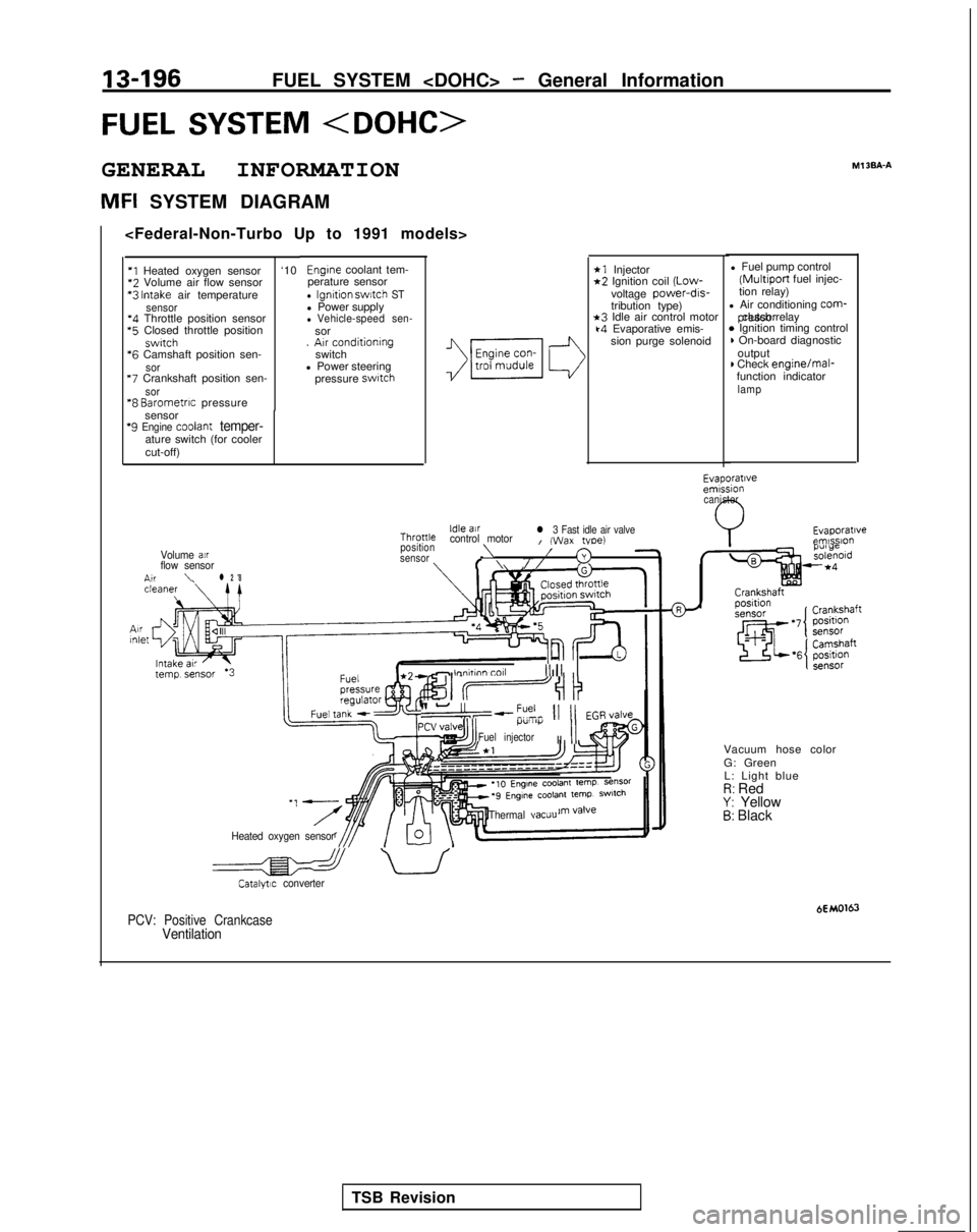
13-196FUEL SYSTEM
FUEL SYSTEM
GENERAL INFORMATION
MFI SYSTEM DIAGRAMMl
3BA-A
*1 Injector*2 Ignition coil
(Low-
voltage power-drs-
tribution type)
*3 Idle air control motork4 Evaporative emis-
sion purge solenoid l Fuel pump control (Multiport
fuel injec-
tion relay)
l Air conditioning
corm- pressor clutch relay
* Ignition timing control) On-board diagnostic
output
) Check engine/mal-
function indicator
lamp
Engine coolant tem-
perature sensor
l Ignition swatch STl Power supplyl Vehicle-speed sen-sor
. Arr conditioning
switch
l Power steering
pressure
swatch
‘I Heated oxygen sensor ‘10*2
Volume air flow sensor *3
Intake air temperaturesensor‘4 Throttle position sensor *5
Closed throttle position
swrtch *6
Camshaft position sen-
sor “7
Crankshaft position sen-
sor“8 Barometrrc pressure
sensor
‘9 Engine coolant temper-ature switch (for cooler
cut-off)
Evaporatrveemrssion canister
Evaporatrveemlsslo”Idle airThronlecontrol motorl 3 Fast idle air valveI (Wax tvoe)position\Volume air/sensor3flow sensorf \//n,r\l 2 '8
- lnnhnn toll III1 II
II-“,--?% 11 11 EGR,/alveI.l”lll)i
Fuel injectorII
II
Vacuum hose color
G: Green
L: Light blue
I?: RedY: Yellow5: Black
Heated oxygen sensor Thermal
vacuu
a uCatalytrc converter
HMO163PCV: Positive CrankcaseVentilation
TSB Revision
Page 339 of 1273
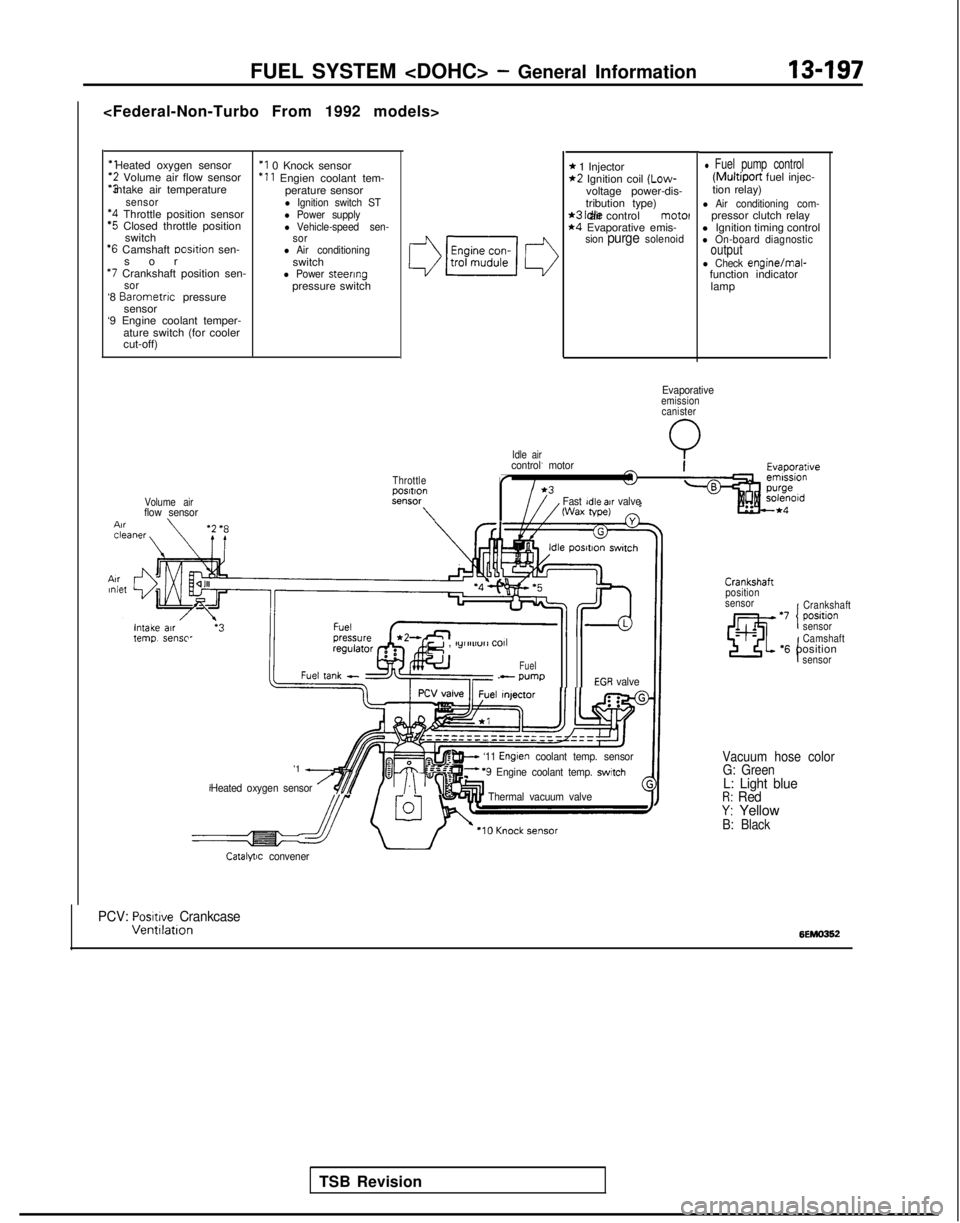
‘1 Heated oxygen sensor‘2 Volume air flow sensor
“3 intake air temperature
sensor‘4 Throttle position sensor‘5 Closed throttle position
switch
‘6 Camshaft Dosltion sen-
so
r
*7 Crankshaft position sen-sor‘8
Barometnc
pressure
sensor
‘9 Engine coolant temper-
ature switch (for cooler
cut-off)
‘I 0 Knock sensor ‘11
Engien coolant tem-
perature sensor
l Ignition switch STl Power supplyl Vehicle-speed sen-
sor
l Air conditioningswitchl Power steeringpressure switch
Volume airflow sensor \
Idle air
FUEL SYSTEM
* 1 Injector*2 Ignition coil (Low-
voltage power-dis-
tribution type)
*3 Idle air control motel*4 Evaporative emis-sion purge solenoid
l Fuel pump control (Multiport
fuel injec-
tion relay)
l Air conditioning com-pressor clutch relay
l Ignition timing control
l On-board diagnosticoutputl Check engine/mal-
function indicator
lamp
Evaporativeemissioncanister
Q
ThrottlepOSltlOnSt?“SW
\
control motor
r
Fast Idle air valveWax tape)
TSB Revision
e , lylllll”rl
COll
Fuel- wmpEGR valve
'1 A
Heated oxygen sensor /$$y/.\‘“I
w ‘11 Englen coolant temp. sensorF ‘9 Engine coolant temp. switch
Thermal vacuum valve
Crankshaft
position
sensor
‘7 positlon ICrankshaft
sensor
I
Camshaft‘6 positionsensor
Vacuum hose color G: Green
L: Light blueR: RedY: YellowB: Black
Catalytic convener
PCV: Posmve CrankcaseVentllatlon6EMO362