1989 MITSUBISHI GALANT low oil pressure
[x] Cancel search: low oil pressurePage 759 of 1273
AUTOMATIC TRANSAXLE - Troubleshooting23-53
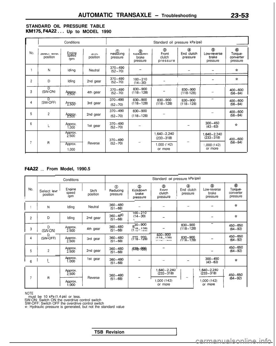
STANDARD OIL PRESSURE TABLE
KM175,
F4A22
. . .
Up to MODEL 1990
ConditionsStandard oil pressure kPa (psi)
N
O.1p -,-,..,-,,-_1Engine1Ch;J+1-0.1,,._,?...-1F%tclutch1E;;;;;;h1Lov$rse1To;;er13eleLL IfsYCIpositionspeedrpm
cl,1111positionneaucrng
pressurehlCI(aOWrIbrake
pressurepressure )Ipressure pressure
1NldlrngNeutral--*
2DIdling2nd gear 100-210
(14-30)
-
3(SWDON,Approx.830-900 830-900
400-600
--2,5004th gear
(118-128)
(118-128) (56-84)
(SWZFFI
Approx.3rd gear370-490830-900830-900 830-900
400-600-42.500
(52-70) (118-128)
(118-128)
(118-128)
(56-84)
52Approx.
2,5002nd gear370-490830-900 400-600-
(52-70) (118-128)
- (56-84)
-*6LApprox.1st gear370-4901,000
(52-70)-;g:gp
7R
A;pp56od(.
Approx.
1,000
Reverse370-490
(52-70) 1.640-2.240
1.640-2.240
(233-318)(233-318)--1.000 (142)1.OOO (I 42)or more
or moreF4A22
. . .From Model, 1990.5
ConditionsStandard 011 pressure kPa (Psi)
[email protected]“__l__^:__KrlrA,vrrnFrontEnd clutch
Low-reverseTorque-Select leve
brakeconverter
position pressure
‘ressurep-“cxm”1~ ,pressure
pressure
:rspeedcl,,,i;ne”“l;lily wmposition
pressureII
I I360-4801NIdlingNeutral(51~6P’2,--*--
TSB Revision
171 DIdling2nd gear360-4f (51-6b,
, \I
30?y;I;;p-*->i
30-900830-900450-650-1n-17RI- (118-128)(64-92)A2pPg4th gear360-480I I,.lY”-“Iv,(51-681
830-9004(SWZFF)A2pWg.3rdgear
(118-128)
,- .~,,,,“~.--,~.-lL”l,E%830-900-fllR-l='4g::;p
I I52
II
A2pg;.2nd gear~~~~~~p830-900-(118-128)-$g:;p
300-450
-*--”LApP&y.1stgear
(43-63)
1
ICI I
1 EEi2840 / _ 1 ‘~o~$~ ) 4iiIi;p7RReverse360-480
(51-68)
-1.000 (142)or more
NOTEmust be 10 kPa (I .4 psi) or less.
SW-ON: Switch ON the overdrive control switch SW-OFF: Switch OFF the overdrive control switch
*: Hydraulic pressure is generated, but not the standard value
Page 760 of 1273
23-54AUTOMATIC TRANSAXLE - Troubleshooting
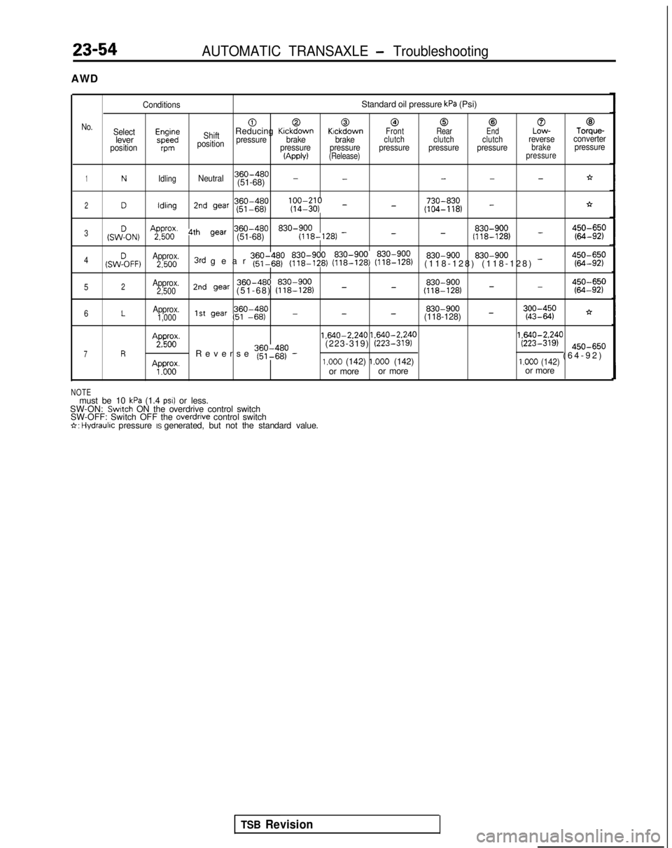
AWD
ConditionsStandard oil pressure kPa (Psi)
000@0@0@
No.Selectm;;ShiftReducing KickdownKickdownFront RearEndLow-Torque-leverpressurebrake brakeclutch clutch clutchreverseconverter
positionvmposition pressure pressure pressure pressure pressurebrakepressure(Apply)(Release)
pressure
1NIdlingNeutral360-480---*(51-68) --
360-480 lfyfI;;; _ 730-8302Dldlrng2nd war (51-68)
(104-118) -*-
(sw!oN)
AgFil’ 4th gear360-480 830-900 830-900
_3--(51-68)
(118-128)
-(118-128)g:gp 830-900
4(SW%FF)Approx. 830-9002.5003rd gear ~~~I$p (y$$zr (~$$EJ (??i??$)(118-128) (118-128) -g::;p
Approx.2nd gear 360-480 830-900
830-900450-650-52(51-68)
(118-128) _-2,500
(118-128) - (64-92)
6LApprox.360-480
830-9001,0001st gear (51 -66)---(118-128) -;:;I$;*
Ap&;.
1.640-2.240
1.640-2.240 1.640-2.240
7R ’Reverse ~~~$~p -(223-319)
(223-319)(223-319) @O-65,,
(64-92
)
Ap”do”o”.1.000 (142) 1.000 (142)1.000 (142)or more
or more or more
NOTEmust be 10 kPa (1.4 PSI) or less.
SW-ON: Switch ON the overdrive control switch
SW-OFF: Switch OFF the overdrrve control switch6: Hydraulrc pressure IS generated, but not the standard value.
TSB Revision
Page 761 of 1273
AUTOMATIC TRANSAXLE - Troubleshooting23-55
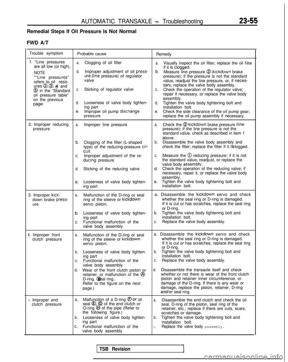
Remedial Steps If Oil Pressure Is Not Normal
FWD A/T Trouble symptom Probable cause Remedy
1. *Line pressuresa.
a.are all low (or high).Clogging of oil filter
Visually inspect the oil filter; replace the oil filte
NOTEb.Improper adjustment of oil press-
if it is cl,ogged.b.Measure line pressure @ (kickdown
brake
*“Line pressures” ure,(line
pressure) of regulator
pressure); if the pressure is not the standard
refers to oil ress-
valve
value, readjust the line pressure, or, if neces-
ures@,@, 4 and
6sary, replace the valve body assembly. @
in the “Standardc.Sticking of regulator valvec.Check the operation of the regulator valve;
oil pressure table” repair if necessary, or replace the valve body
on the previous assembly.
wed.Looseness of valve body tighten-d.Tighten the valve body tightening bolt and
ing part installation bolt.
e.Improper oil pump dischangee.Check the side clearance of the oil pump gear;
pressure replace the oil pump assembly if necessary.
2. Improper reducing
a.Improper line pressurea.Check the @ kickdown
brake pressure /line
pressure pressure); if the line pressure is not the
standard value, check as described in item 1
above.
b.Clogging of the filter (L-shapedb.Disassemble the valve body assembly and
type) of the reducing-pressure cir-
check the filter; replace the filter if it is clogged.
cuitc.Improper adjustment of the re-c.Measure the @ reducing pressure; if it is not
ducing
pressure the standard value, readjust, or replace the
valve body assembly.
d.Sticking of the reducing valved.Check the operation of the reducing valve; if
necessary, repair it, or replace the valve body
assembly.
e.Looseness of valve body tighten-e.Tighten the valve body tightening bolt and
ing part installation bolt.
3. Improper
kick-a.Malfunction of the D-ring or seal a. Disassemble the kickdown
servo and check
down brake press-
ring of the sleeve or kickdown
whether the seal ring or D-ring is damaged.
ure servo piston. If it is cut or has scratches, replace the seal ring
or D-ring.
b.Looseness of valve body tighten-b.Tighten the valve body tightening bolt and
ing part installation bolt.
c.Functional malfunction of thec.Replace the valve body assembly.
valve body assembly
1. Improper front clutch pressurea.Malfunction of the D-ring or seal a. Disassemble the kickdown
servo and check
ring of the sleeve or kickdown
whether the seal ring or D-ring is damaged.
servo piston. If it is cut or has scratches, replace the seal ring
or D-ring.
b.Looseness of valve body tighten-b.Tighten the valve body tightening bolt and
ing part installation bolt.
c.Functional malfunction of thec.Replace the valve body assembly.
valve body assembly
d.Wear of the front clutch piston ord.Disassemble the transaxle itself and check
retainer, or malfunction of the @
whether or not there is wear of the front clutch
D-ring. @ seal ring.
piston and retainer inner circumference, or
Refer to the figure on the next damage of the D-ring. If there is any wear or
page.) damage, replace the piston, retainer, D-ring and/or
seal ring.
i. Improper end
clutch pressurea.Malfunction of a D-ring @or oila.Disassemble the end clutch and check the oil
seal 0.0 of the end clutch or
O-ring 8 of the pipe (Refer to seal, D-ring of the piston, seal ring of the
the following figure.) retainer, etc.; replace if there are cuts, scars,
scratches or damage.
b.Looseness of valve body tighten-b.Tighten the valve body tightening bolt and
ing part installation bolt.
c.Functional malfunction of thec.Replace the valve body assembly.valve body assembly
TSB Revision
Page 762 of 1273
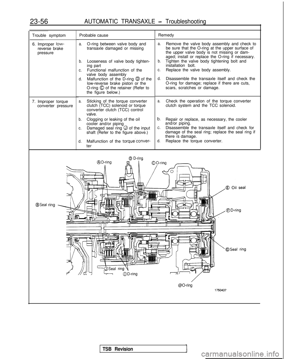
23-56AUTOMATIC TRANSAXLE - Troubleshooting
Trouble symptom
6. Improper low-
reverse brake
pressure Probable cause
a.O-ring between valve body and
transaxle damaged or missing
b.Looseness of valve body tighten-
ing part
c.Functional malfunction of the
valve body assembly
d.Malfunction of the D-ring 0 of the
low-reverse brake piston or the
O-ring
0 of the retainer (Refer to
the figure below.)
a.Sticking of the torque converter
clutch (TCC) solenoid or torque
converter clutch (TCC) control
valve.
b.Clogging or leaking of the oil
cooler and/or piping
c.Damaged seal ring Q of the input
shaft (Refer to the figure above.)
d.Malfunction of the torque’conver-
ter
7. Improper torque
converter pressure
0 D-ring
Remedy
a.Remove the valve body assembly and check to
be sure that the O-ring at the upper surface of
the upper valve body is not missing or dam-
aged; install or replace the O-ring if necessary.
b.Tighten the valve body tightening bolt and installation bolt.
c.Replace the valve body assembly.
d.Disassemble the transaxle itself and check the
O-ring for damage; replace if there are cuts,
scars, scratches or damage.
a.Check the operation of the torque converter
clutch system and the TCC solenoid.
b.Repair or replace, as necessary, the cooler
and/or piping.
c.Disassemble the transaxle itself and check for
damage of the seal ring; replace the seal ring if
there
7s damage.d.Replace the torque converter.
@Seal ring
@O-ring
TSB Revision
Page 763 of 1273
AUTOMATIC TRANSAXLE - Troubleshootinn
23-57
AWD A/T
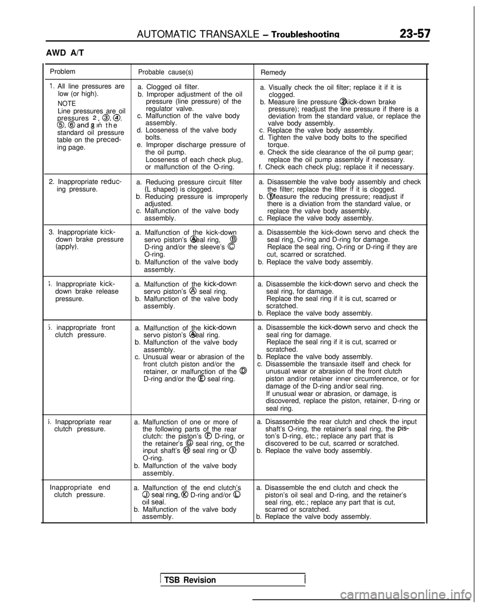
Problem
Probable cause(s)Remedy
1. All line pressures are a. Clogged oil filter.
low (or high). a. Visually check the oil filter; replace it if it is
b. Improper adjustment of the oil clogged.
NOTEpressure (line pressure) of the
b. Measure line pressure @ (kick-down brake
Line pressures are oil regulator valve.
pressure); readjust the line pressure if there is a
pressures
2 ,, 0, @,
8 c. Malfunction of the valve body
deviation from the standard value, or replace the0, @and 7 In th
e
assembly.
valve body assembly.
standard oil pressure d. Looseness of the valve body
c. Replace the valve body assembly.
table on the preced-
bolts.
d. Tighten the valve body bolts to the specified
ing page. e. Improper discharge pressure of
torque.
the oil pump. e. Check the side clearance of the oil pump gear;
Looseness of each check plug, replace the oil pump assembly if necessary.
or malfunction of the O-ring. f. Check each check plug; replace it if necessary.
2. Inappropriate reduc-
a. Reducing pressure circuit filter a. Disassemble the valve body assembly and check
ing pressure.
(L shaped) is clogged. the filter; replace the filter if
it is clogged.b. Reducing pressure is improperly b. @ Measure the reducing pressure; readjust if
adjusted. there is a diviation from the standard value, or
c. Malfunction of the valve body replace the valve body assembly.
assembly. c. Replace the valve body assembly.
3. Inappropriate kick-
a. Malfunction of the kick-down a. Disassemble the kick-down servo and check the
down brake pressure servo piston’s @ seal ring,
43seal ring, O-ring and D-ring for damage.
(appb).D-ring and/or the sleeve’s 0Replace the seal ring, O-ring or D-ring if they are
O-ring. cut, scarred or scratched.
b. Malfunction of the valve body b. Replace the valve body assembly.
assembly.
1. Inappropriate kick-
down brake release
pressure. a. Malfunction of the kickdownservo piston’s @
seal ring.
b. Malfunction of the valve body assembly. a. Disassemble the kickdown servo and check the
seal ring, for damage. Replace the seal ring if it is cut, scarred or
scratched.
b. Replace the valve body assembly.
j. inappropriate front clutch pressure. a. Malfunction of the kickdowna. Disassemble the kickdown servo and check the
servo piston’s @ seal ring.
seal ring for damage.
b. Malfunction of the valve body Replace the seal ring if it is cut, scarred or
assembly. scratched.
c. Unusual wear or abrasion of the b. Replace the valve body assembly.
front clutch piston and/or the c. Disassemble the transaxle itself and check for
retainer, or malfunction of the
0unusual wear or abrasion of the front clutch
D-ring and/or the @
seal ring. piston and/or retainer inner circumference, or for
damage of the D-ring and/or seal ring.
If unusual wear or abrasion, or damage, is
discovered, replace the piston, retainer, D-ring or
seal ring.
j. Inappropriate rear clutch pressure. a. Malfunction of one or more of
the following parts of the rearclutch: the piston’s
@I D-ring, or
the retainer’s 68 seal ring, or the
input shaft’s @I seal ring or @
O-ring.
b. Malfunction of the valve body assembly. a. Disassemble the rear clutch and check the input
shaft’s O-ring, the retainer’s seal ring, the pis-
ton’s D-ring, etc.; replace any part that is
discovered to be cut, scarred or scratched.
b. Replace the valve body assembly.
Inappropriate end clutch pressure. a. Malfunction of the end clutch’s
($ z;ea/,ring, @I D-ring and/or 0
b. Malfunction of the valve body
assembly. a. Disassemble the end clutch and check the
piston’s oil seal and D-ring, and the retainer’s
seal ring, etc.; replace any part that is cut,
scarred or scratched.
b. Replace the valve body assembly.
1 TSB Revision
Page 764 of 1273
23-58AUTOMATIC TRANSAXLE - Troubleshooting
Problem
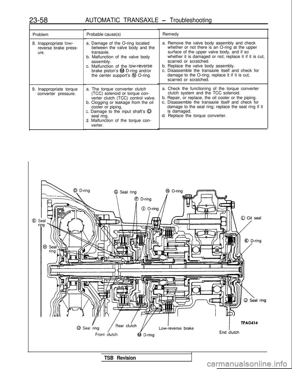
8. Inappropriate low-
reverse brake press-
ure.
9. Inappropriate torque converter pressure. Probable cause(s)
a. Damage of the O-ring located between the valve body and the
transaxle.
b. Malfunction of the valve body
assembly.
c. Malfunction of the
lo&reversebrake piston’s @I D-ring and/or
the center support’s @I O-ring.
a. The torque converter clutch (TCC) solenoid or torque con-
verter clutch (TCC) control valve.
b. Clogging or leakage from the oil
cooler or piping.
c. Damage to the input shaft’s @
seal ring.
d. Malfunction of the torque con-
verter. Remedy
a. Remove the valve body assembly and check whether or not there is an O-ring at the upper
surface of the upper valve body, and if so
whether it is damaged or not; replace it if it is cut,
scarred or scratched.
b. Replace the valve body assembly.
c. Disassemble the transaxle itself and check for damage to the O-ring; replace it if it is cut,
scarred or scratched.
a. Check the functioning of the torque converter clutch system and the TCC solenoid.
b. Repair, or replace, the oil cooler or the piping.
c. Disassemble the transaxle itself and check for damage to the seal ring; replace the seal ring if itis damaged.
d. Replace the torque converter.
TSB Revision
Page 788 of 1273
23-82AUTOMATIC TRANSAXLE - Service Adjustment Procedures
HOTTFA0715
AWD
LT FA0700J
SERVICE ADJUSTMENT PROCEDUR&g
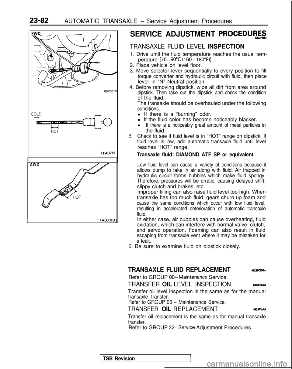
TRANSAXLE FLUID LEVEL INSPECTION
1. Drive until the fluid temperature reaches the usual tem-
perature [70-80°C
(160- 18O”F)I.
2. Place vehicle on level floor.
3. Move selector lever sequentially to every position to fill
torque converter and hydraulic circuit with fluid, then place
lever in “N” Neutral position.
4. Before removing dipstick, wipe all dirt from area around
dipstick. Then take out the dipstick and check the condition
of the fluid.
The transaxle should be overhauled under the following
conditions.
l If there is a “burning” odor.
l If the fluid color has become noticeably blacker.
l
If there is a noticeably great amount of metal particles in
the fluid.
5.Check to see if fluid level is in “HOT” range on dipstick. If
fluid level is low, add automatic transaxle fluid until level
reaches “HOT” range.
Transaxle fluid: DIAMOND ATF SP or equivalent
Low fluid level can cause a variety of conditions because it
allows pump to take in air along with fluid. Air trapped in hydraulic circuit forms bubbles which make fluid spongy.
Therefore, pressures will be erratic, causing delayed shift,
slippy clutch and brakes, etc.
Improper filling can also raise fluid level too high. When
transaxle has too much fluid, gears churn up foam and
cause the same conditions which occur with low fluid level, resulting in accelerated deterioration of automatic transaxle
fluid.
In either case, air bubbles can cause overheating, fluid
oxidation, which can interfere with normal valve, clutch,
and servo operation. Foaming can also result in fluid
escaping from transaxle vent where it may be mistaken for
a leak.
6. Be sure to examine fluid on dipstick closely.
TRANSAXLE FLUID REPLACEMENTM23FcsGa
Refer to GROUP 00-Maintenance
Service.
TRANSFER OIL LEVEL INSPECTIONMm=xM
Transfer oil level inspection is the same as for the manual
transaxle transfer.
Refer to GROUP 00
- Maintenance Service.
TRANSFER OIL REPLACEMENTM23FYAA
Transfer oil replacement is the same as for manual transaxle
transfer.
Refer to GROUP 22-Service
Adjustment Procedures.
TSB Revision
Page 794 of 1273
23-88AUTOMATIC TRANSAXLE - Service Adjustment Procedures
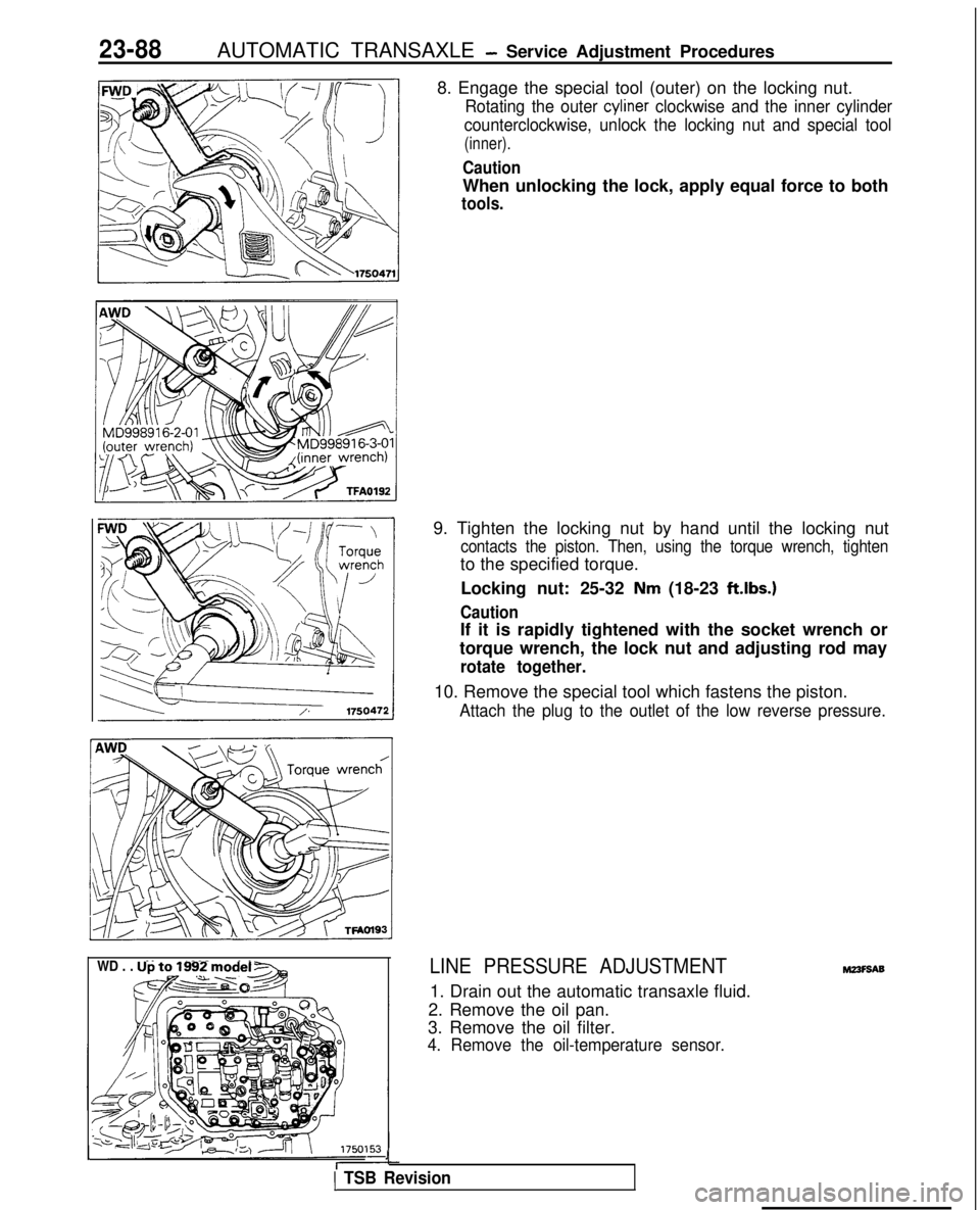
8. Engage the special tool (outer) on the locking nut.
Rotating the outer cyliner clockwise and the inner cylinder
counterclockwise, unlock the locking nut and special tool
(inner).
Caution
When unlocking the lock, apply equal force to both
tools.
WD . . . Up to 1992 model -
&@~o-&q
9. Tighten the locking nut by hand until the locking nut
contacts the piston. Then, using the torque wrench, tighten
to the specified torque.
Locking nut: 25-32
Nm (18-23 ft.lbs.)
Caution
If it is rapidly tightened with the socket wrench or
torque wrench, the lock nut and adjusting rod may
rotate together.
10. Remove the special tool which fastens the piston.
Attach the plug to the outlet of the low reverse pressure.
LINE PRESSURE ADJUSTMENT
1. Drain out the automatic transaxle fluid.
2. Remove the oil pan.
3. Remove the oil filter.
4. Remove the oil-temperature sensor.
J
1 TSB Revision
M23F9A9