1989 MITSUBISHI GALANT low oil pressure
[x] Cancel search: low oil pressurePage 458 of 1273
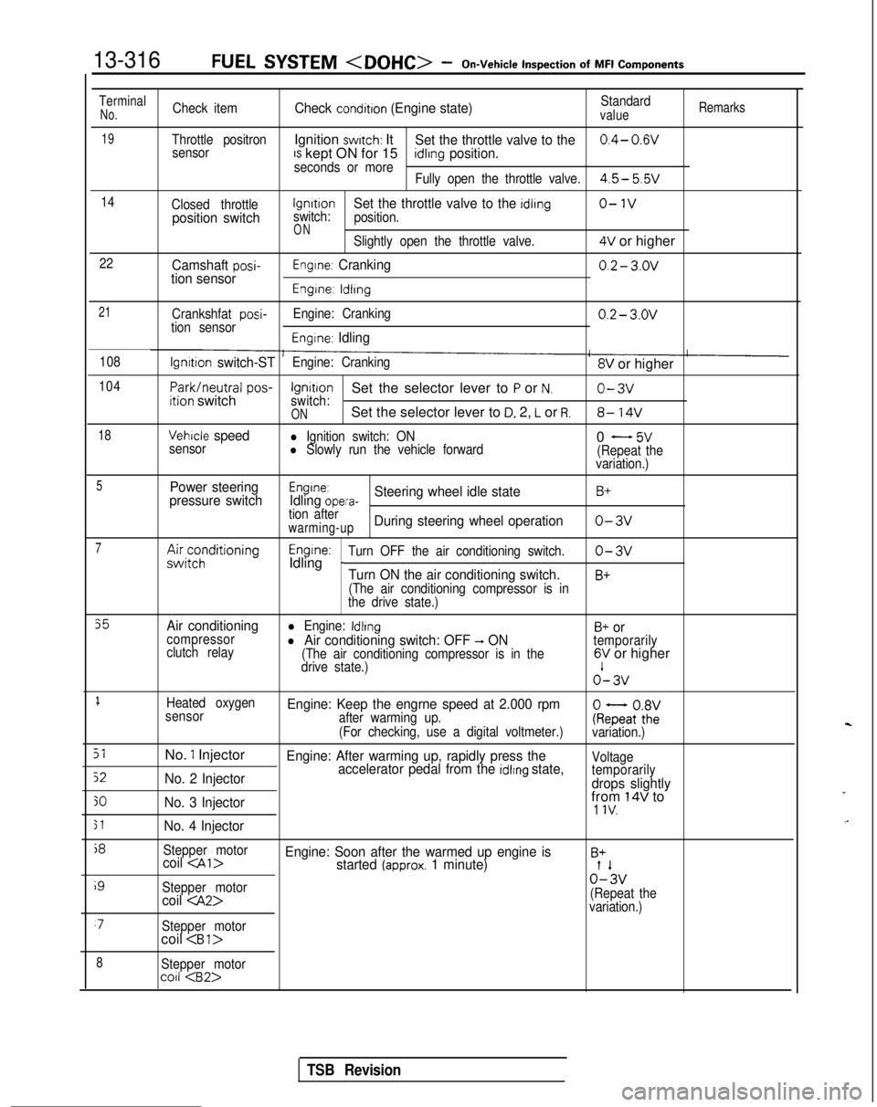
13-316FUEL SYSTEM
Inspection
of
MFI
Components
TerminalNo.Check itemCheck condition (Engine state)Standardvalue
Remarks
19Throttle positronIgnition switch: ItSet the throttle valve to the0.4- 0.wsensorIS kept ON for 15seconds or moreidlrng position.
Fully open the throttle valve.4.5- 5.5v
14
Closed throttlelgnrtrono-1vposition switchswitch:Set the throttle valve to the idling
position.
ONSlightly open the throttle valve.4V or higher
22Camshaft posi-tion sensorEngine: Cranking0.2- 3.ov
Engine: ldlrng
21
Crankshfat posi-tion sensor Engine: Cranking0.2- 3.ov
Engine: Idling
108lgnrtion switch-STEngine: Cranking8V or higher
104
Park/neutral
pos-ition switchIgnitionSet the selector lever to P or N.o-3vswitch:ONSet the selector lever to D, 2, L or R.8- 14V
18Vehicle speedl Ignition switch: ON
sensorl Slowly run the vehicle forward0 - 5v(Repeat the
variation.)
5Power steering
pressure switchEngine:Idling opera-Steering wheel idle stateB+
tion afterwarming-upDuring steering wheel operationo-3v
7A&;;;ditioningEngine:Idling _Turn OFF the air conditioning switch.o-3v
Turn ON the air conditioning switch.B+
(The air conditioning compressor is in
the drive state.)
35Air conditioningl Engine: IdlingB+ orcompressor
clutch relayl Air conditioning switch: OFF -, ON(The air conditioning compressor is in the
temporarily
drive state.)6V or higher o’-
3v
1Heated oxygen
sensorEngine: Keep the engrne speed at 2.000 rpmafter warming up.
(For checking, use a digital voltmeter.)ke;atoZivariation.)
51No. 1 InjectorEngine: After warming up, rapidly press the
52No. 2 Injector accelerator pedal from the idlrng state,Voltage
temporarily
drops slightly
30No. 3 Injectorfrom 14V to1 IV.
51No. 4 Injector
j8
Stepper motorcoil
i9
Stepper motor0%
coil
variation.)
‘7Stepper motorcoil
8Stepper motorco11
TSB Revision
Page 555 of 1273

COOLING- Specifications14-3
Items Specifications
Engine coolant temperature gauge unit ResistanceAt
70°C (158°F)n 104f13.5
Engine coolant temperature sensor (Engine control) ResistanceAt
20°C (68°F)kQ 2.45 f 0.24
At 80°C (176°F)Q 296+32
Air conditioning engine coolant temperature switch
ON
+ OFF operating temperature“C (“F) 112-118 (234-244
)
Engine coolant temperature switch
(Air conditioning or A/T control)
OFF
+ ON operating temperature“C (“F) 100-104 (212-219
)
Limit
Opening pressure of radiator cap high pressure valvekPa (psi) 65 (9.2)
TORQUE SPECIFICATIONS
MWCG-
ItemsNm ft.lbs.
Radiator upper insulator 9-14
7-10
Reserve tank, bracket installation bolt9-1
4
7-10
Thermosensor to radiator35
25
Automatic transaxle oil coole: hose cramp 4-
6
3-4
Automatic transaxle oil cooler hose mounting bolt 3-5
2-4
Water outlet fitting bolts
17-2012-14
Water inlet fitting bolts
IO-157-10
Engine mount insulator nut (large)60-8043-58
Engine mount insulator nut (small)
\ 30-4022-29
Engine mount bracket to engine
50-6536-47
Bracket between engine mount bracket and engine 17-26
12-19
Water pump installation bolt Bolt head mark “4T”
12-15
9-l 1
Bolt head mark “7T”20-2714-20
dater pump pulley bolt8-106-
7
Jamper pulley, crankshaft pulley20-3014-22
Timing belt front upper cover installation bolt
IO-127-
9
Timing belt front lower cover installation bolt
IO-127-
9
Crankshaft
sprocket installation bolt
110-13080-94
Timing belt B tensioner 15-2211-16
Tension pulley bracket for air conditioning
23-2717-20
Automatic tensioner installation bolt20-2714-20
Tensioner pulley installation bolt43-5531-40
Oil level gauge 12-159-l 1
Front exhaust pipe to exhaust manifold
Front exhaust pipe bracket
30-4022-29
Exhaust manifold cover (A), (B)
9-11
Heat protector
TSB Revision
Page 630 of 1273
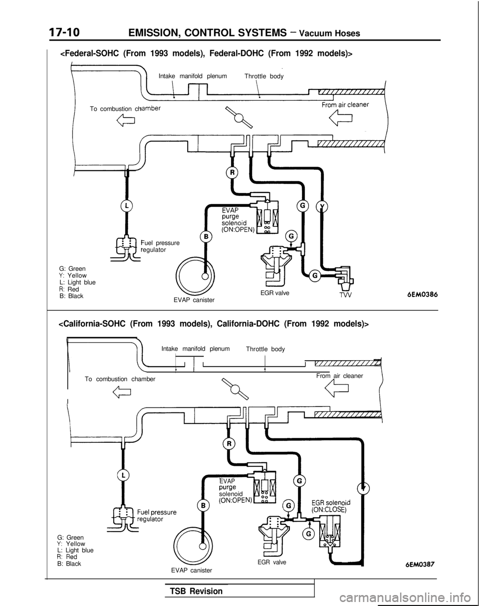
17-10EMISSION, CONTROL SYSTEMS - Vacuum Hoses
Intake manifold plenumThrottle body
To combustion ch
G: Green
Y: Yellow
L: Light blue
R: Red
B: Black Fuel pressure
regulator
EGR valve
EVAP canister6EM0386
Intake manifold plenum Throttle body,
II ) I I v///////i////1
To combustion chamber From air cleaner
I
G: Green
Y: Yellow
L: Light blue
D. 0,.,-dI,. IIC”B: Black pressul
ilatorre
EVAP purge
solenoid (0N:OPE
oil
El
EGR valve6EM0387EVAP canister
TSB Revision
Page 726 of 1273
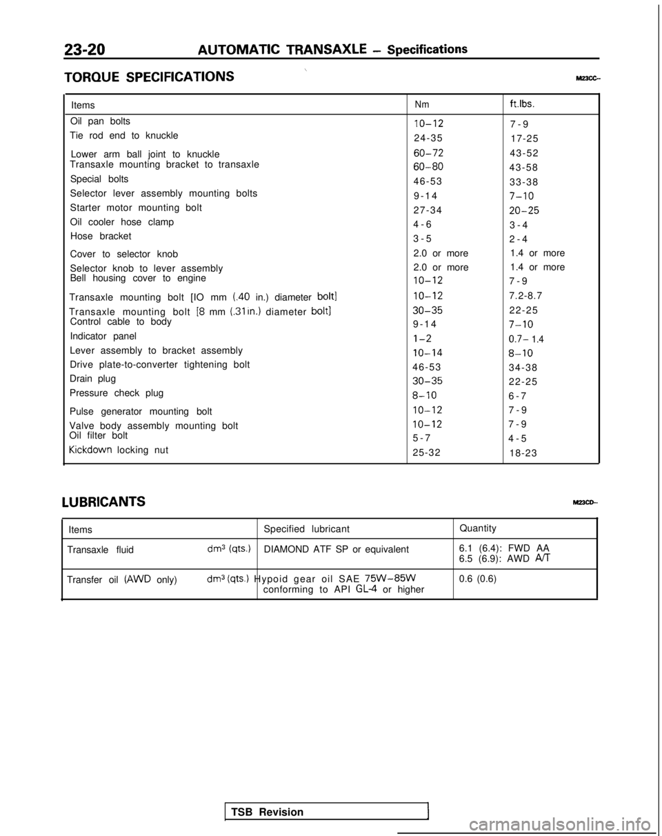
23-20AUTOMATIC TRANSAXLE
- Specifications
\TORQUE
SPECIFICATIONSMz3cc-
ItemsNmft.lbs.
Oil pan bolts10-127-
9
Tie rod end to knuckle 24-3517-25
Lower arm ball joint to knuckle
60-7243-52
Transaxle mounting bracket to transaxle
60-8043-58
Special bolts 46-5333-38
Selector lever assembly mounting bolts 9-1
4
7-10
Starter motor mounting bolt
27-3420-25
Oil cooler hose clamp4-
6
3-4
Hose bracket 3-52-4
Cover to selector knob 2.0 or more
1.4 or more
Selector knob to lever assembly 2.0 or more
1.4 or more
Bell housing cover to engine
10-127-
9
Transaxle mounting bolt [IO mm
(.40 in.) diameter bolt110-127.2-8.7
Transaxle mounting bolt
[8 mm (.31 In.) diameter bolt130-3522-25
Control cable to body 9-1
4
7-10
Indicator panell-20.7- 1.4
Lever assembly to bracket assembly10-148-10
Drive plate-to-converter tightening bolt
46-5334-38
Drain plug
30-3522-25
Pressure check plug
8-106-
7
Pulse generator mounting bolt
IO-127-
9
Valve body assembly mounting bolt
IO-127-
9
Oil filter bolt 5-74-5Kickdown
locking nut
25-3218-23LUBRICANTS
MPCD--
Items
Transaxle fluid Specified lubricant
Quantity
dm3 (qts.)DIAMOND ATF SP or equivalent6.1 (6.4): FWD AA
6.5 (6.9): AWD PJT
Transfer oil (AWD only)dm3 (qts.) Hypoid gear oil SAE 75W-85Wconforming to API GL-4 or higher0.6 (0.6)
TSB Revision
Page 728 of 1273
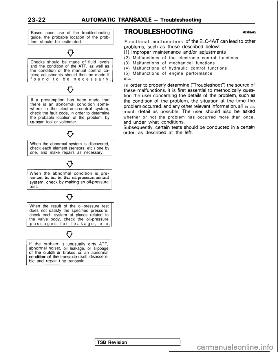
23-22 AUTOMATIC
TRANSAXLE
- Troubleshooting
Based upon use of the troubleshooting
guide, the probable location of the prob-
lem should be estimated.
Checks should be made of fluid levels
and the condition of the ATF, as well as
1 found to be necessary
.
the condition of the manual control ca-
bles; adjustments should then be made if
If a presumption has been made that
there is an abnormal condition some-
where in the electronic-control system,
check the fault code, in order to determine
the probable location of the problem, by using a scan tool or voltmeter.
When the abnormal system is discovered,
check each element (sensors, etc.) one by
one, and make repairs as necessary.
When the abnormal condition is pre- sumed to be in the oil-pressure-control
When the result of the oil-pressure test does not satisfy the specified pressure,
1 passages for leakage, etc
.
check each system at places related to
the valve body, check the oil-pressure
If the problem is unusually dirty ATF,
abnormal noises, oil leakage, or slippage
L##t he traniaxle.1
of the clutch or brakes or an abnormal
condition of the transaxle Itself,
disassem-
TROUBLESHOOTING
Functional malfunctions of the ELGWT can lead to other
problems,
such
as those described
below:
(1) Improper
maintenance
and/or
adjustments
(2) Malfunctions of the electronic control functions
(3) Malfunctions of mechanical functions
(4) Malfunctions of hydraulic control functions
(5) Malfunctions of engine performance
etc.
In order
to properly
determine (“Troubleshoot”)
the
source
of
these
malfunctions,
it is first essential
to methodically ques-
tion
the
user
concerning
the details
of the problem,
such as
the
condition of
the
problem,
the
situation at
the
time the
problem
occurred,
and any other relevant
information, all in as much detail
as possible.
The user
should
also be asked
whether or not the problem has occurred more than once,
and under
what conditions. Subsequently,
certain
tests should
be conducted in a certain
order,
as described
at
the
left.
1 TSB Revision
Page 741 of 1273
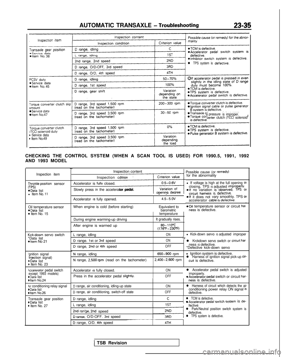
AUTOMATIC TRANSAXLE - Troubleshooting23-35
l TPS system isdefective.
ilpressure
is improper.verter clutch (TCC) solenoid
B Service datam Item No.49
CHECKING THE CONTROL SYSTEM (WHEN A SCAN TOOL IS USED) FOR 1990.5, 199\
1, 1992
AND 1993 MODEL
Inspection item
;;;yle posrtion sensor *Data
list
l Item No. 11
Oil temperature sensor *Data
list
0 Item No. 15
Krck-down servo switch
*Data list
*Item No 21
‘gnition signalInjectron signal) ,Data
list
D Item No. 23
iccelerator pedal switchexcept 1993 models)~Data listbItem No.24
Qr conditioning relay signalrData list rltem
No.26
Transaxle gear position~Data listm Item No. 27
-rInspection content
Inspection condition
Accelerator is
fullv closed.
LSlowly press in the accelerator pedal.
1 Possible cause (or remedy)for the abnormality
l If voltage is high at the full opening 01closing, TPS IS adjusted improperlv.elf no variation is observed. TPS 01
Accelerator IS fully opened.
--circuit harness ic r(afndi
O,a “ClrULIIu.
4.5-5.ov*If it does not vary smoothly. TPS OII- .-d-L__.:__accelerator cable IS oerectrve.
When engine is cold (before starting)
Equivalent to*Oil temperature sensor or circuit barbarometricness is defective.
During engine warming-up driving
After engine is warmed uptemperature
It gradually rises.
80- 110°C(176”F-230°F)
L range, idling
D range. 1st or 3rd speed
D range, 2nd or 4th speed
ON
ON
OFFl Kick-down servo IS adjusted improperIv.l Krckdown servo switch or circurt barness IS defective.
*Defective kick-down servo
N range, idling
N range, 2.500 rpm (read on the tachometer)
650-900 rpm l Ignition system is defective. 2.400-2.600
rpml Harness of ignition signal pick-up cir-cuit is defective.
Accelerator
IS fully closed.
Press in the accelerator pedal
sliphtlv.I
ON
OFF
l Accelerator pedal switch is adjusted
improperly. *Accelerator
oedal switch or circuit har-ness is defective.
D range, air conditioning, idling-up state
D range, air conditioning, switch-off state
ON
OFF
l Harness of circuit which detects the airconditioning power relay ON signal isdefective.
D range, idling
L range, idling
Cl TCM is defective.r A~d~r~tnr nednl +witch svstem is de-
!IST, -;,,tl;;..- r..--. -.-.--..
-,---,.,.,.,.v.l Park/Neutral position switch system isdefective.2nd ran!ge. 2nd speed
D renqe. O/D-OFF. 3rd speedl TPS system is defective.-~~~~~D range, O/D. 4th speed4TH
1 TSB Revision
Page 742 of 1273
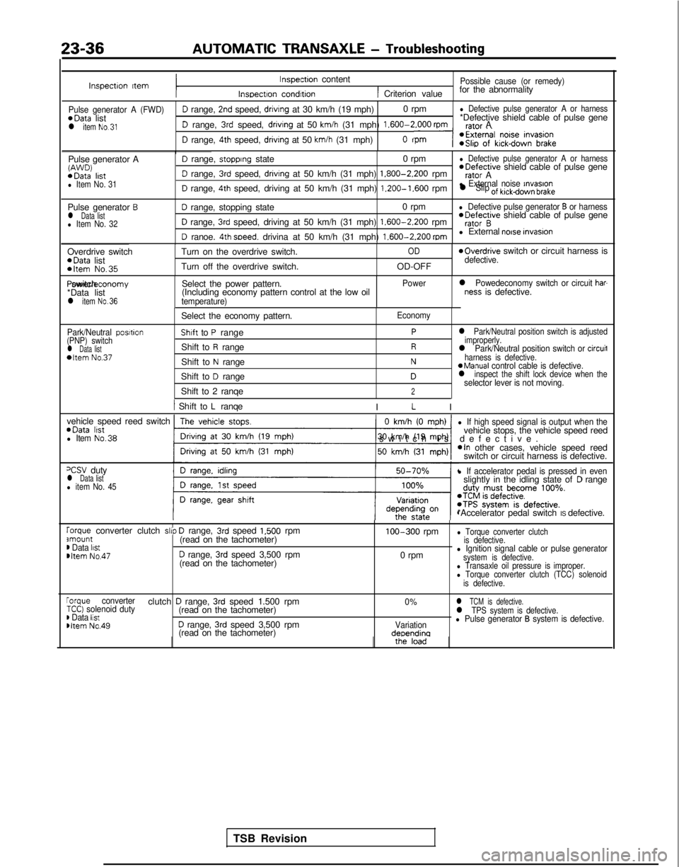
23-36AUTOMATIC TRANSAXLE
- Troubleshooting
Inspectron ItemInspection content
Inspectron condrtion
Possible cause (or remedy)
1 Criterion valuefor the abnormality
Pulse generator A (FWD)D range, 2nd speed, drivrng at 30 km/h (19 mph)
0 rpml Defective pulse generator A or harness*Data
list *Defective shield cable of pulse gene
l item No.31D range, 3rd speed, drivrng at 50 km/h (31 mph) 1.600-2.000
rpmrafnr A
D range, 4th speed, driving at 50 km/h (31 mph)n
Pulse generator AW’J’JD) *Data
lrstl Item No. 31
D range, stopprng state 0 rpml Defective pulse generator A or harness *Defective
shield cable of pulse gene
D range, 3rd speed, drivrng at 50 km/h (31 mph) 1.800-2.200
rpmrator A
D range, 4th speed, driving at 50 km/h (31 mph) 1.200-1.600
rpml External noise rnvasronl Slip of kickdown brake
Pulse generator Bl Data listl Item No. 32
D range, stopping state 0 rpml Defective pulse generator B or harness
D range, 3rd speed, driving at 50 km/h (31 mph) 1.600-2.200
rpm *Defective
shield cable of pulse generator B
D ranoe. 4th soeed. drivina at 50 km/h (31 mph) 1.600-2.200
mml External noise invasron
Overdrive switch *Data
list
*Item No.35
Turn on the overdrive switch.
Turn off the overdrive switch.OD
OD-OFF
moverdrive switch or circuit harness isdefective. Power/economy switch
*Data list
l item No.36
Select the power pattern.
(Including economy pattern control at the low oil
temperature) Power
l Powedeconomy switch or circuit har-ness is defective.
Park/Neutral posrtion
(PNP) switch
l Data list*Item No.37
Select the economy pattern.
Shaft to P range
Shift to
R range
Shift to
N range
Shift to
D range
Shift to 2 ranqe
Economy
Pl Park/Neutral position switch is adjusted
improperly.
Rl Park/Neutral position switch or circuil
Nharness is defective.aManual control cable is defective.Dl inspect the shift lock device when theselector lever is not moving.2
1 Shift to L ranqe
I L I
vehicle speed reed switch *Data
lrstl Item No.38
0 km/h (0 mph)
-1
l If high speed signal is output when thevehicle stops, the vehicle speed reed
switch is defective
.
*In other cases, vehicle speed reed
switch or circuit harness is defective.
=CSV dutyl Data listl item No. 45
l If accelerator pedal is pressed in evenslightly in the idling state ofD range
*Accelerator pedal switch IS defective.
rorque converter clutch slrp D range, 3rd speed 1,500 rpmamount(read on the tachometer)m Data listmltem No.47D range, 3rd speed 3,500 rpm
(read on the tachometer) 100-300
rpm
0 rpm
l Torque converter clutch
is defective.
l Ignition signal cable or pulse generatorsystem is defective.l Transaxle oil pressure is improper.l Torque converter clutch (TCC) solenoid
is defective.
rorque converterclutch D range, 3rd speed 1.500 rpm0%l TCM is defective.TCC) solenoid duty(read on the tachometer)) Data listl TPS system is defective.
Dltem No.49D range, 3rd speed 3,500 rpmVariationl Pulse generator B system is defective.
(read on the tachometer)deoendina
TSB Revision
Page 758 of 1273
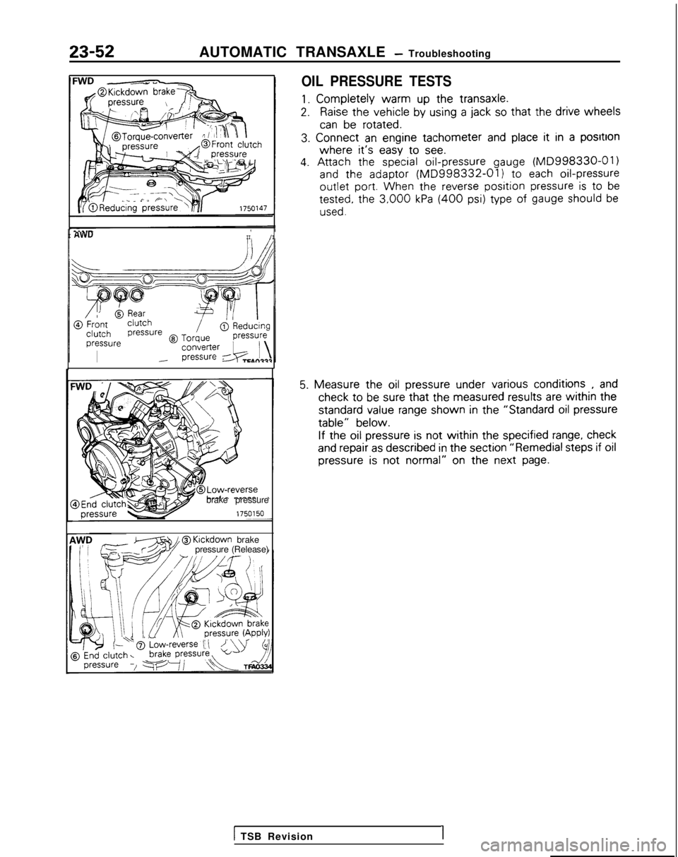
23-52AUTOMATIC TRANSAXLE - Troubleshooting
OIL PRESSURE TESTS
1. Completely
warm
up the
transaxle.
2.Raise the
vehicle
by
using
a jack so that the
drive
wheels
can be
rotated.
3.
Connect
an engine
tachometer
and place it
in a positron
where it’s easy
to
see.
4. Attach
the
special oil-pressure
gauge (MD998330-01)
and
the
adaptor
(MD998332-01) to
each oil-pressure
outlet
port. When
the
reverse position pressure is to
be tested,
the
3,000 kPa (400 psi) type
of gauge should be
used.
I AWUII/I
brake pressure
zT?ziw@
Klckdown
brake
pressure (Release)
5. Measure
the
oil pressure
under
various
conditions
, and check
to be sure that the
measured
results
are within the
standard
value
range shown
in the
“Standard
oil pressure
table”
below.
If the
oil pressure
is not
within the
specified
range, check
and repair
as described
in the
section
“Remedial
steps
if oil
pressure
is not
normal”
on the next
page.
1 TSB Revision1