1989 MITSUBISHI GALANT low oil pressure
[x] Cancel search: low oil pressurePage 340 of 1273
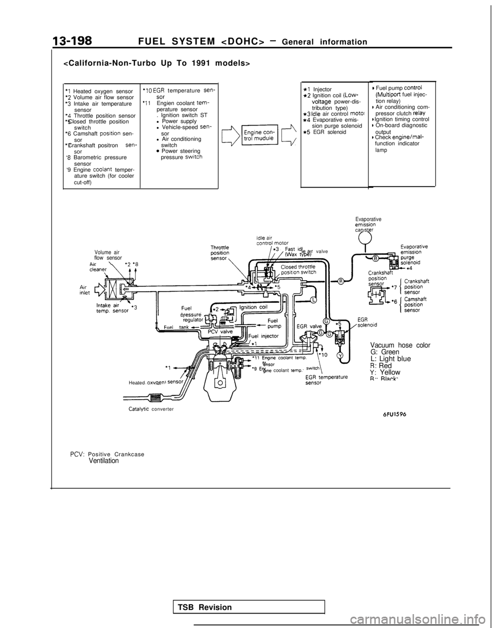
13-198FUEL SYSTEM
*I Heated oxygen sensor *IO
EGR temperature sen-*2 Volume air flow sensor
sor‘3 Intake air temperature
*I 1Engien coolant tem-sensor
perature sensor‘4 Throttle position sensor . Ignition switch ST*5 Closed throttle position
l Power supply
switch l Vehicle-speed sen-
‘6 Camshaft
posltion
sen- sor
sor l Air conditioning“7 Crankshaft positron sen-
switch
SOT0 Power steering‘8 Barometric pressure pressure switch
sensor
‘9 Engine coolant
temper-
ature switch (for cooler
cut-off)
*l Injector*2 Ignition coil (Low-
voltage
power-dis-
tribution type)
*3 idle air control mot01*4 Evaporative emis- sion purge solenoid
*5 EGR solenoid
) Fuel pump control
(Multiport
fuel injec-
tion relay)
I Air conditioning com- pressor clutch relay I Ignition timing control
) On-board diagnostic
output
) Check enginejmal-
function indicator
lamp
Evaporativeemissioncanister
Volume air
flow sensorA..\
II
oressure db,Fun, taw”l”‘“‘~
Heated 0~““~” le
ax valve
e”SOrgme coolant temp.
Vacuum hose color
G: Green
L: Light blueR: RedY: YellowR. Rlnrk
Catalytic converter 6FU1596
PCV:
Positive Crankcase
Ventilation
TSB Revision
Page 341 of 1273
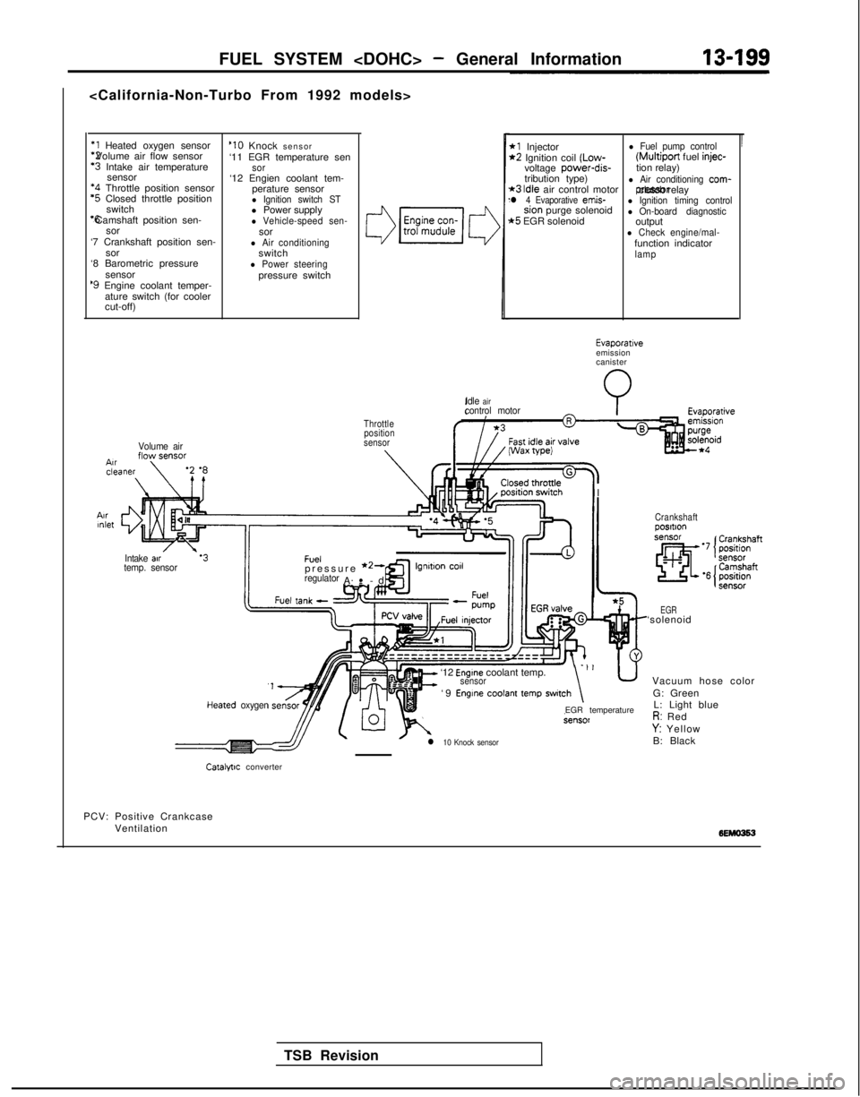
FUEL SYSTEM
*1 Heated oxygen sensor *2 Volume air flow sensor
‘3 Intake air temperature
sensor *4
Throttle position sensor
‘5 Closed throttle position
switch *6 Camshaft position sen-
sor
‘7 Crankshaft position sen- sor
‘8 Barometric pressure
sensor
‘9 Engine coolant temper-ature switch (for cooler
cut-off)
Volume air
‘10 Knock sensor
‘11 EGR temperature sen
sor‘12 Engien coolant tem- perature sensor
l Ignition switch STl Power supplyl Vehicle-speed sen-sorl Air conditioningswitchl Power steeringpressure switch
3
Throttleposition
sensor
IIntake air.‘3Fueltemp. sensorpressure *2-regulatorA-
-
.
cd
’
*l Injectorl Fuel pump control*2 Ignition coil (Low- (Multiport
fuel injec-voltage power-dis-
tion relay)
tribution type)
*3 Idle air control motorl Air conditioning com-
l 4 Evaporative emis- pressor clutch relaysion purge solenoidl Ignition timing control
t5 EGR solenoidl On-board diagnosticoutputl Check engine/mal-function indicatorlamp
Idle
aircontrol motorI Wax
wei
I
I
TSB Revision
Evaporativeemission
canister
Heared oxygen
It=
‘12 Engine coolant temp.sensor-‘I u
‘9 Engine coolant temp switch\
l 10 Knock sensor
EGR temperature
Crankshaftposltlon
EGR‘solenoid Vacuum hose colorG: GreenL: Light blue
R: RedY: Yellow
B: Black
Catalfllc converter
PCV: Positive Crankcase Ventilation
Page 342 of 1273
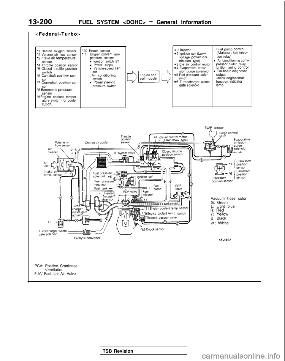
13-200FUEL SYSTEM
*l Heated oxygen sensor‘2 Volume air flow sensor*3 Intake air temperaturesensor‘4 Throttle position sensor‘5 Closed throttle positionswitch
*6
Camshaft posrtion sen-
sor
‘7 Crankshaft posrtion sen-
sor
‘8 Barometric pressuresensor “9
Engrne coolant temper-
ature swatch (for coolercut-off)
‘10 Knock sensor‘1 1Engien coolant
tem-perature sensorl lgnitton switch STl Power supplyl Vehicle-speed sen-sor. Arr conditioning
switch
l Power steeringpressure switch
Volume arrflow sensor
l 6
* 1 Injector. Fuel pump Control*2 Ignition coil (Low-(Multiport fuel injec-
voltage power-dis-tion relay)
tribution type) l Air conditioning com-
*3 Idle air control motor
pressor
clutch relay*4 Evaporative emis-
. Ignition timing control
sion purge solenoid l On-board diagnostic
*5 Fuel pressure sole-outputnoid. Check enginelmal-*6 Turbocharger wastegate solenoidf;r$ion indicator
EVAP canisterA
Throttle
9 Engine coolant temp. switch
Thermal VaCUUm valve
b;~ype; waste e-5 /I\- I”-
Catalyw converter
Vacuum hose color
G: Green
L: Light blue
R: RedY: Yellow
B: Black
W:
White
6FU1597
PCV: Positive CrankcaseVentilationFIAV Fast Idle Air Valve
I
TSB Revision
Page 343 of 1273
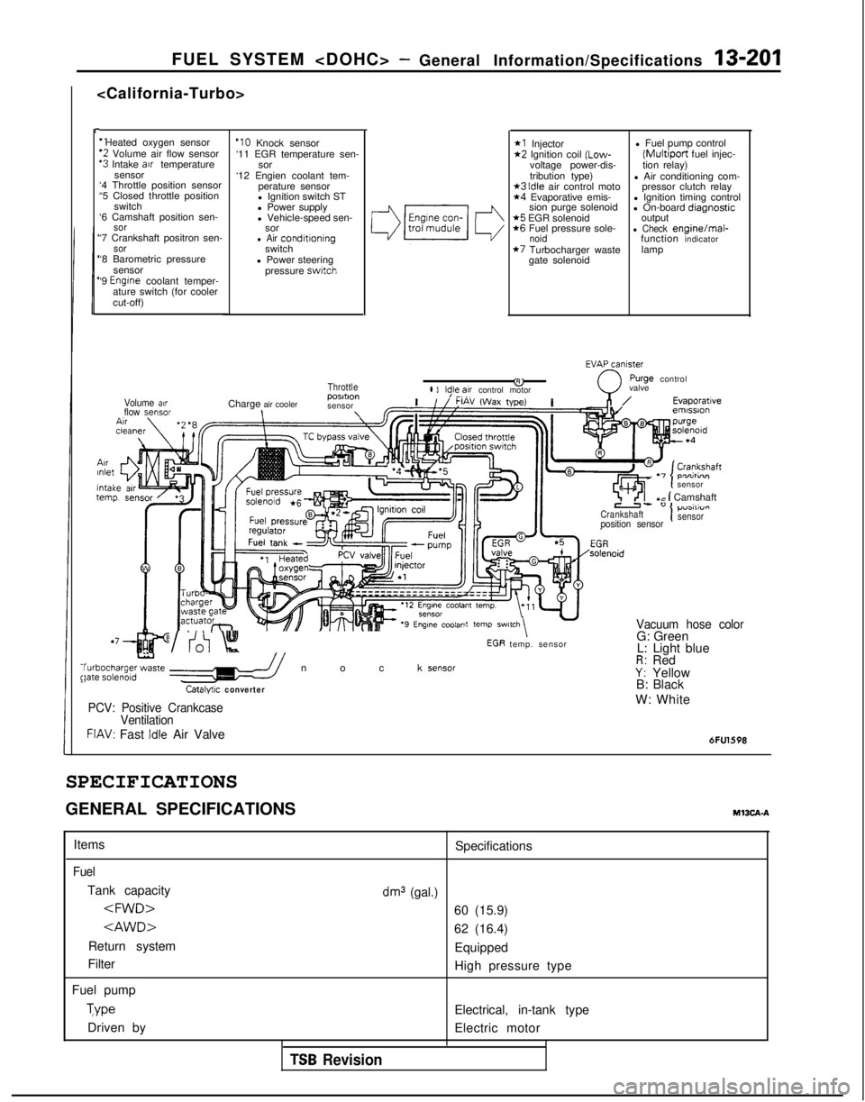
FUEL SYSTEM
I-
‘1 Heated oxygen sensor
‘2 Volume air flow sensor‘3 Intake arr temperature
sensor
‘4 Throttle position sensor
“5 Closed throttle position
switch
‘6 Camshaft position sen-
sor‘7 Crankshaft positron sen-sor‘8 Barometric pressure
sensor
‘9
Engrne coolant temper-
ature switch (for cooler
cut-off)
ArrInlet
lntaltern1
Volume airflow sensor
‘IO Knock sensor
‘11 EGR temperature sen- sor
‘12 Engien coolant tem- perature sensor
l Ignition switch ST
l Power supply
l Vehicle-speed sen- sor
l Air conditroningswitch
l Power steering pressure
swatch
Throttle
Charge air cooler posmon
sensor\\
*I Injector*2 Ignition coil (Low-
voltage power-dis-
tribution type)
*3 Idle air control moto*4 Evaporative emis- sion purge solenoid
*5 EGR solenoid*6 Fuel pressure sole-noid*7 Turbocharger waste
gate solenoid l Fuel pump control
(Multiport fuel injec-
tion relay)
l Air conditioning com- pressor clutch relay
l Ignition timing control
l On-board diaanostic
output
-l Check enginelmal-
function indicator
lamp
EVAxniy
&0
rurge controll 3ld,le,~ir control motor valve
,n/Evaporatrveemrssron
\tcln-^- temp. sensor
,Ir I-, . -,
sensor
7 ’ <‘I+c 1 Camshaft
Crankshaft1p”3111”I I
position sensorsensor
it
temp SWl,Ch\ -Vacuum hose color
t
WV:0 Knock sensor$bgha;ge;zte //
Catalyuc converter
G: Green
L: Light blue
R: RedY: Yellow
B: Black
PCV: Positive Crankcase
VentilationW: White
FIAV: Fast Idle Air Valve6FU1598
SPECIFICATIONS
GENERAL SPECIFICATIONSM13CA-A
Items
Fuel
Tank capacity
Return system
Filter
Fuel pump Type
Driven by Specifications
dm3 (gal.)
60 (15.9)
62 (16.4)
Equipped
High pressure type
Electrical, in-tank type
Electric motor
TSB Revision
Page 347 of 1273
FUEL SYSTEM
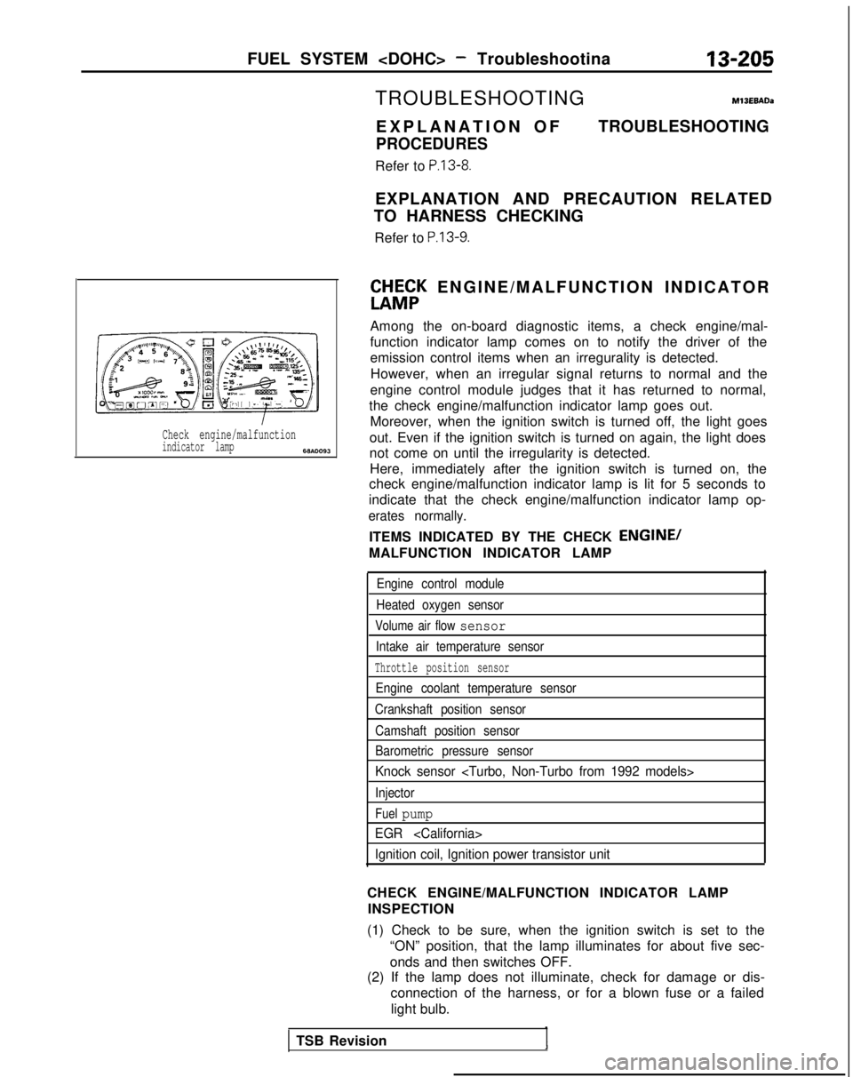
Check engine/malfunctionindicator lamp6w.0093
TROUBLESHOOTINGM13EBADa
EXPLANATION O
F
PROCEDURES
Refer to P.13-8.
TROUBLESHOOTING
EXPLANATION AND PRECAUTION RELATED
TO HARNESS CHECKING
Refer to
P.13-9.
ft&;K ENGINE/MALFUNCTION INDICATO
R
Among the on-board diagnostic items, a check engine/mal-
function indicator lamp comes on to notify the driver of the
emission control items when an irregurality is detected. However, when an irregular signal returns to normal and the
engine control module judges that it has returned to normal,
the check engine/malfunction indicator lamp goes out. Moreover, when the ignition switch is turned off, the light goes
out. Even if the ignition switch is turned on again, the light does
not come on until the irregularity is detected. Here, immediately after the ignition switch is turned on, the
check engine/malfunction indicator lamp is lit for 5 seconds to
indicate that the check engine/malfunction indicator lamp op-
erates normally.
ITEMS INDICATED BY THE CHECK ENGINE/
MALFUNCTION INDICATOR LAMP
Engine control module
Heated oxygen sensor
Volume air flow sensor
Intake air temperature sensor
Throttle position sensor
Engine coolant temperature sensor
Crankshaft position sensor
Camshaft position sensor
Barometric pressure sensor
Knock sensor
Injector
Fuel pump
EGR
Ignition coil, Ignition power transistor unit
CHECK ENGINE/MALFUNCTION INDICATOR LAMP INSPECTION
(1) Check to be sure, when the ignition switch is set to the “ON” position, that the lamp illuminates for about five sec-
onds and then switches OFF.
(2) If the lamp does not illuminate, check for damage or dis-
connection of the harness, or for a blown fuse or a failed
light bulb.
TSB Revision
Page 350 of 1273
13-208FUEL SYSTEM
No.
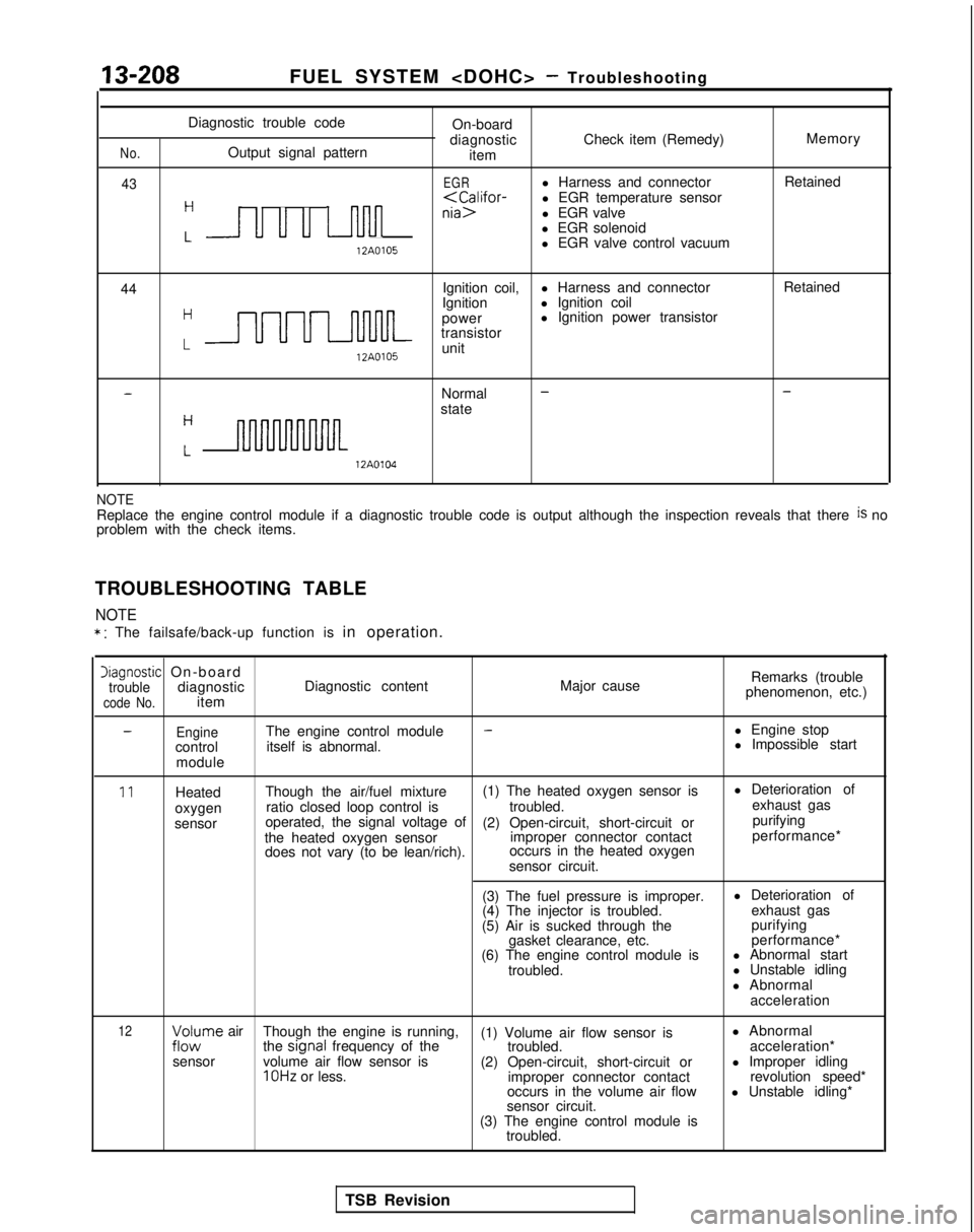
43
Diagnostic trouble codeOn-board
diagnostic Check item (Remedy) Memory
Output signal pattern item
EGRl Harness and connector Retained
H
nia>l EGR valve
l EGR solenoid
L 12A0105
l EGR valve control vacuum
44 Ignition coil,
l Harness and connector Retained
Hl Ignition coil
LUUULnl-lM-
Ignition
power l Ignition power transistor
transistor 12A0105
unit
-Normal --
stateH
Lnm 12A0104
NOTEReplace the engine control module if a diagnostic trouble code is output\
although the inspection reveals that there is no
problem with the check items.
TROUBLESHOOTING TABLE
NOTE
* : The failsafe/back-up function is in operation.
Diagnostic On-boardtroublediagnosticcode No.itemDiagnostic content
Major causeRemarks (trouble
phenomenon, etc.)
-EngineThe engine control module-l Engine stop
control itself is abnormal. l Impossible start
module
11Heated Though the air/fuel mixture (1) The heated oxygen sensor is l Deterioration of
oxygen ratio closed loop control is
troubled.exhaust gas
sensor operated, the signal voltage of
(2) Open-circuit, short-circuit or purifying
the heated oxygen sensor improper connector contactperformance*
does not vary (to be lean/rich). occurs in the heated oxygen
sensor circuit.
(3) The fuel pressure is improper. l Deterioration of
(4) The injector is troubled. exhaust gas
(5) Air is sucked through the purifying
gasket clearance, etc. performance*
(6) The engine control module is l Abnormal start
troubled. l Unstable idling
l Abnormal acceleration
12;zc$rne air Though the engine is running,
(1) Volume air flow sensor is l Abnormal
the signal
frequency of the
troubled. acceleration*
sensor volume air flow sensor is
(2) Open-circuit, short-circuit or l Improper idling
1 OHz or less.
improper connector contact revolution speed*
occurs in the volume air flow l Unstable idling*
sensor circuit.
(3) The engine control module is troubled.
TSB Revision
Page 352 of 1273
13-210FUEL SYSTEM
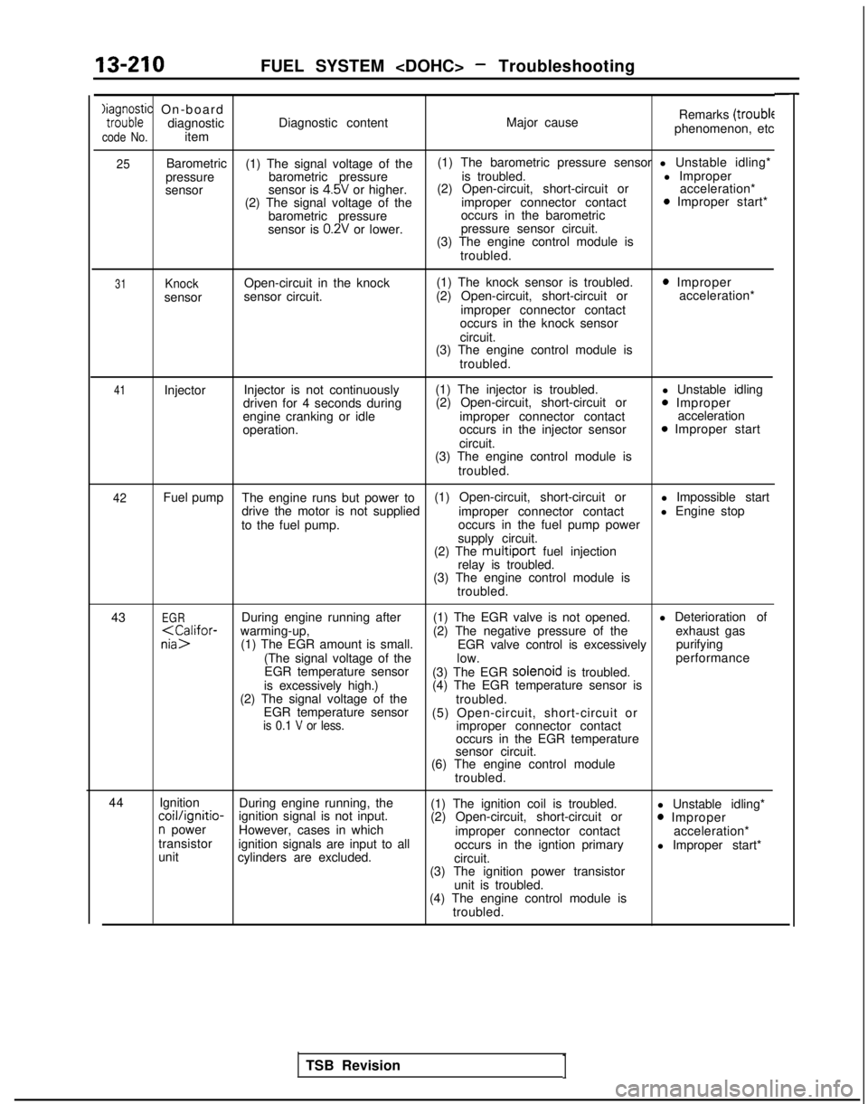
Xaia;;;ic On-boarddiagnostic
code No.item Diagnostic content
Major causeRemarks
(troublephenomenon, etc
25Barometric
(1) The signal voltage of the (1) The barometric pressure sensor l Unstable idling*
pressure barometric pressure is troubled. l Improper
sensor sensor is
4.5V or higher.(2) Open-circuit, short-circuit or
acceleration*
(2) The signal voltage of the improper connector contact0 Improper start*
barometric pressure occurs in the barometric
sensor is
0.2V or lower. pressure sensor circuit.
(3) The engine control module is
troubled.
31Knocksensor Open-circuit in the knock
sensor circuit. (1) The knock sensor is troubled.
(2) Open-circuit, short-circuit or
improper connector contact
occurs in the knock sensor
circuit.
0 Improper acceleration*
(3) The engine control module is troubled.
41Injector Injector is not continuously
driven for 4 seconds during
engine cranking or idle
operation. (1) The injector is troubled.
(2) Open-circuit, short-circuit or
improper connector contact
occurs in the injector sensor
circuit.
(3) The engine control module is
troubled. l Unstable idling0 Improper
acceleration
0 Improper start
42Fuel pump The engine runs but power to (1) Open-circuit, short-circuit or
l Impossible start
drive the motor is not supplied improper connector contactl Engine stop
to the fuel pump. occurs in the fuel pump power
supply circuit.
(2) The
multiport fuel injection
relay is troubled.
(3) The engine control module is
troubled.
43
EGRDuring engine running after (1) The EGR valve is not opened. l Deterioration of
EGR valve control is excessively purifying
(The signal voltage of the low. performance
EGR temperature sensor (3) The EGR solenoid
is troubled.
is excessively high.) (4) The EGR temperature sensor is
(2) The signal voltage of the troubled.
EGR temperature sensor (5) Open-circuit, short-circuit or
is 0.1 V or less.improper connector contact
occurs in the EGR temperature
sensor circuit.
(6) The engine control module
troubled.
44 Ignition
During engine running, the
(1) The ignition coil is troubled. l Unstable idling*
coil/ignitio-ignition signal is not input.
(2) Open-circuit, short-circuit or0 Impropern powerHowever, cases in which
improper connector contact acceleration*
transistor ignition signals are input to all
occurs in the igntion primaryl Improper start*
unit cylinders are excluded.
circuit.
(3) The ignition power transistor
unit is troubled.
(4) The engine control module is
troubled.
TSB Revision
1
Page 353 of 1273

FUEL SYSTEM
FAILSAFE/BACK-UP FUNCTIONS LIST
If trouble with any major sensor is detected by the on-board diagnostic,\
the vehicle will be kept in the safe
driving conditions-accdrding
to the preset control
logic.
Trouble item
Volume air flow
sensor Control content for trouble
(1) Fuel injection timing and ignition timing are determined according\
to the throttle positior
sensor (TPS) and engine revolution speed signal (crankshaft position \
sensor signal).
(2) The idle air control motor is fixed at the specified position, and\
the idle revolution speec
control is not executed.
Intake air
temperature sensor The control is executed with the suction air temperature regarded as
25’C (77°F).
Throttle positron
sensor (TPS)The fuel injection rate is not increased for acceleration according to t\
he throttle positionsensor signal.
Engine coolant
temperature sensor The control IS executed with the engine coolant temperature regarded as 80°C
(176°F).(Even if the sensor signal becomes normal again, the control is continu\
ed until the ignition
switch is turned off.)
Camshaft position
sensor (1) Simultaneous injection of fuel is executed for all cylinders.
(In this case, the No.
1 cylinder top dead center is not detected at all after the ignition
key is turned on.)
(2) Fuel is cut 4 seconds after trouble is detected. (In this case, the No. 1 cylinder top dead center IS not detected at all after the ignition
key is turned on.)
Barometric pressure
sensor The control is executed with the pressure regarded as 760
mmHg (30 in.Hg.).
Knocksensor
The ignition timing is retarded further from the normal state, and ignit\
ion is executed even
when knocking does not occur.
Ignition coil, ignition
power transistor unitFuel is cut in the cylinder where the ignition signal is abnormal.
Heated oxygen sensor Closed loop control of the air/fuel mixture ratio is not executed.
TSB RevisionREAD OUT OF DIAGNOSTIC TROUBLE CODE
Refer to
P.13-16.
CLEAR MEMORY OF DIAGNOSTIC TROUBLE
CODE
Refer to P.13-17.