1989 MITSUBISHI GALANT low oil pressure
[x] Cancel search: low oil pressurePage 354 of 1273
13-212
FUEL SYSTEM
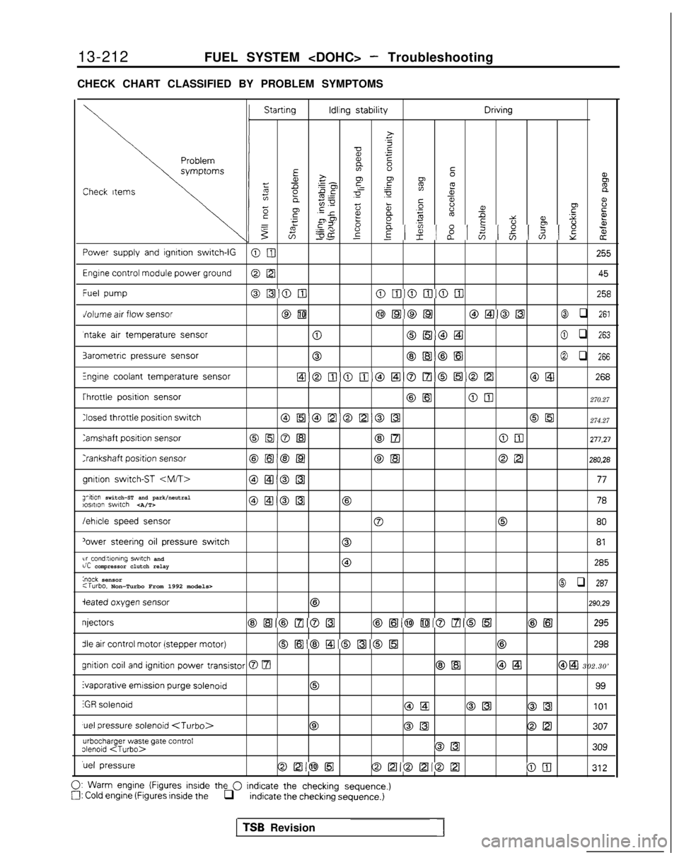
CHECK CHART CLASSIFIED BY PROBLEM SYMPTOMS Starting Idling
stability Driving
>
.c
zx .-
E
EE 2-80’
52FCheck
Itemsz gp ~ =
gif8e
5;ms00 a,L%a‘;E
2
F5i5 .-
5scp ‘-re,t2aDo’6%.fP .xz YPfbz 2 ‘5 uE22
%il= 5
8
8 8gzzg-c$z8
z
Power
supply
and
ignition switch-IGOnI
255
Engine
control
module power ground
@ [ZI
45
Fuel
pumpoI51oulolIioDloiIl258
Jolume
air
flow sensorcam@Ea@@l@EilO[41@ q 261
‘ntake
air
temperature sensor0OlEiiOEtl@ q 263
3arometric
pressure
sensor0@lB@El@ q 266
Fngine coolant temperature sensorEloiIlomoaol7loEloDO@ 268
Throttle
position
sensor
@[email protected]
Closed throttle
position
switch0[51@D@D0[[email protected]
Tamshaft position
sensorOrnOlsl@Elam277,27
Crankshaft
position
sensor@El@[email protected]
gnltion
switch-ST
anitlon switch-ST and park/neutral)os,t,on switch @ElODl@ 78
/ehlcle
speed
sensor
00
80
‘ower
steering
oil
pressure
switch081
w conditlonlng swtch andr/C compressor clutch relay0285
knock sensor:Turbo. Non-Turbo From 1992 models>@ q 287
ieated oxygen
sensor
@290.29
njectors
@,[Hl@lzl@lz3@,161@Di080151@El
295
die air
control
motor (stepper
motor)0[63@!zl@al0863298 gnition
coil
and ignition
power transistor 0 m@El @El@ a 302.30’ Evaporative emission
purge
solenoid
0
99
iGR
solenoid@LaOK3@II3101
uel
pressure
solenoid
urbocharger waste gate contrololenoid
309
‘uel
pressureOD@l5l@D@D012100
312
0:
Warm
engine (Figures
inside
the 0 indicate the checking sequence.)a: Cold engine (Figures
inside
the q indicate
the checking
sequence.)
TSB Revision1
Page 393 of 1273
FUEL SYSTEM
ON VEHICLE INSPECTION OF MFI COMPONENTS
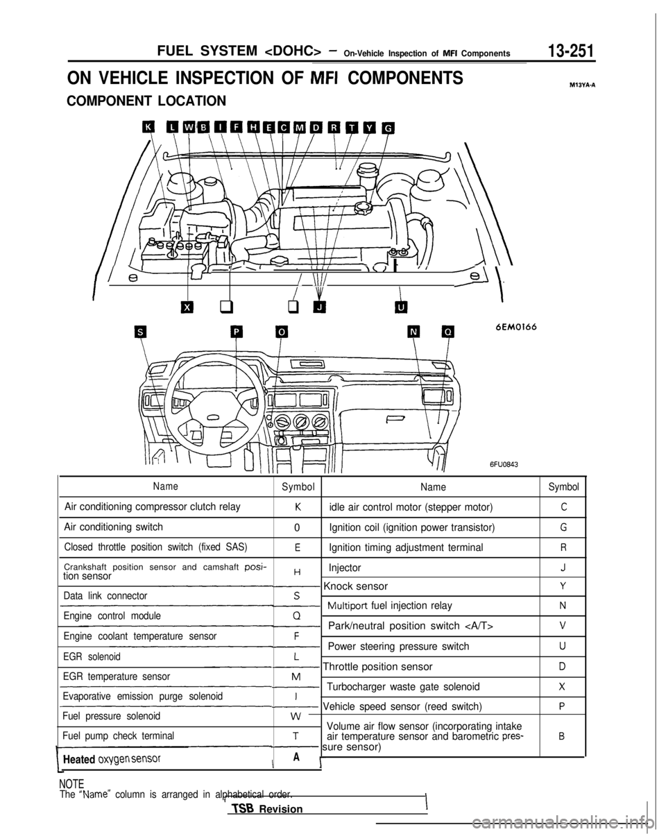
COMPONENT LOCATION
4 QCiW41QQWPQWQ
I l-+-Y8’
-,..I- - IIII\< I IJ I
/ \lI/--Gl/
El q
I &
q
‘\
P P
6EM0166
MIBYA-A
6FUO843
NameSymbol
NameSymbol
Air conditioning compressor clutch relayKidle air control motor (stepper motor)C
Air conditioning switch0Ignition coil (ignition power transistor)G
Closed throttle position switch (fixed SAS)EIgnition timing adjustment terminalR
Crankshaft position sensor and camshaft posi-HInjectorJtion sensor- Knock sensorYData link connectorS~Multiport
fuel injection relayNEngine control moduleQ-Park/neutral position switch vEngine coolant temperature sensorF-Power steering pressure switchUEGR solenoidL- Throttle position sensorDEGR temperature sensorM-Turbocharger waste gate solenoidXEvaporative emission purge solenoidI~ Vehicle speed sensor (reed switch)PFuel pressure solenoidwVolume air flow sensor (incorporating intakeFuel pump check terminalTair temperature sensor and barometric pres-B- sure sensor)
Heated
oxygen sensorIA I-
NOTE
The “Name” column is arranged in alphabetical order.II TSB
RevisionI
Page 403 of 1273
FUEL SYSTEM
VOLUME AIR FLOW SENSORMlWFAAs
/
side
@Harness side connector
I@ Harness sideconnector
Fnnine control module connector
Multiport fuel
The area enclosed with :I: is injection relay
applicable only for Turbo vehicle.
I
@I Component connector (Filter reset circuit)
Engine control module
6FU1537
Intake air amount (Wsec)
162451
OlLO838
OPERATION
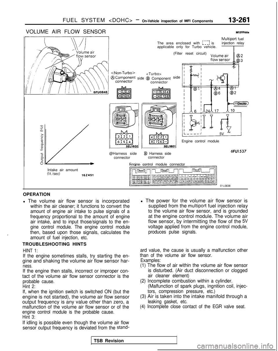
l The volume air flow sensor is incorporated
within the air cleaner; it functions to convert the
amount of engine air intake to pulse signals of a
frequency proportional to the amount of engine air intake, and to input those/signals to the en-
gine control module. The engine control module
then, based upon those signals, calculates the
amount of fuel injection, etc.
TROUBLESHOOTING HINTS
HINT 1:
If the engine sometimes stalls, try starting the en-
gine and shaking the volume air flow sensor har-
ness.
If the engine then stalls, incorrect or improper con-
tact of the volume air flow sensor connector is the
probable cause.
Hint 2:
If, when the ignition switch is switched ON (but the
engine is not started), the volume air flow sensor
output frequency is any value other than zero, a
malfunction of the volume air flow sensor or of the
engine control module is the probable cause.
Hint 3:
If idling is possible even though the volume air flow
sensor output frequency is deviated from the
stand-
l The power for the volume air flow sensor is supplied from the
multiport fuel injection relay
to the volume air flow sensor, and is grounded
at the engine control module. The volume air
flow sensor, by intermitting the flow of the
5V
voltage applied from the engine control module,
produces pulse signals.
ard value, the cause is usually a malfunction other
than of the volume air flow sensor. Examples:
(1) The flow of air within the volume air flow sensor
is disturbed. (Air duct disconnection or clogged
air cleaner element)
(2) Incomplete combustion within a cylinder.(Malfunction of spark plugs, ingnition coil, injec-
tors, compression pressure, etc.)
(3) Air is taken into the intake manifold through a
leaking gasket, etc.
(4) Incomplete close contact of the EGR valve seat.
TSB Revision
Page 427 of 1273
FUEL SYSTEM
AIR CONDITIONING SWITCH AND A/C COMPRESSOR CLUTCH RELAYmt3n7.4al
Jk: L 1 /J l-k~-~+ L!- Air conditioning switch
0
/’
’ ’ -~.i>
‘\ /,
(\ QeF --:
’ -q,,T
(‘a/ A-.,>*/ \
) !I/ ,+f---J;I’,,p
s- / :\,$jy W/’
\mc-- -; --
\\ \\$ &
IF -~1. bI /~-~ i E--z
\ \I i
!
L-,-1&L.- ~~~~.
6FUO845 I
Sub fusible link
‘7 IpI Z%37°GZressor
2 Dual pressure
switch
1
t
Air conditioning OFF
engif’Ie codant* temperatureON switc
h
T
2
TSB Revision
Engine control module
,(65 1\7
v v
Engine control module connector6FU1457
OlLo838
OPERATION
l
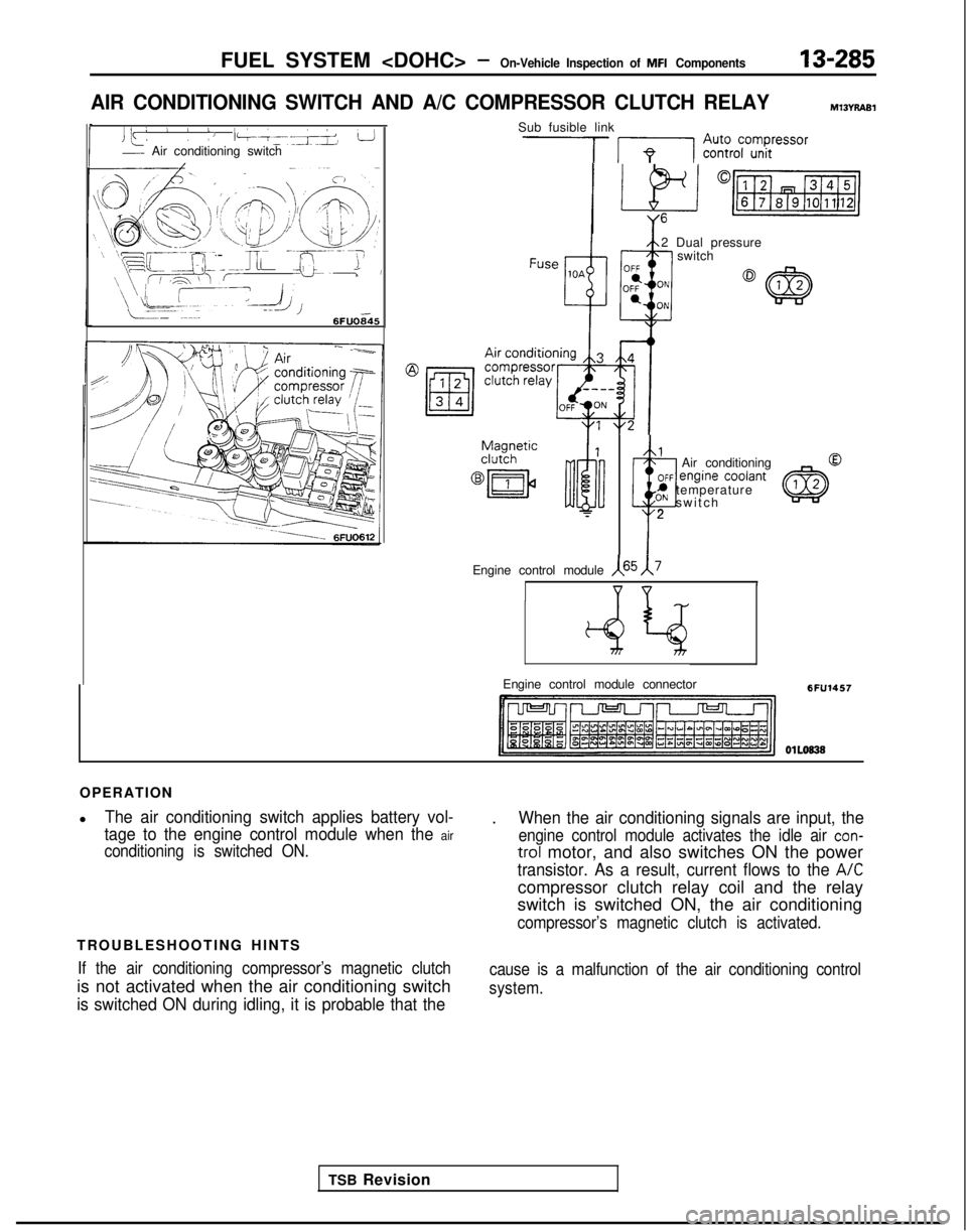
The air conditioning switch applies battery vol-
tage to the engine control module when the
air
conditioning is switched ON.
TROUBLESHOOTING HINTS
If the air conditioning compressor’s magnetic clutch
is not activated when the air conditioning switch
is switched ON during idling, it is probable that the
.When the air conditioning signals are input, the
engine control module activates the idle air con-
trol motor, and also switches ON the power
transistor. As a result, current flows to the A/C
compressor clutch relay coil and the relay
switch is switched ON, the air conditioning
compressor’s magnetic clutch is activated.
cause is a malfunction of the air conditioning control
system.
Page 437 of 1273
FUEL SYSTEM
of
MFI
Components13-295
Filter
Connector
Solenoid coil
Plunger
Needle valve -&$
lnjedtion6FUO51
Multiport
fuel injection relayMIBvrbA1
I
The area enclosed with ~~~~ is@I Harness side
applicable onlv for Turbo.
connector
Enginecofitrolmodule
Engine control module connectorI6FU1547
OlLo63
OPERATION
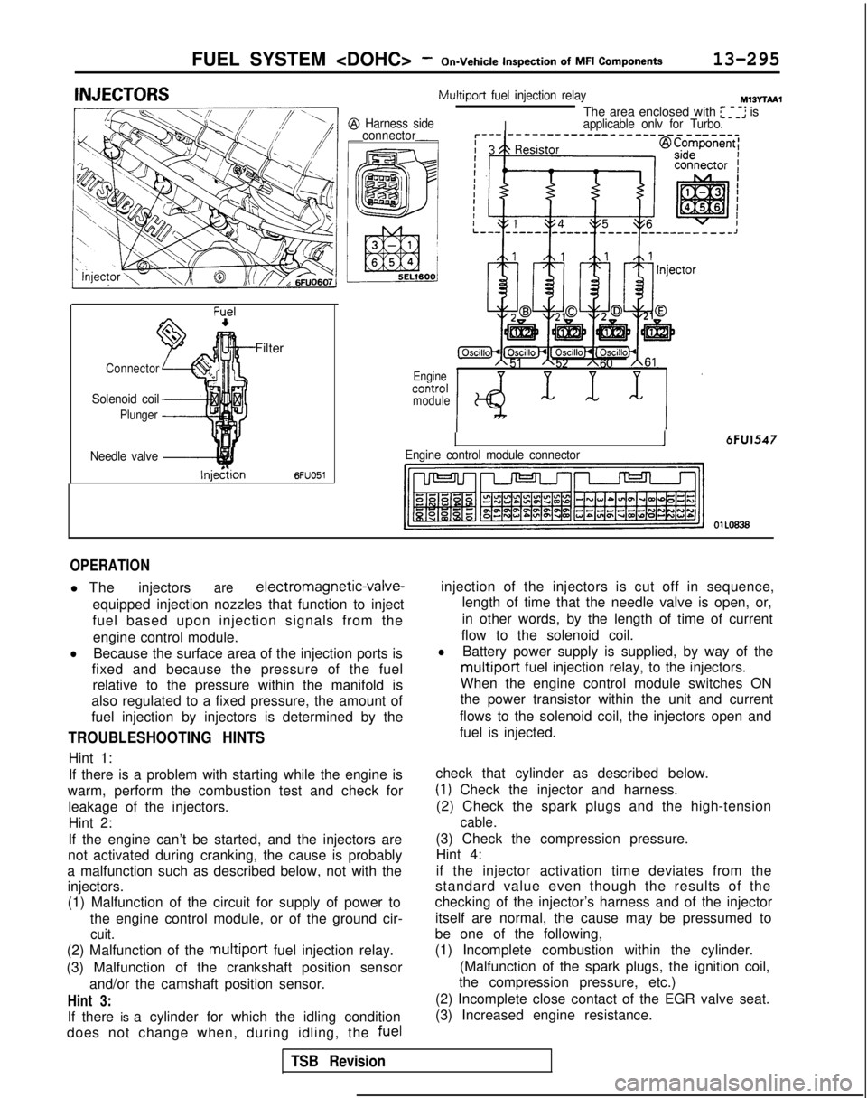
l The injectorsare electromagnetic-valve-
equipped injection nozzles that function to inject
fuel based upon injection signals from the engine control module.
lBecause the surface area of the injection ports is
fixed and because the pressure of the fuel relative to the pressure within the manifold is
also regulated to a fixed pressure, the amount of
fuel injection by injectors is determined by the
TROUBLESHOOTING HINTS
Hint 1:
If there is a problem with starting while the engine is
warm, perform the combustion test and check for leakage of the injectors.Hint 2:
If the engine can’t be started, and the injectors are
not activated during cranking, the cause is probably
a malfunction such as described below, not with the injectors.
(1) Malfunction of the circuit for supply of power to
the engine control module, or of the ground cir-
cuit.
(2) Malfunction of the multiport fuel injection relay.
(3) Malfunction of the crankshaft position sensor and/or the camshaft position sensor.
Hint 3:
If there is a cylinder for which the idling condition
does not change when, during idling, the fuelinjection of the injectors is cut off in sequence,
length of time that the needle valve is open, or,
in other words, by the length of time of current
flow to the solenoid coil.
lBattery power supply is supplied, by way of the
multiport fuel injection relay, to the injectors.
When the engine control module switches ON
the power transistor within the unit and current
flows to the solenoid coil, the injectors open and
fuel is injected.
check that cylinder as described below.
(1) Check the injector and harness.
(2) Check the spark plugs and the high-tension
cable.
(3) Check the compression pressure. Hint 4:
if the injector activation time deviates from the
standard value even though the results of the
checking of the injector’s harness and of the injector
itself are normal, the cause may be pressumed to
be one of the following,
(1) Incomplete combustion within the cylinder.
(Malfunction of the spark plugs, the ignition coil,
the compression pressure, etc.)
(2) Incomplete close contact of the EGR valve seat.
(3) Increased engine resistance.
TSB Revision
Page 441 of 1273
FUEL SYSTEM
MFI Components13-299
OPERATION
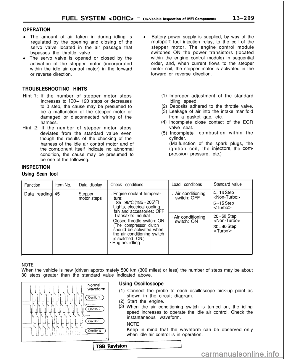
l The amount of air taken in during idling is
regulated by the opening and closing of the
servo valve located in the air passage that
bypasses the throttle valve.
l The servo valve is opened or closed by the
activation of the stepper motor (incorporated
within the idle air control motor) in the forward
or reverse direction.
TROUBLESHOOTING HINTS
Hint 1: If the number of stepper motor steps increases to
IOO- 120 steps or decreases
to 0 step, the cause may be presumed to be a malfunction of the stepper motor or
damaged or disconnected wiring of the
harness.
Hint 2: If the number of stepper motor steps
deviates from the standard value even
though the results of the checking of the
harness of the idle air control motor and of
the comoonent
itself indicate no abnormal
condition, the cause may be presumed to be one of the following.
INSPECTION
Using Scan tool
lBattery power supply is supplied, by way of the
multiport fuel injection relay, to the coil of the
stepper motor. The engine control module
switches ON the power transistors (located
within the engine control module) in sequential
order, and, when current flows to the stepper motor coil, the stepper motor is activated in the
forward or reverse direction.
(1) Improper adjustment of the standard
idling speed.
(2) Deposits adhered to the throttle valve.
(3) Leakage of air into the intake manifold
from a gasket gap, etc.
(4) Incomplete close contact of the EGRvalve seat.
(5) Incomplete combustion within the
cylinder.
(Malfunction of the spark plugs, the
ignition coil, the iniectors,
the
com- pression
pressure, etc.)
FunctionItem No.Data display Check conditions Load conditionsStandard value
Data reading 45Steppermotor steps. Engine coolant tempera-
. Air conditioning
4-14Step
ture:switch: OFF
(185-205°F)
. Lights, electrical cooling
:$b::pfan and accessories: OFF
. Transaxle: neutral
. Closed throttle switch: ON
- Air conditioning 20-60 Step
switch: ON
(The compressor clutchshould be activated when
the air conditioning switch;J-;;o~P
is switched ON.)* Engine: idling
1;:!,1;:!,
/!-I\/!-I\
f$&$:”f$&$:”
! ,‘,! ,‘,
4);4);
;jj\(Q(j!jGZ-);jj\(Q(j!jGZ-)
lili
q#Q~Hq#Q~HF]F]
ii 2 L J 2 L ~ -0SClllO 4ii 2 L J 2 L ~ -0SClllO 4
NOTE
When the vehicle is new (driven approximately 500 km (300 miles) or l\
ess) the number of steps may be about
30 steps greater than the standard value indicated above.
Using Oscilloscope
(1) Connect the probe to each oscilloscope pick-up point as
shown in the circuit diagram.
(2) Start the engine.
(3) When the air conditioning switch is turned on, the idling speed increases to operate the idle air control. Check theinstantaneous waveform.
NOTE
Keep in mind that the waveform can be observed only
when idle air control is in operation.
Page 450 of 1273
13-308FUEL SYSTEM
of
MFI
Components
OPERATION
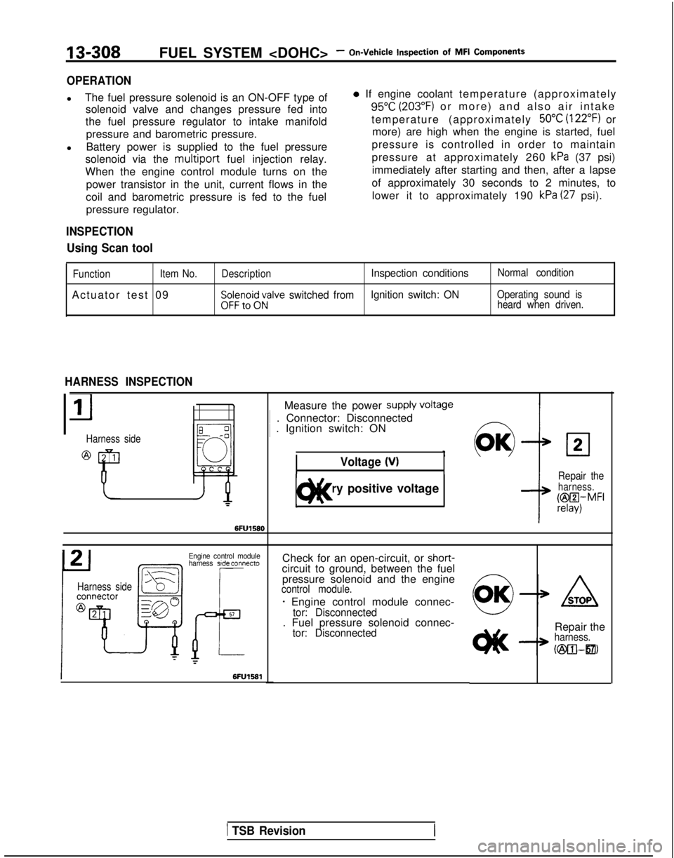
l
The fuel pressure solenoid is an ON-OFF type of
solenoid valve and changes pressure fed into
the fuel pressure regulator to intake manifold
pressure and barometric pressure.
l Battery power is supplied to the fuel pressure
solenoid via the multiport
fuel injection relay.
When the engine control module turns on the
power transistor in the unit, current flows in the
coil and barometric pressure is fed to the fuel pressure regulator.
INSPECTION
Using Scan tool
0 If engine coolant temperature (approximatel
y
95°C (203°F) or more) and also air intake
temperature (approximately
50°C (122°F) or
more) are high when the engine is started, fuel
pressure is controlled in order to maintain
pressure at approximately 260
kPa (37 psi)
immediately after starting and then, after a lapse
of approximately 30 seconds to 2 minutes, to lower it to approximately 190
kPa (27 psi).
Function Item No.
Actuator test 09
DescriptionInspection conditionsNormal condition
$$;;i;;;alve switched fromIgnition switch: ONOperating sound is
heard when driven.
HARNESS INSPECTION
Harness side
Measure the power supply VokW 1
. Connector: Disconnected 1
. Ignition switch: ON
Voltage 04
1 Battery positive voltage 1t)lt<
02
Repair theharness.
@I4,MFI
Engine control module
harness side connecto
Harness side
Check for an open-circuit, or shot-t-circuit to ground, between the fuel
pressure solenoid and the engine
control module.
- Engine control module connec-tor: Disconnected. Fuel pressure solenoid connec-tor: DisconnectedRepair theharness.
h25xwzl21,
1 TSB Revision
Page 452 of 1273
13-310FUEL SYSTEM
of MFI Components
OPERATION
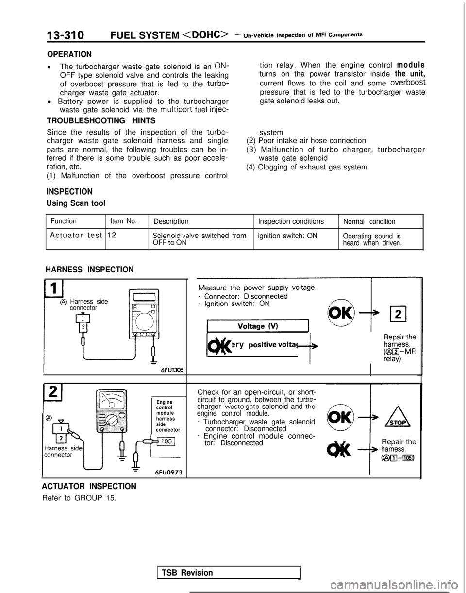
lThe turbocharger waste gate solenoid is an ON-tion relay. When the engine control
module
OFF type solenoid valve and controls the leaking turns on the power transistor inside
the unit,
of overboost pressure that is fed to the
turbo-current flows to the coil and some overboost
charger waste gate actuator. pressure that is fed to the turbocharger waste
l Battery power is supplied to the turbocharger gate solenoid leaks out.
waste gate solenoid via the
multiport fuel injec-
TROUBLESHOOTING HINTS
Since the results of the inspection of the turbo-
charger waste gate solenoid harness and single
parts are normal, the following troubles can be in-
ferred if there is some trouble such as poor accele-
ration, etc.
(1) Malfunction of the overboost pressure control system
(2) Poor intake air hose connection
(3) Malfunction of turbo charger, turbocharger waste gate solenoid
(4) Clogging of exhaust gas system
INSPECTION
Using Scan tool
Function Item No.
Actuator test 12
Description Inspection conditionsNormal condition
Sp:$r?,oi$;;alve switched from
ignition switch: ONOperating sound is
heard when driven.
HARNESS INSPECTION
Harness sideconnector
1
@
uI 6FU1305
Engine
control
module
harness
side
connector
105
JP--r6FUO973
Measure the power supply voltage.
9
1 Battery positivevoltage ]c)ll< f k&f$i
Check for an open-circuit, or short-circuit to around, between the turbn-charger w’aste g&e solenoid and thkengine control module.
* Turbocharger waste gate solenoid
connector: Disconnected
* Engine control module connec-tor: DisconnectedRepair theharness.
C@O--rn)
ACTUATOR INSPECTION
Refer to GROUP 15.
TSB Revision