1989 MITSUBISHI GALANT change time
[x] Cancel search: change timePage 1 of 1273
BACKUP
Service Manual
GRLRNT
1989-1990-1991-1992-1993
Volume 1
Chassis & Mechanical
FOREWORD
This Service Manual has been prepared with thelatest service information available at the time of
publication. It is subdivided into various group cate-
gories and each section contains diagnostic, dis-
assembly, repair, and installation procedures along
with complete specifications and tightening ref-
erences. Use of this manual will aid in properly per-
forming any servicing necessary to maintain or res-
tore the high levels of performance and reliability
designed into these outstanding vehicles.
This BACKUP DSM manual is to be used DNLY as
a SACKUP. please DIJ NOT REDISTRIBUTEWHOLE SECTIONS. This BACKUP was sold to you under the fact that you do indeed
DWNa GENUINE DSM MANUAL. It CANNOT BE considered a REPLACEMENT (Unless your
original
manual was lost or
destroyed.) Please
See
README.TXT
or
README.HTML
for additional
information.
1kyou.
- Gjmpiemym_ay&?h
@
A
.
.”
WE SUPPORT
VOLUNTARY TECHNICIAN
CERTIFICATION THROUGH
Nallonal lnsrltule forAU~~~v3~;VPCT:VE
EXCELLENCE naiLcorn
MITSUBISHIMOTOR SALES OF AMERICA. Inc.
Mltsublshl Motors Corporat!on reserves the right to make changes indesign or to make additions to or Improvements In Its products
wlthout~mposng any obllgatlons upon Itself to install them on its productspreviously manufactured
0 1992 Mitsubishi Motors CorporationRcprintedinUSA
GROUP INDEXMOOAA-
General.........................................................
Engine...........................................................
Fuel................................................................
Cooling.........................................................
Intake and Exhaust..............................
Emission Control....................................
Clutch............................................................
Manual Transaxle..................................
Automatic Transaxle............................
Propeller Shaft........................................
Front Axle..................................................
Rear Axle....................................................
Wheel and Tire.......................................
Power Plant Mount..............................
Front Suspension...................................
Active-Electronic
Control Suspension..............................m
A
Rear Suspension....................................&
Service Brakes.........................................
Parking Brakes........................................
Alphabetical Index.................................
NOTE: Electrical system Information is contained in
Volume 2 “Electrical” of this paired Service Manual.
For overhaul procedures of engines or transmissions,
refer to the separately issued Engine
Service Manual
or Manual/Automatic Transmission Service Manual.
Page 40 of 1273
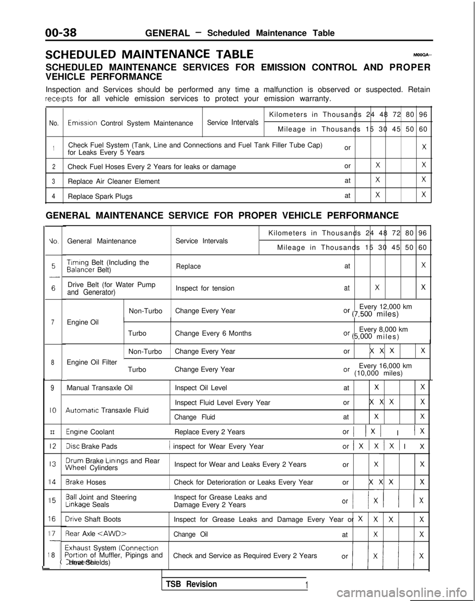
00-38GENERAL- Scheduled Maintenance Table
SCHEDULED MAINTENANCE
TABLEMOOOA-
SCHEDULED MAINTENANCE SERVICES FOR EMISSION CONTROL AND PROPER
VEHICLE PERFORMANCE
Inspection and Services should be performed any time a malfunction is ob\
served or suspected. Retain receipts
for all vehicle emission services to protect your emission warranty.
Kilometers in Thousands 24 48 72 80 96
No.Emwsron Control System MaintenanceService IntervalsMileage in Thousands 15 30 45 50 60
1Check Fuel System (Tank, Line and Connections and Fuel Tank Filler Tube\
Cap) orXfor Leaks Every 5 Years
2Check Fuel Hoses Every 2 Years for leaks or damage orXX
3Replace Air Cleaner ElementatXX
4Replace Spark PlugsatXX
GENERAL MAINTENANCE SERVICE FOR PROPER VEHICLE PERFORMANCE
L
1
1
1
1
1
i
IO.General Maintenance
Service Intervals
7Engine Oil
8
9
IO
III2
I3
14
15
I6
I71
8
L
I
I
I
I
I\
I
II
I
I
;(
Kilometers in Thousands 24 48 72 80 96
Mileage in Thousands 15 30 45 50 60 Timing
Belt (Including the Balancer
Belt)
ReplaceatX
Drive Belt (for Water Pump
Inspect for tensionatXXand Generator)
Non-TurboChange Every Year Every 12,000 kmOr (7,500 miles)
Turbo Change Every 6 Months Every 8,000 km
Or (5.000 miles
)
II
Non-Turbo
Change Every Year or X X XX
Every 16,000 kmOr (10,000 miles)
Engine Oil Filter
TurboChange Every Year
Manual Transaxle Oil 4utomatrc
Transaxle Fluid Inspect Oil Level
at
XX
Inspect Fluid Level Every Yearor X X XX
Change FluidatXX
Engine Coolant
Replace Every 2 YearsOrI 1x1 I IX
Disc Brake Pads1 inspect for Wear Every Yearor/XlXlXl I
X
3rum
Brake Linings
and Rear iNheel
Cylinders Inspect for Wear and Leaks Every 2 Years
or
XX
3rake HosesCheck for Deterioration or Leaks Every Year or X X XX
3all Joint and SteeringInspect for Grease Leaks and-inkage
Seals
Damage Every 2 Years
Or I/ XII x
Irive Shaft Boots Inspect for Grease Leaks and Damage Every Year or XXXX
3ear Axle
Exhaust System (Connectron>ortion of Muffler, Pipings and
Check and Service as Required Every 2 YearsConverter Heat Shields)
TSB Revision1
Page 46 of 1273
GENERAL -Maintenance Service
(1O)Star-t engine and allow to idle for at least two minutes.
Then, with parking brake on, move selector
fever
momentarily to each position, ending in “N” Neutral
position.
(11)Add sufficient ATF to bring fluid level to lower mark.
Recheck fluid level after transaxle is at normal Operating
temperature. Fluid level should be between upper and lower marks of
“HOT” range, Insert dipstick fully to prevent dirt from
entering transaxle.
OOA0051
11 .ENGINE
COOLANT (Change)MOOSEEAC
Check the cooling system parts, such as radiator, heater,
and oil cooler hoses, thermostat and connections for
leakage and damage.
CHANGE COOLANT
1. Remove the radiator cap.
2. Loosen the drain plug to drain the coolant.
3. Drain the coolant from the reserve tank.
4. After draining the coolant, tighten the drain plug securely.
5.Supply the coolant into the radiator until it is filled up to
its filler neck.
6. Supply the coolant into the reserve tank.
7. After warming the engine until the thermostat opens, remove the radiator cap and check the coolant level.
8.Supply the coolant into the radiator until it is filled up to
its filler neck, and install the radiator cap securely.
9.Fill the reserve tank with coolant up to the “FULL” line.
14K512
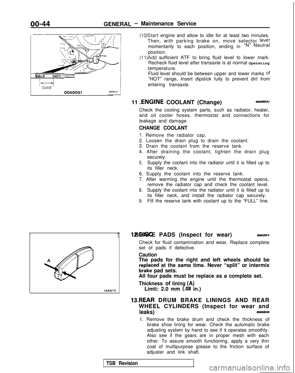
1 12.DISC BRAKE PADS (Inspect for wear) MWSBFA
Check for fluid contamination and wear. Replace complete
set of pads if defective.
Caution
The pads for the right and left wheels should be
reDlaced at the same time. Never “split” or intermix
brkke pad sets.
All four pads must be replace as a complete set.
Thickness of lining (A)
Limit: 2.0 mm (.08 in.)
13.REAR DRUM BRAKE LININGS AND REAR
WHEEL CYLINDERS (Inspect for wear and
leaks)MOOSBGB
1. Remove the brake drum and check the thickness of brake shoe lining for wear. Check the automatic brake
adjusting system by hand to see if it operates smoothly.
Also see if the gears are in proper mesh with each
other. To assure smooth functioning, apply a very thin
coat of multipurpose grease to the friction surface of
adjuster and link shaft.
TSB Revision1
Page 161 of 1273
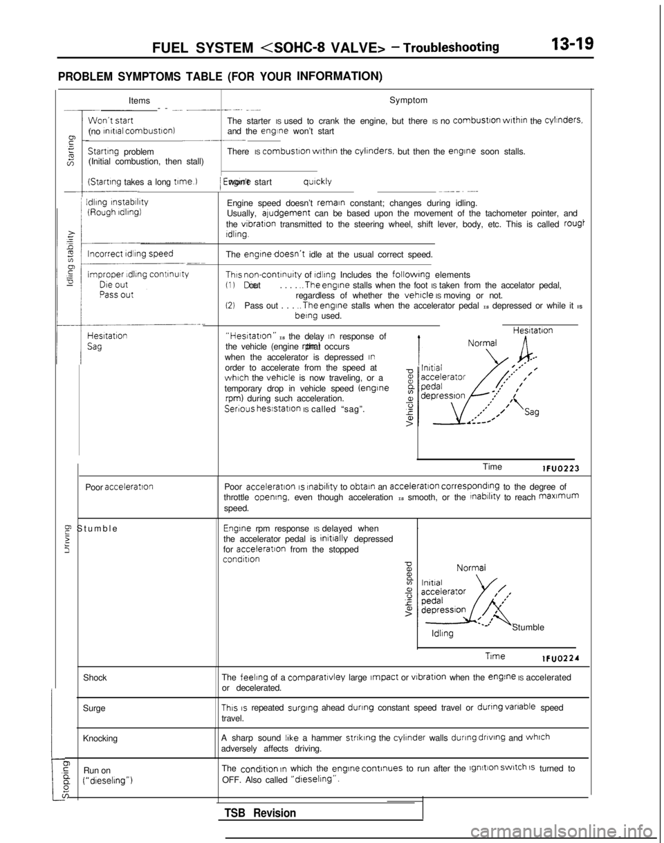
FUEL SYSTEM
PROBLEM SYMPTOMS TABLE (FOR YOURINFORMATION)
:tShock
Surge
Knocking
0,GRun ona (“dieselrng”)
6
Items Symptom
-- -... __----. -~-
The starter IS used to crank the engine, but there IS no
combustron
wrthrn
the cylinders.
(no rnrtral combustron)
and the engine won’t start~-.-__Startrng
problem There IS combustron
wrthrn
the cylrnders.
but then the engrne
soon stalls.
(Initial combustion, then stall)
(Startrng takes a long t1me.l
I
Idling
rnstabrlrty
/ Engrne won’t start qurckly~--_~ -...
Engine speed doesn’t remain constant; changes during idling.
Usually, aludgement can be based upon the movement of the tachometer pointer, and
the
vibration transmitted to the steering wheel, shift lever, body, etc. This is call\
ed rougt
Idling.
The
engtnedoesn’t idle at the usual correct speed.
Thus non-contrnuity of rdlrng Includes the followrng elements(1) Die out
. . . . ..The
engine stalls when the foot IS taken from the accelator pedal,
regardless of whether the vehicle IS moving or not.(2)Pass out . . . ..The
engine stalls when the accelerator pedal IS depressed or while it IS berng
used.
“Hestatton” IS the delay In response of
the vehicle (engine rpm) that occurs
when the accelerator is depressed
Inorder to accelerate from the speed atwhich the vehicle is now traveling, or a
temporary drop in vehicle speed (enginerpm) during such acceleration. Hesltatron
Serious
hesstatlon IS called “sag”.
Poor
acceleration
E Stumbl
e
2
5
Time lFUO223
Poor
acceleration IS rnabilrty
to obtain an acceleration corresponding to the degree of
throttle opening, even though acceleration IS smooth, or the rnabrlrty to reach maxmum
speed.
Engrne rpm response IS delayed when .
the accelerator pedal is initrally
depressed
for acceleratron
from the stopped
condition ldllng
Stumble
Trme lFUO224
The
feeling of a comparatlvley large Impact or vrbration
when the engine IS accelerated
or decelerated.
This IS repeated surging
ahead dunng constant speed travel or dunng
vanable
speed
travel.
A sharp sound
IIke a hammer strtklng the cylinder walls during
dnvtng
and whrch
adversely affects driving.
The
condrtion In which the engrne
continues to run after the lgnltion switch 1s turned to
OFF. Also called
“dreselrng”.
TSB Revision
Page 232 of 1273
13-90 FUEL SYSTEM
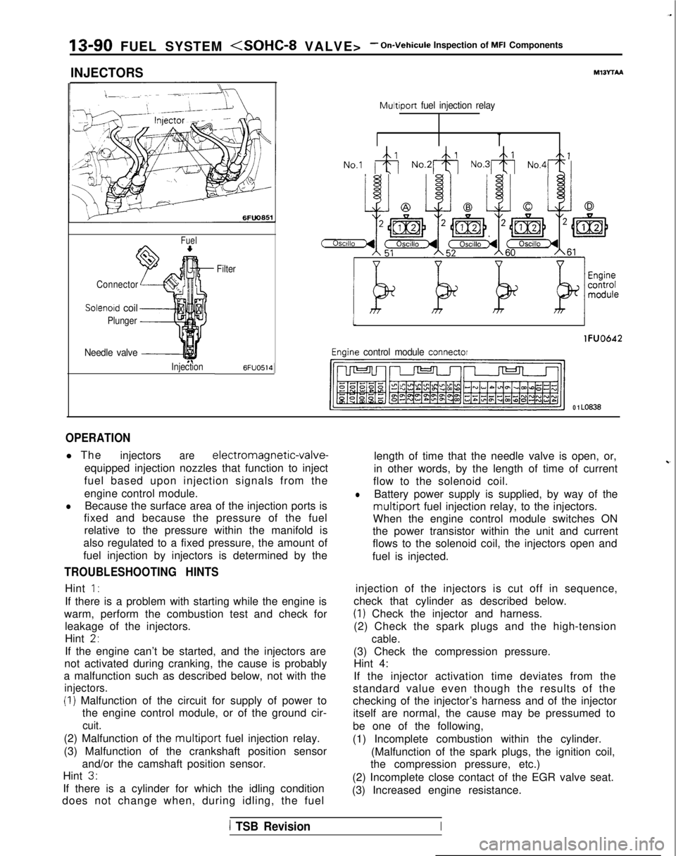
INJECTORS
Fuel
Connector
Solenoid coil
Plunger
Needle valve -----I
InjectionFilter6FUO514
M13rrAA
Multiport
fuel injection relay
No.1 &j No.2& No.3& No,4+
tI
lFUO642
Engine control module connector
CJ=JW=U-I
0 1 LO636
OPERATION
l The
injectorsare electromagnetic-valve-
equipped injection nozzles that function to inject
fuel based upon injection signals from the
engine control module.
lBecause the surface area of the injection ports is
fixed and because the pressure of the fuel
relative to the pressure within the manifold is
also regulated to a fixed pressure, the amount of
fuel injection by injectors is determined by the
TROUBLESHOOTING HINTS
Hint 1:
If there is a problem with starting while the engine is
warm, perform the combustion test and check for leakage of the injectors.
Hint
2,
If the engine can’t be started, and the injectors are
not activated during cranking, the cause is probably
a malfunction such as described below, not with the
injectors.
(I) Malfunction of the circuit for supply of power to the engine control module, or of the ground cir-
cuit.
(2) Malfunction of the multiport fuel injection relay.
(3) Malfunction of the crankshaft position sensor and/or the camshaft position sensor.
Hint
3.
If there is a cylinder for which the idling condition
does not change when, during idling, the fuel length of time that the needle valve is open, or,
in other words, by the length of time of current
~-
flow to the solenoid coil.
lBattery power supply is supplied, by way of the
multiport fuel injection relay, to the injectors.
When the engine control module switches ON
the power transistor within the unit and current
flows to the solenoid coil, the injectors open and
fuel is injected.
injection of the injectors is cut off in sequence,
check that cylinder as described below.
(1) Check the injector and harness.
(2) Check the spark plugs and the high-tension
cable.
(3) Check the compression pressure. Hint 4:
If the injector activation time deviates from the
standard value even though the results of the
checking of the injector’s harness and of the injector itself are normal, the cause may be pressumed to
be one of the following,
(1) Incomplete combustion within the cylinder. (Malfunction of the spark plugs, the ignition coil,
the compression pressure, etc.)
(2) Incomplete close contact of the EGR valve seat.
(3) Increased engine resistance.
1 TSB RevisionI
Page 233 of 1273
FUEL SYSTEM
Inspection of MFI Components13-91
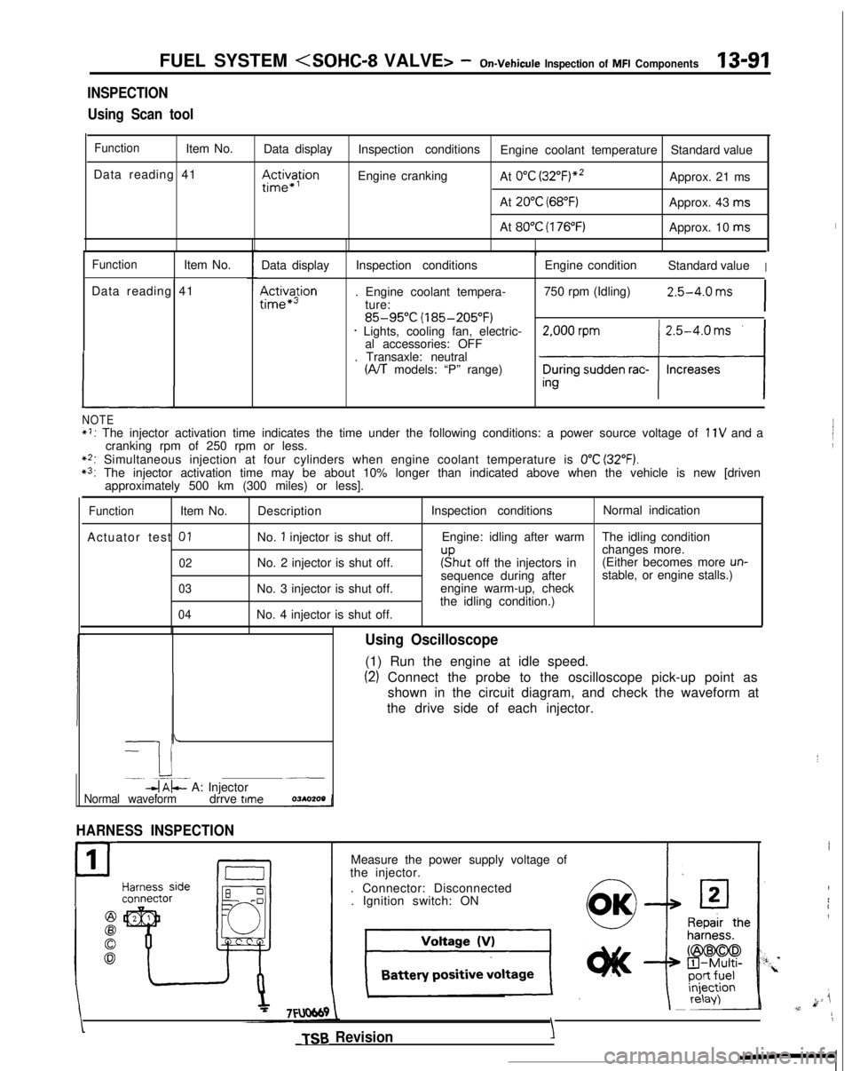
INSPECTION
Using Scan tool
FunctionItem No. Data display
Data reading 41
III~~~ion
Inspection conditions Engine coolant temperature Standard value
Engine cranking At
0°C (3~2°F)“~Approx. 21 ms
At
20°C (68°F)Approx. 43 ms
At
80°C (176°F)Approx. 10 ms
FunctionItem No.
Data reading 41
L
Data display
Ac&a$ion
Inspection conditions
. Engine coolant tempera- ture:
85-95°C (185-205°F)* Lights, cooling fan, electric-al accessories: OFF
. Transaxle: neutral
(A/T models: “P” range) Engine condition
Standard value
I
750 rpm (Idling)2.5-4.0 ms
I
NOTE*I: The injector activation time indicates the time under the following con\
ditions: a power source voltage of 11V and a
cranking rpm of 250 rpm or less.
**: Simultaneous injection at four cylinders when engine coolant temperatur\
e is 0°C (32°F).*3: The injector activation time may be about 10% longer than indicated abo\
ve when the vehicle is new [driven approximately 500 km (300 miles) or less].
FunctionItem No.
Actuator test
01
02
03
04
Description
No.
1 injector is shut off.
No. 2 injector is shut off.
No. 3 injector is shut off.
No. 4 injector is shut off. Inspection conditions
Normal indication
Engine: idling after warm The idling condition
changes more.
r”sput off the injectors in(Either becomes more un-sequence during after stable, or engine stalls.)
engine warm-up, check
the idling condition.)
-
I i-. --.-~-db$- A: Injector~__
Normal waveformdrrve time
HARNESS INSPECTION
1
P
Using Oscilloscope
(1) Run the engine at idle speed.
(2) Connect the probe to the oscilloscope pick-up point as
shown in the circuit diagram, and check the waveform at
the drive side of each injector.
Measure the power supply voltage of
the injector.
. Connector: Disconnected. Ignition switch: ON
TSB Revision
I
I
4
i1
k ji,v,11
\
YIY’.
Page 246 of 1273
13-I 04 FUEL SYSTEM
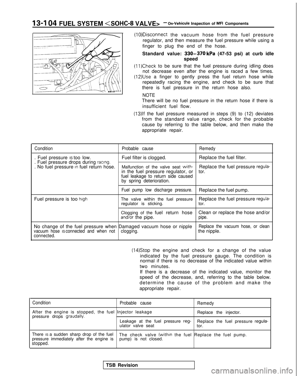
the vacuum hose from the fuel pressure
regulator, and then measure the fuel pressure while using a
finger to plug the end of the hose.
Standard value:
330-370 kPa (47-53 psi) at curb idle
speed
(11)Check to be sure that the fuel pressure during idling does
not decrease even after the engine is raced a few times.
(12)&e a finger to gently press the fuel return hose while
repeatedly racing the engine, and check to be sure that
there is fuel pressure in the return hose also.
NOTE
There will be no fuel pressure in the return hose if there is
insufficient fuel flow.
(13)lf the fuel pressure measured in steps (9) to (12) deviates
from the standard value range, check for the probable
cause by referring to the table below, and then make the
appropriate repair.
Condition Probable causeRemedy
. Fuel pressure IS too low. Fuel filter is clogged.Replace the fuel filter.
. Fuel pressure drops during racing.. No fuel pressure In fuel return hose. Malfunction of the valve seat with-Replace the fuel pressure regula-in the fuel pressure regulator, ortor.
fuel leakage to return side caused by spring deterioration.
Fuel pump low discharge pressure.Replace the fuel pump.
Fuel pressure is too
highThe valve within the fuel pressure Replace the fuel pressure regula-regulator is sticking.
tor.
Clogging of the fuel return hose Clean or replace the hose and/or
and/or the pipe.pipe.
No change of the fuel pressure when Damaged vacuum hose or nippleReplace the vacuum hose, or clean
vacuum hose IS connected and when not clogging.the nipple.connected.
(14)Stop the engine and check for a change of the value
indicated by the fuel pressure gauge. The condition is
normal if there is no decrease of the indicated value within
two minutes. If there is a decrease of the indicated value, monitor the
speed of the decrease, and, referring to the table below.
determine the cause of the problem and make the
appropriate repair.
Condition Probable cause
After the engine is stopped, the fuel Injector leakage
pressure drops graudally.
Remedy
Replace the injector.
Leakage at the fuel pressure reg-
Replace the fuel pressure regula-
ulator valve seat tor.
There IS a sudden sharp drop of the fuel The check valve
(within the fuel Replace the fuel pump.
pressure immediately after the engine is pump) is not closed.
stopped.
TSB Revision
Page 324 of 1273
13-182FUEL SYSTEM
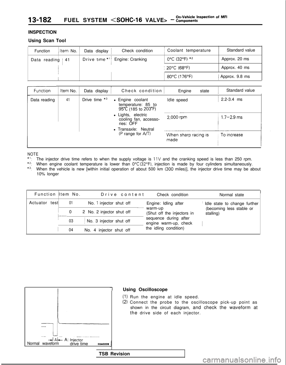
INSPECTION
Using Scan Tool
Function1 Item
No. ’Data display 1Check conditionI Coolant temperature Standard value
IData reading / 41Drive trme
*’ 1Engine: Cranking0°C (32°F) *2Approx. 20 ms
j: 20°C (68°F)Approx. 40 ms 80°C
(176°F)/ Approx. 9.8 ms
Data reading
NOTE Item
No.
41 i
Data display 1
Check condition
IEngine state 1Standard value
Drive time
*3l Engine coolant temperature: 85 to
95°C (185 to 203°F)
l Lights, electric cooling fan, accesso-ries: OFF
l Transaxle: Neutral
(P range for AIT) Idle
speed
1 2.2-3.4 ms
*‘:The injector drive time refers to when the supply voltage is 11 V and the cranking speed is less than 250 rpm.
*2:When engine coolant temperature is lower than 0°C (32°F). injection is made by four cylinders simultaneously.
*3:When the vehicle is new [within initial operation of about 500 km (300 miles)], the injector drive time may be about
10% longer
Function Item No
.
Drive content Check condition Normal state
Actuator test
01No. 1 injector shut off Engine: Idling afterI Idle state to change further
0
2
No. 2 injector shut off
- warm-up
(becoming less stable or
(Shut off the injectors in stalling)
03li No. 3 injector shut off sequence during after-engine warm-up, check1
I04No. 4 injector shut off
the idling condition)
-k
Imp
4 AL A: Inje,t,r--m--m-Normal waveformdrive time03*0209
(1) Run the engine at idle speed.
(2) Connect the probe to the oscilloscope pick-up point as
shown in the circuit diagram, and check the waveform at
the drive side of each injector.
1
TSB Revision 1
Using Oscilloscope