1989 MITSUBISHI GALANT automatic
[x] Cancel search: automaticPage 1 of 1273
BACKUP
Service Manual
GRLRNT
1989-1990-1991-1992-1993
Volume 1
Chassis & Mechanical
FOREWORD
This Service Manual has been prepared with thelatest service information available at the time of
publication. It is subdivided into various group cate-
gories and each section contains diagnostic, dis-
assembly, repair, and installation procedures along
with complete specifications and tightening ref-
erences. Use of this manual will aid in properly per-
forming any servicing necessary to maintain or res-
tore the high levels of performance and reliability
designed into these outstanding vehicles.
This BACKUP DSM manual is to be used DNLY as
a SACKUP. please DIJ NOT REDISTRIBUTEWHOLE SECTIONS. This BACKUP was sold to you under the fact that you do indeed
DWNa GENUINE DSM MANUAL. It CANNOT BE considered a REPLACEMENT (Unless your
original
manual was lost or
destroyed.) Please
See
README.TXT
or
README.HTML
for additional
information.
1kyou.
- Gjmpiemym_ay&?h
@
A
.
.”
WE SUPPORT
VOLUNTARY TECHNICIAN
CERTIFICATION THROUGH
Nallonal lnsrltule forAU~~~v3~;VPCT:VE
EXCELLENCE naiLcorn
MITSUBISHIMOTOR SALES OF AMERICA. Inc.
Mltsublshl Motors Corporat!on reserves the right to make changes indesign or to make additions to or Improvements In Its products
wlthout~mposng any obllgatlons upon Itself to install them on its productspreviously manufactured
0 1992 Mitsubishi Motors CorporationRcprintedinUSA
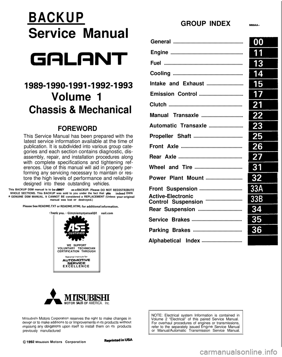
GROUP INDEXMOOAA-
General.........................................................
Engine...........................................................
Fuel................................................................
Cooling.........................................................
Intake and Exhaust..............................
Emission Control....................................
Clutch............................................................
Manual Transaxle..................................
Automatic Transaxle............................
Propeller Shaft........................................
Front Axle..................................................
Rear Axle....................................................
Wheel and Tire.......................................
Power Plant Mount..............................
Front Suspension...................................
Active-Electronic
Control Suspension..............................m
A
Rear Suspension....................................&
Service Brakes.........................................
Parking Brakes........................................
Alphabetical Index.................................
NOTE: Electrical system Information is contained in
Volume 2 “Electrical” of this paired Service Manual.
For overhaul procedures of engines or transmissions,
refer to the separately issued Engine
Service Manual
or Manual/Automatic Transmission Service Manual.
Page 3 of 1273
00-l
GENERAL
CONTENTS
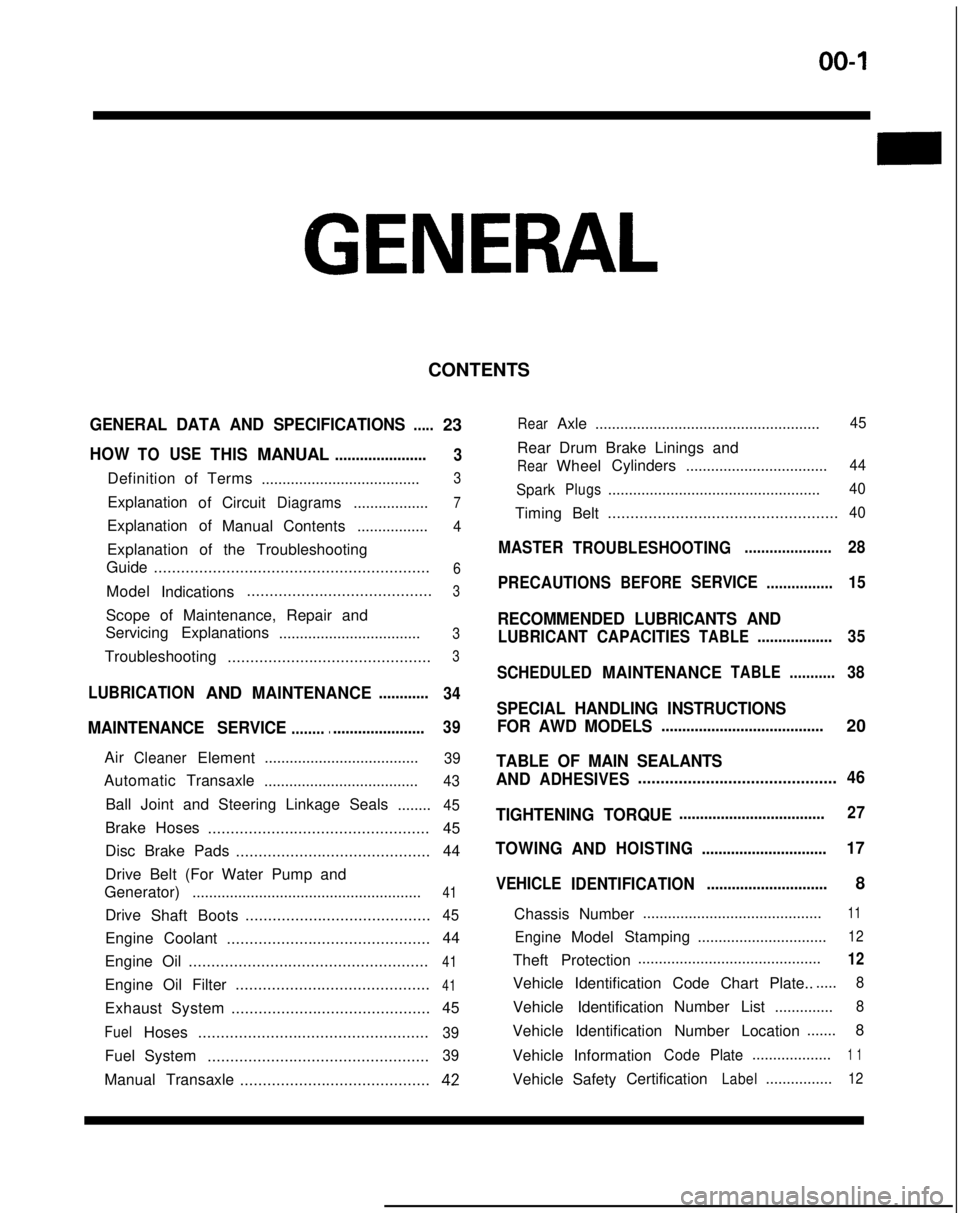
GENERAL DATA AND SPECIFICATIONS.....23
HOWTOUSETHISMANUAL......................
3
Definition of Terms ......................................3
ExplanationofCircuitDiagrams..................7
Explanation of
ManualContents .................4
Explanation of the Troubleshooting
Guide .............................................................
6
Model
Indications .........................................3
Scope of Maintenance, Repair and
Servicing Explanations
..................................
3
Troubleshooting .............................................3
LUBRICATIONANDMAINTENANCE............
34
MAINTENANCE SERVICE............................... 39
AirCleanerElement
.....................................39
Automatic
Transaxle
.....................................43
Ball Joint and Steering Linkage Seals ........45
Brake Hoses................................................. 45
Disc Brake Pads ........................................... 44
Drive Belt (For Water Pump and
Generator) .......................................................
41
Drive
Shaft Boots .........................................45
Engine Coolant
............................................. 44
Engine Oil .....................................................
41
Engine Oil Filter ...........................................41
Exhaust System
............................................ 45
FuelHoses
...................................................39
Fuel System
.................................................39
Manual Transaxle ..........................................42
RearAxle......................................................45
Rear Drum Brake Linings and
RearWheel Cylinders
..................................44
Spark
Plugs...................................................40
Timing Belt...................................................40
MASTER
TROUBLESHOOTING.....................28
PRECAUTIONS
BEFORESERVICE................15
RECOMMENDED LUBRICANTS AND
LUBRICANT CAPACITIESTABLE..................35
SCHEDULED
MAINTENANCETABLE ...........38
SPECIAL HANDLING INSTRUCTIONS
FOR AWD MODELS
.......................................20
TABLE OF MAIN SEALANTS
AND
ADHESIVES ............................................46
TIGHTENING TORQUE
................................... 27
TOWING
ANDHOISTING ..............................17
VEHICLE
IDENTIFICATION .............................8
Chassis Number ...........................................
11
EngineModel
Stamping
...............................12
Theft Protection ............................................12
Vehicle Identification Code Chart Plate.......
8
Vehicle Identification Number List
..............8
Vehicle Identification Number Location .......
8
Vehicle Information
CodePlate...................1 1
Vehicle SafetyCertificationLabel................12
Page 5 of 1273
GENERAL - How to Use This Manual00-3
HOW
TO USE THIS MANUALMOOBMTO
SCOPE OF MAINTENANCE, REPAIR AND
DEFINITION OF TERMS
SERVICING EXPLANATIONS STANDARD VALUE
This manual provides explanations, etc. concerning procedures for the inspection, maintenance, repair
and servicing of the subject model. Unless other-
wise specified, each service procedure covers all models. Procedures covering specific models are
identified by the model codes, or similar designation
(engine type, transaxle type, etc.). A description of
these designations is covered in this unit under “VEHICLE IDENTIFICATION”.
SERVICE ADJUSTMENT PROCEDURES
“Service Adjustment Procedures” are procedures
for performing inspections and adjustments of
particularly important locations with regard to the
construction and for maintenance and servicing, but
other inspections (for looseness, play, cracking,
damage, etc.) must also be performed.
SERVICE PROCEDURES
The service steps are arranged in numerical order and attentions to be paid in performing vehicleservice are described in detail in SERVICE POINTS.
TROUBLESHOOTING
Troubleshootinqs are classified into master trou-
bleshooting and group troubleshooting and located
as follows:
The master troubleshooting is prepared when the trouble symptom relates to two or more groups and
given in MASTER TROUBLESHOOTING.
The group troubleshooting guide is prepared for causes of problems related to that individual group
only; a troubleshooting guide is prepared for each
appropriate group. Indicates the value used as the standard for judging
the quality of a part or assembly on inspectian or the
value to which the part or assembly is corrected and
adjusted. It is given by tolerance.
LIMIT
Shows the standard for judging the quality of a part
or assembly on inspection and means the maximum
or minimum value within which the part or assembly must be kept functionally or in strength. It is a value
established outside the range of standard value.
REFERENCE VALUE
Indicates the adjustment value prior to starting the
work (presented in order to facilitate assembly and adjustment procedures, and so they can be
com- pleted
in a shorter time).
CAUTION
Indicates the presentation of information particularly
vital to the worker during the performance of maintenance and servicing procedures in order to
avoid the possibility of injury to the worker; or
damage to component parts, or a reduction of
component or vehicle function or performance, etc.
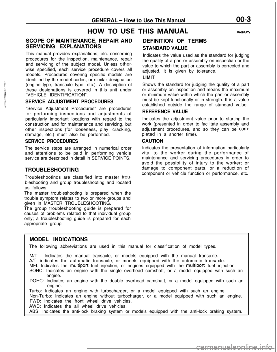
MODEL INDICATIONS
The following abbreviations are used in this manual for classification o\
f model types.
M/T . Indicates the manual transaxle, or models equipped with the manual\
transaxle.
A/T: indicates the automatic transaxle, or models equipped with the automati\
c transaxle.
MFI: Indicates the multiport
fuel injection, or engines equipped with the
multiport fuel injection.
SOHC: Indicates an engine with the single overhead camshaft, or a model \
equipped with such an engine.
DOHC: Indicates an engine with the double overhead camshaft, or a model \
equipped with such an engine.
Turbo: Indicates an engine with turbocharger, or a model equipped with s\
uch an engine. Non-Turbo: Indicates an engine without turbocharger, or a model equipped\
with such an engine.FWD: Indicates the front wheel drive vehicles.
AWD: Indicates the all wheel drive vehicles. ABS: Indicates the anti-lock braking system or models equipped with the \
anti-lock braking system.
Page 6 of 1273
00-4GENERAL - How to Use This Manual
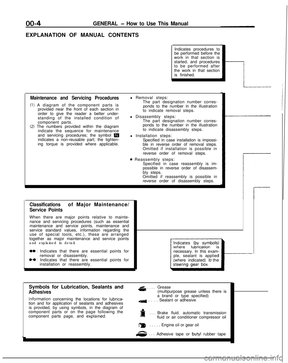
EXPLANATION OF MANUAL CONTENTSIndicates procedures to
be performed before the
work in that section is
started, and procedures
to be performed after
the work in that section
is finished.
Maintenance and Servicing Procedures
(1) A diagram of the component parts is provided near the front of each section in
order to give the reader a better under-
standing of the installed condition of
component parts.
(2) The numbers provided within the diagram indicate the sequence for maintenance
and servicing procedures; the symbol
mindicates a non-reusable part; the tighten-
ing torque is provided where applicable. l Removal steps:
The part designation number corres-
ponds to the number in the illustration
to indicate removal steps.
l Disassembly steps: The part designation number corres-
ponds to the number in the illustration
to indicate disassembly steps.
l Installation steps: Specified in case installation is impossi-
ble in reverse order of removal steps.
Omitted if installation is possible in
reverse order of removal steps.
8 Reassembly steps: Specified in case reassembly is im-
possible in reverse order of disassem-
bly steps.
Omitted if reassembly is possible in reverse order of disassembly steps.
Classificationsof Major Maintenance/
Service Points
When there are major points relative to mainte-
nance and servicing procedures (such as essential
maintenance and service points, maintenance and
service standard values, information regarding the
use of special tools, etc.), these are arranged
together as major maintenance and service points
and explained in detail.
*+ : Indicates that there are essential points for
removal or disassembly.
I)+ : Indicates that there are essential points forinstallation or reassembly. necessary. In this exam-
ple, sealant is applied
(where indicated) to the
I---
Symbols for Lubrication, Sealants and
Adhesives
4 . . . . .Grease
(multipurpose grease unless there is Information
concerning the locations for lubrica-
tion and for application of sealants and adhesives
is provided, by using symbols, in the diagram of
component parts or on the page following the
component parts page, and explarned.
a brand or type specified)
4 . . . . Sealant or adhesive
a. . . . .Brake fluid. automatic transmission
fluid or air conditioner compressor oil
a. . . . . Engine oil or gear oil
. . .Adhesive tape or butyl
rubber tape
Page 15 of 1273
GENERAL - Vehicle Identification00-13
LOCATIONS
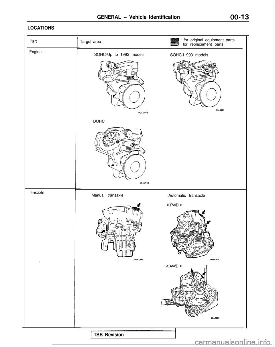
Part
Engine
*ansaxle
.
Target area: for original equipment partsLZZB : for replacement parts
SOHC-Up to 1992 models SOHC-l 993 models
DOHC
Manual transaxle Automatic transaxle
1 TSB Revision
Page 19 of 1273
GENERAL - Towina and Hoisting
00-l 7
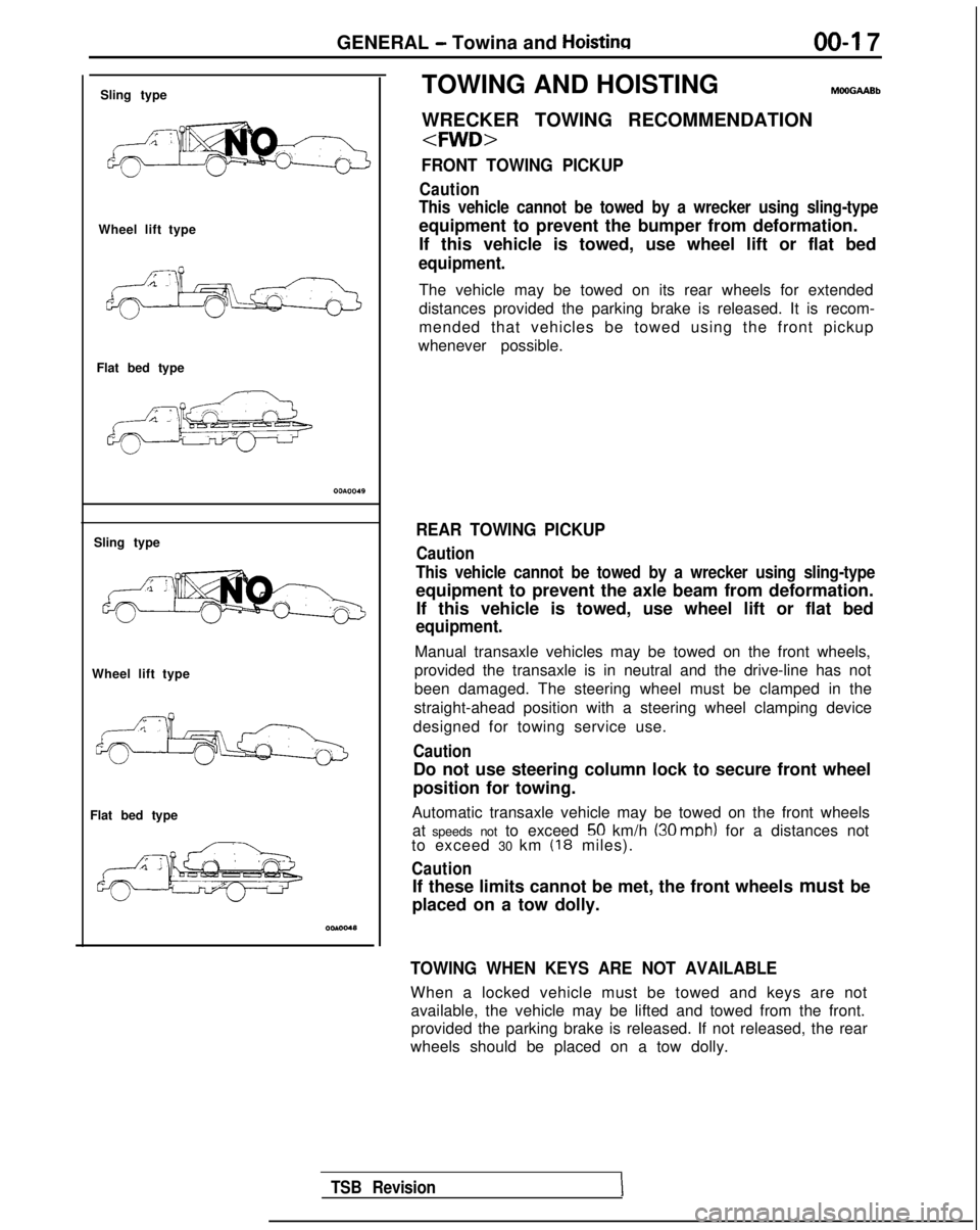
Sling type
Wheel lift type
Flat bed type
Sling type
Wheel lift type
Flat bed type TOWING AND HOISTING
WRECKER TOWING RECOMMENDATION
FRONT TOWING PICKUP
Caution
This vehicle cannot be towed by a wrecker using sling-type
equipment to prevent the bumper from deformation.
If this vehicle is towed, use wheel lift or flat bed
equipment.
The vehicle may be towed on its rear wheels for extended
distances provided the parking brake is released. It is recom-
mended that vehicles be towed using the front pickup
whenever possible.
REAR TOWING PICKUP
Caution
This vehicle cannot be towed by a wrecker using sling-type
equipment to prevent the axle beam from deformation. If this vehicle is towed, use wheel lift or flat bed
equipment.
Manual transaxle vehicles may be towed on the front wheels,
provided the transaxle is in neutral and the drive-line has not
been damaged. The steering wheel must be clamped in the
straight-ahead position with a steering wheel clamping device
designed for towing service use.
Caution
Do not use steering column lock to secure front wheel
position for towing.
Automatic transaxle vehicle may be towed on the front wheels at speeds not to exceed
50 km/h (30 mob) for a distances not
to exceed 30 km (18 miles).
Caution
If these limits cannot be met, the front wheels must be
placed on a tow dolly.
TOWING WHEN KEYS ARE NOT AVAILABLE
When a locked vehicle must be towed and keys are not available, the vehicle may be lifted and towed from the front.provided the parking brake is released. If not released, the rear
wheels should be placed on a tow dolly.
TSB Revision
Page 26 of 1273
00-24GENERAL - General Data and Specifications
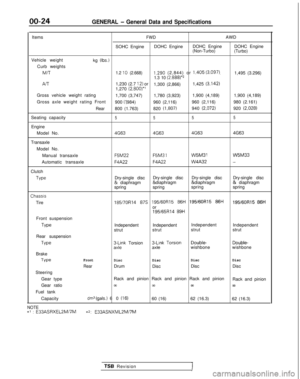
ItemsFWDAWD
SOHC Engine DOHC Engine DOHC Engine DOHC Engine
(Non-Turbo)
(Turbo)
Vehicle weight
kg (Ibs.)
Curb weightsMIT
1.2 10 (2.668)1.290 (2,844) or 1.405 (3.097).1,495 (3.296)1.3 10 (2.8881e2
/-v-r1,230 (2.7 12) or
1,300 (2,866) 1,425 (3.142)
1,270
(2.800)”
Gross vehicle weight rating 1,700 (3,747) 1,780 (3,923)1,900 (4,189)
1,900 (4,189)
Gross axle weight rating Front 900 (I ,984)
960 (2,116) 960 (2,116)
980 (2.161)
Rear800 (1.763)820 (1,807)940 (2.072)920 (2.028)
Seating capacity5 55 5
Engine
Model No.
4G634G63 4G634G63
Transaxle
Model No.Manual transaxle F5M22 F5M3
1 W5M31 W5M33
Automatic transaxle
F4A22F4A22 W4A32-
Clutch
Type
Dry-single disc
Dry-single disc
Dry-single disc Dry-single disc &
diaphragm & diaphragm & diaphragm &
diaphragm
spring spring spring
springChassis
Tire
185/7OR14 87s 195/60R15 86i-i 195/60R15 86ti195/60R15 86H
or
195/65R14 89H
Front suspension Type
Independent Independent
Independent
Independent
strut strut strut
strut
Rear suspension Type
3L$k Torsion3$k Torsion Double-
Double-
wishbone wishbone
Brake Type
Front
DiscDisc Disc
Disc
RearDrum
Disc Disc
Disc
Steering
Gear type Rack and pinion Rack and pinion Rack and pinion
Rack and pinion
Gear ratio
cc00m03
Fuel tank
Capacity
dm3(gals.) 60 (16)60 (16) 62 (16.3)
62 (16.3)
NOTE+’ : E33ASRXEL2Mi7M~2:
E33ASNXML2Mi7M
TSB RevisionI
Page 27 of 1273
GENERAL - General Data and Specifications00-25
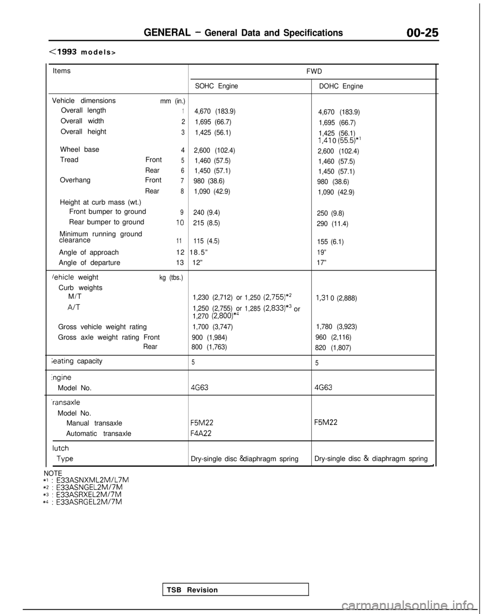
(1993 models
>
Items
FWD
SOHC Engine DOHC Engine
Vehicle dimensionsmm (in.)
Overall length14,670 (183.9)
4,670 (183.9)
Overall width21,695 (66.7)1,695 (66.7)
Overall height31,425 (56.1)1,425 (56.1) I,41
0
(55.5)*’
Wheel base4
2,600 (102.4)
2,600 (102.4)
Tread Front51,460 (57.5)1,460 (57.5)
Rear
61,450 (57.1) 1,450 (57.1)
Overhang Front7980 (38.6)980 (38.6)
Rear
81,090 (42.9) 1,090 (42.9)
Height at curb mass (wt.)
Front bumper to ground
9240 (9.4) 250 (9.8)
Rear bumper to ground10215 (8.5)290 (11.4)
Minimum running ground
clearance11115 (4.5)155 (6.1)
Angle of approach 12 18.5”19”
Angle of departure13 12”17”
lehicle weightkg (tbs.)
Curb weights
M/T
1,230 (2,712) or1,250 (2,755)*’I,31
0 (2,888)
A/T1,250 (2,755) or1,285(2,833)*3or1,270 (2,800)*4
Gross vehicle weight rating1,700 (3,747) 1,780 (3,923)
Gross axle weight rating Front900 (1,984)960 (2,116)
Rear 800 (1,763)
820 (1,807)
ieating capacity55lngine
Model No.
4G634G63 -ransaxle
Model No. Manual transaxle
F5M22 F5M22
Automatic transaxle
F4A22 lutch
Type
Dry-single disc & diaphragm spring
Dry-single disc &
diaphragm spring
d
TSB Revision
NOTE*l : E33ASNXML2MlL7M*2 : E33ASNGEL2MI7M*3 :
E33ASRXEL2M/7M*4 :
E33ASRGEL2M/7M