Page 32 of 1273

00-30GENERAL - Master Troubleshooting
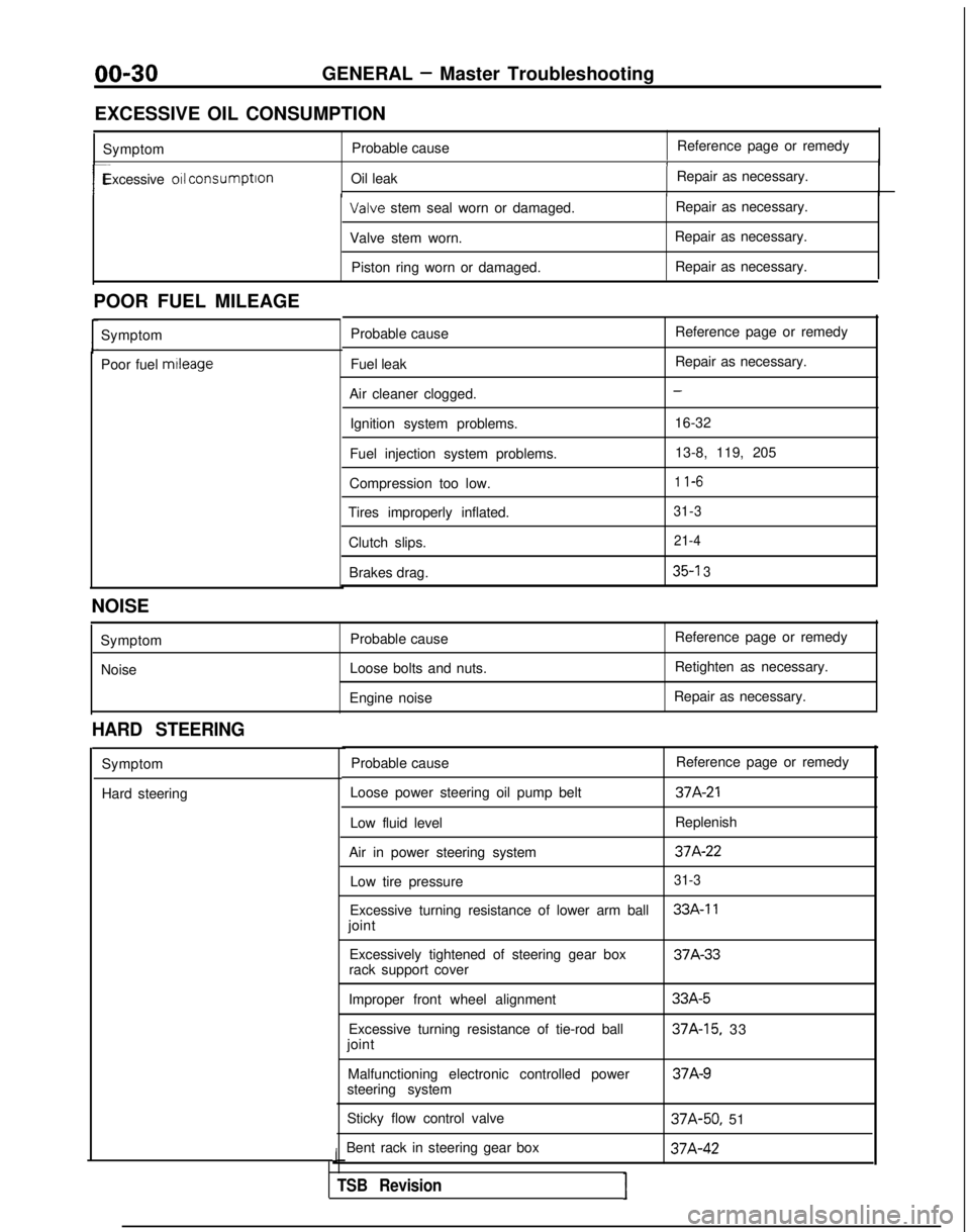
EXCESSIVE OIL CONSUMPTION Symptom Probable cause Reference page or remedy
1
r-Excessive 011 consumption
Oil leak Repair as necessary.I Valve
stem seal worn or damaged. Repair as necessary.
Valve stem worn. Repair as necessary.
Piston ring worn or damaged. Repair as necessary.
POOR FUEL MILEAGE Symptom
Poor fuel mtleage
Probable cause
Fuel leak
Air cleaner clogged. Ignition system problems.
Fuel injection system problems.
Compression too low.
Tires improperly inflated.
Clutch slips.Brakes drag. Reference page or remedy
Repair as necessary.
-
16-32
13-8, 119, 205
1 l-6
31-3 21-4
35-l 3
NOISE
SymptomNoise Probable cause
Loose bolts and nuts.
Engine noise Reference page or remedy
Retighten as necessary.
Repair as necessary.
HARD STEERING
Symptom
Hard steering Probable cause
Reference page or remedy
Loose power steering oil pump belt
37A-21
Low fluid level Replenish
Air in power steering system
37A-22
Low tire pressure31-3
Excessive turning resistance of lower arm ball33A-11
joint Excessively tightened of steering gear box 37A-33
rack support cover
Improper front wheel alignment
Excessive turning resistance of tie-rod ball
joint
Malfunctioning electronic controlled power
steering system
Sticky flow control valve
Bent rack in steering gear box
J
TSB RevisionI
33A-5
37A-15, 33 37A-9
37A-50,
51 37A-42
Page 50 of 1273
00-48GENERAL - Table of Main Sealants and Adhesives
Application
Recommended brand
(4) Sealant for drum brake shoe hold-down pin, wheel 3M
ATD Part No.8513
or equivalent
cylinder
7. Instant super-strong adhesive l Gluing of all kinds of material 3M
ATD Part No.8155
or equivalent
plyethylene, polypropylene,
fluororesin and other surface absorbent materials>
3. Anaerobic super-strong adhesive
(I) Fixing of screws, bolts, etc. 3M
Stud locking Part No.4170
or equivalent
l Tightening parts for drive gear and differential case
l Tilt steering upper, lower column joint bolt
(2) Fixing of joints of bearings, fan, pulley, gear, etc.
(3) Sealing of small gaps and flange surface
(4) Steering angle 3M
Nut locking Part
No.4171 or equivalent
stopper bolt (Jeep)
3. Undercoating 3M
ATD Part No.8864
or equivalent
1 TSB Revision
Page 871 of 1273

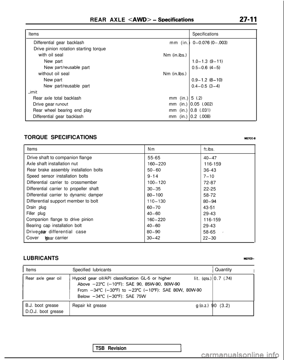
REAR AXLE - SDecifications27-11
Items
Differential gear backlash
Drive pinion rotation starting torque
with oil seal
New part
New part/reusable part
without oil seal New part
New part/reusable part -imit
Rear axle total backlash
Drive gear runout
Rear wheel bearing end play
Differential gear backlash
Specifications
mm (in.) O-0.076 (O-.003)
Nm (in.lbs.) 1.0-1.3
(9-11)
0.5-0.6
(4-5)
Nm
(in.lbs.1 0.9-1.2
(8-10)
0.4-0.5
(3-4)
mm (in.) 5
(2)
mm (in.) 0.05 (.002)
mm (in.) 0.8 (.031)
mm (in.) 0.2 (008)
TORQUE SPECIFICATIONSM27cc-B
ItemsNmft.lbs.
Drive shaft to companion flange 55-6540-47
Axle shaft installation nut 160-220
116-159
Rear brake assembly installation bolts50-6036-43
Speed sensor installation bolts9-1
4
7-10
Differential carrier to crossmember
100-120
72-87
Differential carrier to propeller shaft30-3522-25
Differential carrier to dynamic damper80- 10058-72
Differential support member to bolt 110-130
80-94
Drain plug60-7043-51
Filler plug40-6029-43
Companion flange to drive pinion
160-220
116-159
Bearing cap installation bolt40-6029-43
Drive to differential case
gear80-9058-651
Cover to carriergear30-4222-30
TSB Revision
LUBRICANTS
IItemsSpecified lubricants1 QuantityI
lit. (qts.) 0.7 (74)
B.J. boot grease Repair kit grease
g (oz.) 90 (3.2)
D.O.J. boot grease
Page 913 of 1273

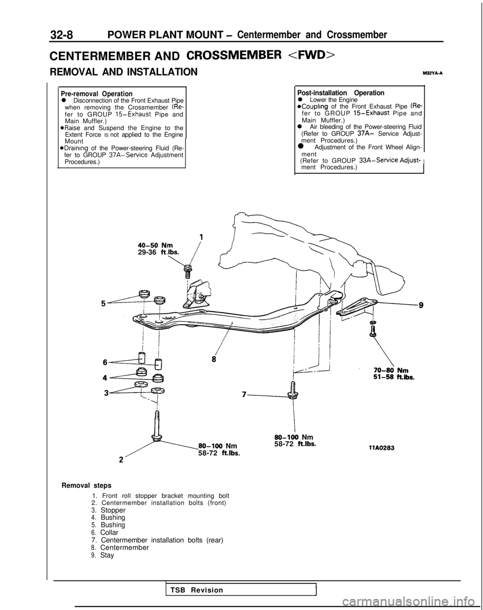
32-8POWER PLANT MOUNT -Centermember and Crossmember
CENTERMEMBER ANDCROSSMEMBER
REMOVAL AND INSTALLATIONM3ZYA-A
Pre-removal Operationl Disconnection of the Front Exhaust Pipe
when removing the Crossmember (Re-fer to GROUP 15-Exhaust Pipe and
Main Muffler.) aRaise
and Suspend the Engine to the
Extent Force IS not applied to the Engine
Mount
@Draining of the Power-steering Fluid (Re-
fer to GROUP 37A-Service Adjustment
Procedures.)
40-50 N29-36 ft
Post-installation Operationl Lower the Engine*Coupling of the Front Exhaust Pipe (Re-fer to GROUP 15-Exhaust Pipe and
Main Muffler.)
l Air bleeding of the Power-steering Fluid
(Refer to GROUP
37A- Service Adjust-
ment Procedures.)
l Adjustment of the Front Wheel Align-
ment
(Refer to GROUP
33A-Service Adjust-Iment Procedures.)
80-100 Nm
58-72 ft.lbs.
80-100 Nm
58-72 ft.lbs.
Removal steps
1. Front roll stopper bracket mounting bolt
2. Centermember installation bolts (front)
3.Stopper4.Bushing5.Bushing6.Collar
7. Centermember installation bolts (rear)
8.Centermember9.Stay llA0283
TSB Revision
Page 1086 of 1273
REAR SUSPENSION - Troubleshooting/Service Adjustment Procedures34-5
TROUBLESHOOTING
M34EAA
Symptom Probable cause( Remedy
Squeaks or other
abnormal noise Loose rear suspension installation bolts and nuts
Retighten
IMalfunction of shock absorber
Worn bushingsReplace
Poor ride
Excessive tire inflation pressureIAdjust the pressure
Malfunction of shock absorber
Weak or broken springs
Replace
Body tilting Weak or deteriorated bushings
Weak or broken springsReplace
TSB Revision
SERVICE ADJUSTMENT PROCEDUEZ$
REAR WHEEL ALIGNMENT INSPECTION
The rear suspension assembly must be free of worn, loosen or
damaged parts prior to measurement of rear wheel alignment.
Standard value: Toe-in (Left-right difference)
0+3 mm (Ok.118
in.)
Camber-45’ f 30’
NOTE
The rear wheel alignment is set at the factory and cannot be
adjusted. If toe-in or camber is not within the standard value, replace
bent or damaged parts.
Page 1104 of 1273

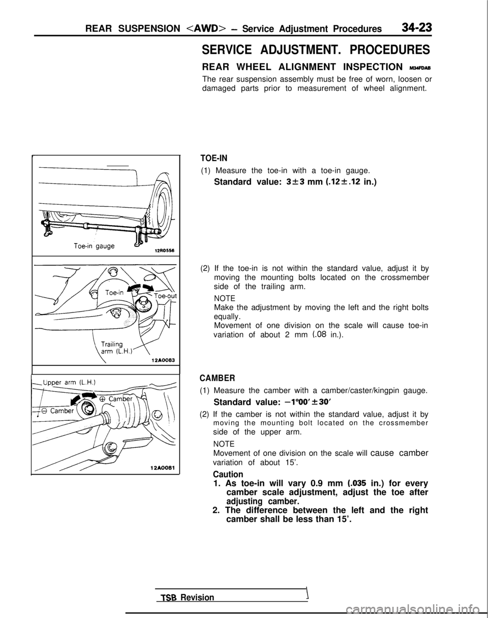
REAR SUSPENSION - Service Adjustment Procedures34-23
12AOO83
12A0081
SERVICE ADJUSTMENT. PROCEDURES
REAR WHEEL ALIGNMENT INSPECTION mm
The rear suspension assembly must be free of worn, loosen or
damaged parts prior to measurement of wheel alignment.
TOE-IN
(1) Measure the toe-in with a toe-in gauge.
Standard value:
3+3 mm (.12+.12 in.)
(2) If the toe-in is not within the standard value, adjust it by moving the mounting bolts located on the crossmember
side of the trailing arm.
NOTE
Make the adjustment by moving the left and the right bolts
equally.
Movement of one division on the scale will cause toe-in
variation of about 2 mm
(.08 in.).
CAMBER
(1) Measure the camber with a camber/caster/kingpin gauge.
Standard value:
-1”OO’f30’
(2) If the camber is not within the standard value, adjust it bymoving the mounting bolt located on the crossmember
side of the upper arm.
NOTE
Movement of one division on the scale will cause camber
variation of about 15’.
Caution
1. As toe-in will vary 0.9 mm LO35 in.) for every
camber scale adjustment, adjust the toe after
adjusting camber.
2. The difference between the left and the right camber shall be less than 15’.
TSB Revision \
Page 1128 of 1273
![MITSUBISHI GALANT 1989 Service Repair Manual SERVICE BRAKES - Specifications357
SERVICE SPECIFICATIONS [Up to 1990.5 models]
ItemsFWDAWD
Standard value Brake pedal height mm (in.) 176-181 (6.9-7.1)176-181
(6.9-7.1)
Brake pedal free play
mm (in. MITSUBISHI GALANT 1989 Service Repair Manual SERVICE BRAKES - Specifications357
SERVICE SPECIFICATIONS [Up to 1990.5 models]
ItemsFWDAWD
Standard value Brake pedal height mm (in.) 176-181 (6.9-7.1)176-181
(6.9-7.1)
Brake pedal free play
mm (in.](/manual-img/19/57312/w960_57312-1127.png)
SERVICE BRAKES - Specifications357
SERVICE SPECIFICATIONS [Up to 1990.5 models]
ItemsFWDAWD
Standard value Brake pedal height mm (in.) 176-181 (6.9-7.1)176-181
(6.9-7.1)
Brake pedal free play
mm (in.) 3-8 (.I-.3)3-8 (.l-.3)
Brake pedal to floorboard clearancemm (in.) 80 (3.1) or more80 (3.1) or more
Proportioning valve pressure MPa (psi)
Split point 3.95-4.45 (561-633)
i.95-5.45 (704-775)
Output pressure [input pressure]
5.15-5.65 (732-804)*’ 6.55-7.05 (931-1,003)5.55-6.05 (789-861)“’ [9.2 (1.309)][8.2 (1,163)l
Booster push rod to master cylinder piston clearance mm (in.)
9 inch brake booster
0.8-1.0 (.031-,039) -
7 + 8 inch brake booster0.5-0.7 (.020-,028) -
8+9 inch brake booster0.6-0.8 (.024-,031)
Disc brake drag force (tangential force of wheel 70 (15.4) or less
70 (15.4) or less
mounting bolts)N (Ibs.)
Speed sensor’s internal resistance kB
0.8-I .2*30.8-I .2*3
Clearance between the speed pole piece and
0.3-0.9 (.012-.035)*30.3-0.9 (.Ol 2-.035)*3
the toothed rotor mm (in.)
-imit
Left/right proportioning valve output pressure difference
0.4 (57)0.4 (57) MPa
(psi)
Front disc runout
mm (in.) 0.10
(.0039) ‘1,*30.08 (.0031)
0.08(.0031) l 2
Pad thickness mm (in.) 2.0 (08)2.0 (08)
Front disc thicknessmm (in.) 22.4 (.882)22.4 (.882)
Rear disc thicknessmm (in.) 8.4 (.331)8.4 (331)
Rear disc runout
mm (in.) 0.08
(.0031)0.08 (0031)
Rear drum lining thickness mm (in.)
1.0 (04)
Rear drum inside diametermm (in.) 205 (8.1)-
NOTE~1: cl989 models
>
+2: <1990, 1990.5 models>*3: Vehicles with A.B.S.i
TSB Revision
Page 1129 of 1273
![MITSUBISHI GALANT 1989 Service Repair Manual 35-8SERVICE BRAKES - SDecifications
SERVICE SPECIFICATIONS [Up to 1992 models]
FWD
Items
AWDSOHCDOHC
Standard value
Brake pedal height mm (in.) 176-181 (6.9-7.1)
176-181
(6.9-7.1)176-181 (6.9-7.1)
Br MITSUBISHI GALANT 1989 Service Repair Manual 35-8SERVICE BRAKES - SDecifications
SERVICE SPECIFICATIONS [Up to 1992 models]
FWD
Items
AWDSOHCDOHC
Standard value
Brake pedal height mm (in.) 176-181 (6.9-7.1)
176-181
(6.9-7.1)176-181 (6.9-7.1)
Br](/manual-img/19/57312/w960_57312-1128.png)
35-8SERVICE BRAKES - SDecifications
SERVICE SPECIFICATIONS [Up to 1992 models]
FWD
Items
AWDSOHCDOHC
Standard value
Brake pedal height mm (in.) 176-181 (6.9-7.1)
176-181
(6.9-7.1)176-181 (6.9-7.1)
Brake pedal free playmm (in.) 3-8 (l-.3)3-8 (.I -.3)3-8 (.I -.3)
Brake pedal to floorboard
clearance mm (in.) 80 (3.1) or more 80 (3.1) or more80
(3.1) or more
Proportioning valve
pressure MPa (psi)
Split point 3.95-4.45
(561-633) 3.45-3.95 (491-561)4.95-5.45 (704-775)
Output pressure5.55-6.05 (789-861) 4.65-5.15 (661-732) 6.55-7.05 (931-[input pressure]
(8.2 (1,163)1[7.7 (1,095)11,003) 19.2 (1,309)1
Booster push rod to
master cylinder piston
clearance mm (in.)
9 inch brake booster
0.8-l .O (.031-,039)0.8-I .O (.031-.039)-
7 +8 inch brake booster0.5-0.7 (.020-.028)0.5-0.7 (.020-.028)
8+ 9 inch brake booster--0.6-0.8 (.024-.031)
Disc brake drag force
(tangential force of wheel
mounting bolts)
N (Ibs.) 70 (15.4) or less 70 (15.4) or less70 (15.4) or less
Speed sensor’s internal
resistance
kQ -0.8-I .2*0.8-1.2”
Clearance between the speed
pole piece and the toothed rotor mm (in.)
-0.3-0.9 (.012-,035)”0.3-0.9 (.012-.035)*
.imit
Left/right proportioning valve
output pressure difference MPa (psi) 0.4 (57)
0.4 (57)0.4 (57)
Front disc runout
mm (in.)
0.08
(.0031), 0.07 (.0028)” 0.08 (0031). 0.07 (0028)”
0.08 (0031). 0.07 (.0028)”
Pad thickness mm (in.) 2.0 (.08)2.0 (.08)2.0 (.08)
Front disc thickness
mm (in.) 22.4 (.882)22.4 (.882)22.4 (.882)
Rear disc thicknessmm (in.) -8.4 (.331)8.4 (.331)
Rear disc runout
mm (in.) -0.08 (.0031)0.08 (.0031)
Rear drum lining thickness
mm (in.) 1.0 (.04)-
Rear drum inside diameter
mm (in.) 205 (8.1)-
NOTEl :Vehicles
with ABSl *: 1992 models
TSB Revision