1989 MITSUBISHI GALANT checking oil
[x] Cancel search: checking oilPage 47 of 1273
14KO24
OOA0186
GENERAL - Maintenance Service00-45
2.Inspect the wheel cylinder boots for evidence of a brake
fluid leak. Visually check the boots for cuts, tears or heat cracks. (A slight amount of fluid on the boot may
not be a leak, but may be preservative fluid used at
assembly.)
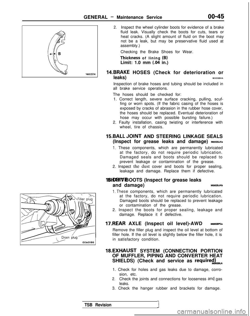
Checking the Brake Shoes for Wear. Thiclkness
of lining (B)
Limit: 1.0 mm
(.04 in.)
14.BRAKEI HOSES (Check for deterioration or
leaks)MOOSBHA
Inspection of brake hoses and tubing should be included in
all brake service operations.
The hoses should be checked for: 1. Correct length, severe surface cracking, pulling, scuf- fing or worn spots. (If the fabric casing of the hoses is
exposed by cracks of abrasion in the rubber hose cover,
the hoses should be replaced. Eventual deterioration of hose may occur with possible bursting failure.)
2. Faulty installation, casing twisting or interference with wheel, tire of chassis.
15.BALL ,IOINT AND STEERING LINKAGE SEALS
(Inspect for grease leaks and damage)
MOOSBJAa
I, These components, which are permanently lubricated at the factory, do not require periodic lubrication.Damaged seals and boots should be replaced to
prevent leakage or contamination of the grease.
2. Inspect the dust cover and boots for proper sealing, leakage and damage. Replace them if defective. 16.DRIVE SHAFT BOOTS (Inspect for grease leaks
and damage) MOOSWAb
1. The.se components, which are permanently lubricated
at the factory, do not require periodic lubrication.
Damaged boots should be replaced to prevent leakage
or contamination of the grease.
2. Inspect the boots for proper sealing, leakage and damage. Replace it if defective.
17.REAR AXLE (Inspect oil level)-AWD MOOSBPQ
Remove the filler plug and inspect the oil level at bottom of
filler hole. If the oil level is slightly below the filler hole, it is
in satisfactory condition. 18.EXHAIJST
SYSTEM (CONNECTION PORTION
OF MUFFLER, PIPING AND CONVERTER HEAT
SHIELDS) (Check and service as
require$LsBU
1. Check for holes and gas leaks due to damage, corro- sion, etc.
2.Check the joints and connections for looseness and gas
leaks.
3. Check the hanger rubber and brackets for damage.
TSB Revision1
Page 63 of 1273
ENGINE
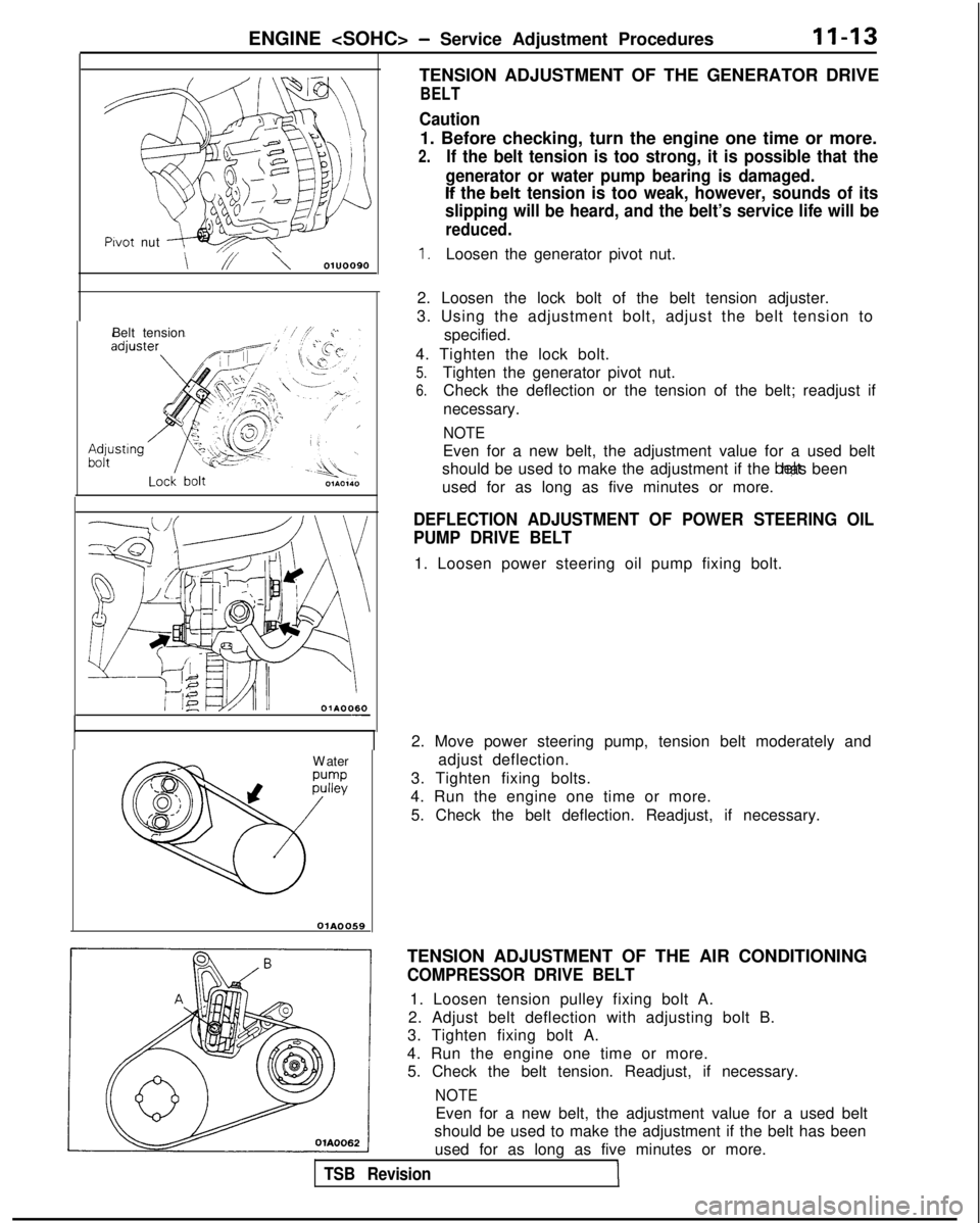
TENSION ADJUSTMENT OF THE GENERATOR DRIVE
BELT
Pwot
nut
,,,\
\ // \ 01u0090
Belt tension 01A0060
-
W
ater
OiA0059
Caution
1. Before checking, turn the engine one time or more.
2.If the belt tension is too strong, it is possible that the
generator or water pump bearing is damaged.
If the b’elt tension is too weak, however, sounds of its
slipping will be heard, and the belt’s service life will be
reduced.
1.Loosen the generator pivot nut.
2. Loosen the lock bolt of the belt tension adjuster.
3. Using the adjustment bolt, adjust the belt tension to
specified.
4. Tighten the lock bolt.
5.Tighten the generator pivot nut.
6.Check the deflection or the tension of the belt; readjust if
necessary.
NOTE
Even for a new belt, the adjustment value for a used belt
should be used to make the adjustment if the belt has been
used for as long as five minutes or more.
DEFLECTION ADJUSTMENT OF POWER STEERING OIL
PUMP DRIVE BELT
1. Loosen power steering oil pump fixing bolt.
2. Move power steering pump, tension belt moderately and adjust deflection.
3. Tighten fixing bolts.
4. Run the engine one time or more.
5. Check the belt deflection. Readjust, if necessary.
TENSION ADJUSTMENT OF THE AIR CONDITIONING
COMPRESSOR DRIVE BELT
1. Loosen tension pulley fixing bolt A.
2. Adjust belt deflection with adjusting bolt B.
3. Tighten fixing bolt A.
4. Run the engine one time or more. 5. Check the belt tension. Readjust, if necessary.
NOTE
Even for a new belt, the adjustment value for a used belt
should be used to make the adjustment if the belt has been
used for as long as five minutes or more.
TSB RevisionI
Page 112 of 1273
II-62ENGINE
Lock boltTENSION ADJUSTMENT OF THE GENERATOR DRIVE
BELT
Caution
1. Before checking, turn the engine one time or more.
2.If the belt tension is too strong, it is possible that the
generator or water pump bearing is damaged. If the belt tension is too weak, however, sounds of its slip-
ping will be heard, and the belt’s service life will be
reduced.
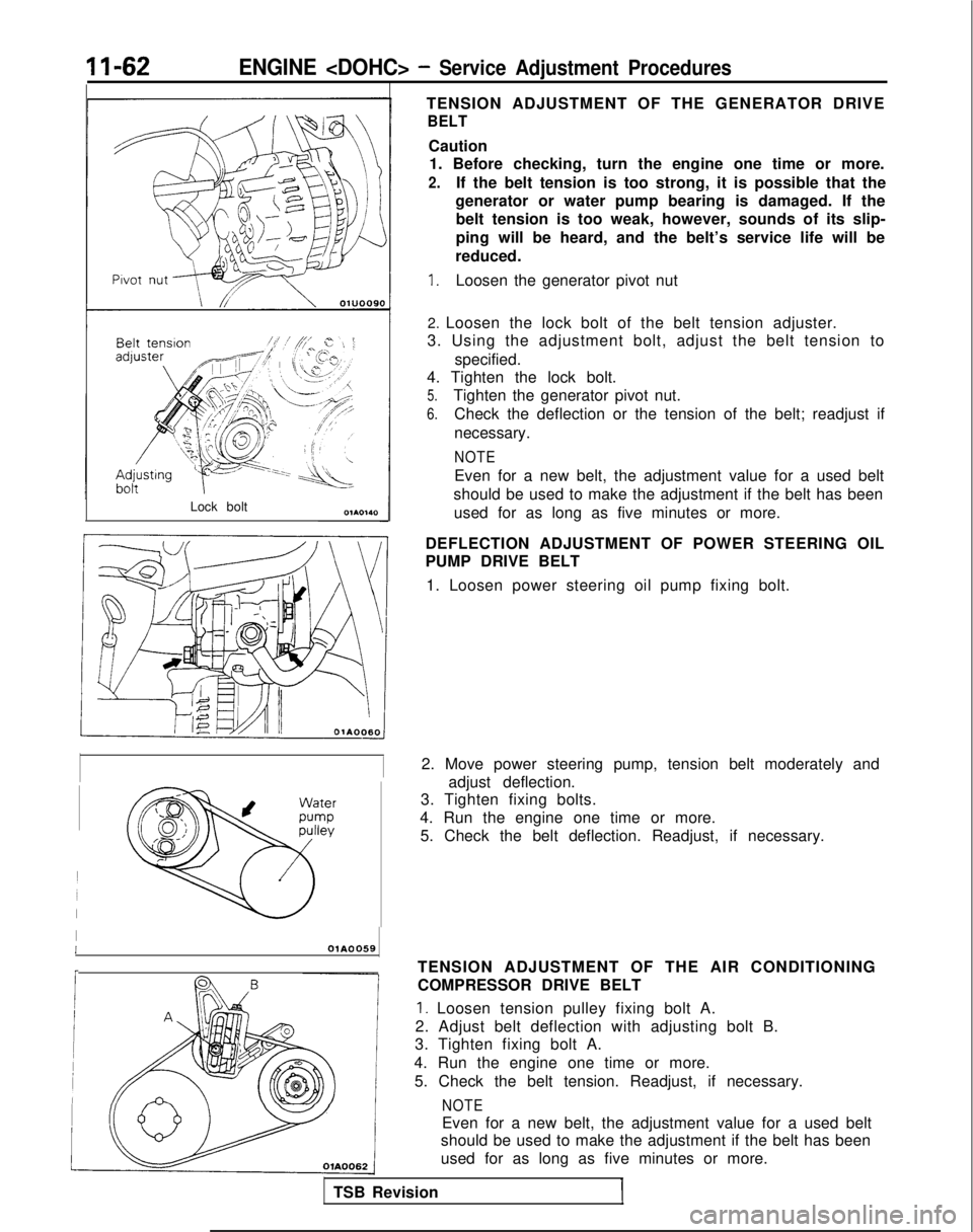
1.Loosen the generator pivot nut
2. Loosen the lock bolt of the belt tension adjuster.
3. Using the adjustment bolt, adjust the belt tension to
specified.
4. Tighten the lock bolt.
5.Tighten the generator pivot nut.
6.Check the deflection or the tension of the belt; readjust if
necessary.
NOTE
Even for a new belt, the adjustment value for a used belt
should be used to make the adjustment if the belt has been used for as long as five minutes or more.
DEFLECTION ADJUSTMENT OF POWER STEERING OIL
PUMP DRIVE BELT 1. Loosen power steering oil pump fixing bolt.
2. Move power steering pump, tension belt moderately and adjust deflection.
3. Tighten fixing bolts.
4. Run the engine one time or more. 5. Check the belt deflection. Readjust, if necessary.
IIOlA0059
r
TSB Revision TENSION ADJUSTMENT OF THE AIR CONDITIONING
COMPRESSOR DRIVE BELT
1. Loosen tension pulley fixing bolt A.
2. Adjust belt deflection with adjusting bolt B.
3. Tighten fixing bolt A.
4. Run the engine one time or more. 5. Check the belt tension. Readjust, if necessary.
NOTE
Even for a new belt, the adjustment value for a used belt
should be used to make the adjustment if the belt has been
used for as long as five minutes or more.
Page 117 of 1273
ENGINE
SERVICE POINTS OF REMOVAL
MllSBDF
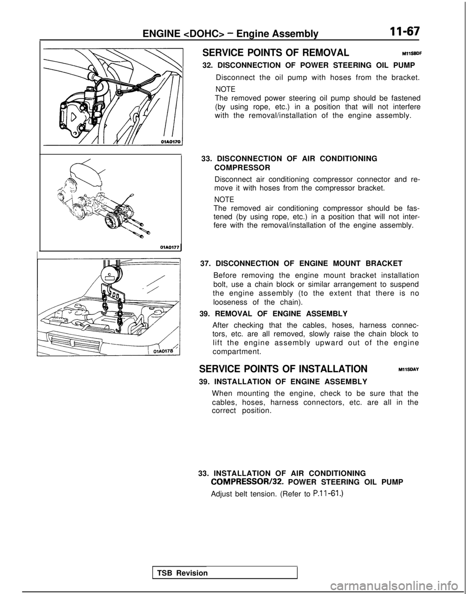
32. DISCONNECTION OF POWER STEERING OIL PUMP Disconnect the oil pump with hoses from the bracket.
NOTE
The removed power steering oil pump should be fastened(by using rope, etc.) in a position that will not interfere
with the removal/installation of the engine assembly.
33. DISCONNECTION OF AIR CONDITIONING COMPRESSOR
Disconnect air conditioning compressor connector and re-
move it with hoses from the compressor bracket.
NOTE
The removed air conditioning compressor should be fas-
tened (by using rope, etc.) in a position that will not inter-
fere with the removal/installation of the engine assembly. OlA0177
37. DISCONNECTION OF ENGINE MOUNT BRACKETBefore removing the engine mount bracket installation
bolt, use a chain block or similar arrangement to suspend
the engine assembly (to the extent that there is no
looseness of the chain).
39. REMOVAL OF ENGINE ASSEMBLY After checking that the cables, hoses, harness connec-
tors, etc. are all removed, slowly raise the chain block tolift the engine assembly upward out of the engine
compartment.
SERVICE POINTS OF INSTALLATION MllSDAY
39. INSTALLATION OF ENGINE ASSEMBLY When mounting the engine, check to be sure that thecables, hoses, harness connectors, etc. are all in the
correct position.
33. INSTALLATION OF AIR CONDITIONING
COMPRESSOR/32. POWER STEERING OIL PUMP
Adjust belt tension. (Refer to P.l l-61.)
TSB Revision
Page 120 of 1273
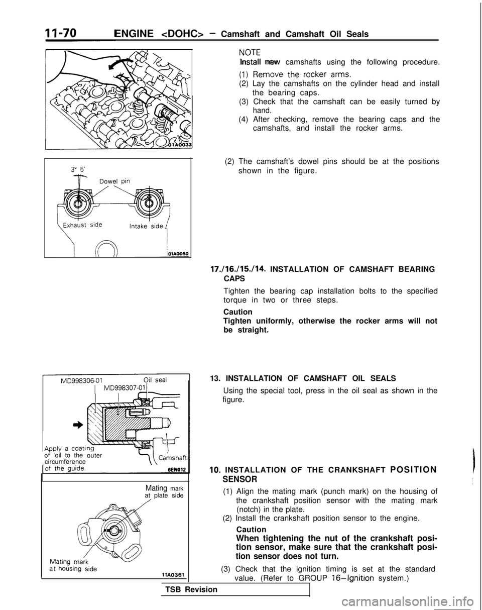
ENGINE
zI?mo”e the rocker arms.
Install new camshafts using the following procedure.
(2) Lay the camshafts on the cylinder head and install the bearing caps.
(3) Check that the camshaft can be easily turned by
hand.
(4) After checking, remove the bearing caps and the camshafts, and install the rocker arms.
3iF-Dowel Din
(2) The camshaft’s dowel pins should be at the positions
shown in the figure.
Intake.side
17./16./15./14. INSTALLATION OF CAMSHAFT BEARING
CAPS
Tighten the bearing cap installation bolts to the specified
torque in two or three steps.
Caution
Tighten uniformly, otherwise the rocker arms will not be straight.
ADDIY a coatioi ‘oil to the outer
circumferenceCahshaft
Mating markat plate side/
at hoising sidellA0361(3) Check that the ignition timing is set at the standard
value. (Refer to GROUP
16-Ignition system.)
TSB Revision 13. INSTALLATION OF CAMSHAFT OIL SEALS
Using the special tool, press in the oil seal as shown in the
figure.
10. INSTALLATION OF THE CRANKSHAFT POSITIO
N
SENSOR
(1) Align the mating mark (punch mark) on the housing of
the crankshaft position sensor with the mating mark(notch) in the plate.
(2) Install the crankshaft position sensor to the engine.
Caution
When tightening the nut of the crankshaft posi-
tion sensor, make sure that the crankshaft posi-
tion sensor does not turn.
Page 143 of 1273
13-1
FUEL
CONTENTSM’ISAA--
AUTO-CRUISE CONTROL SYSTEM.............
.
332
AUTO-CRUISE CONTROL ............................. 408
SERVICE ADJUSTMENT PROCEDURES .................397
Accelerator Cables
inspectron and Adjustment ........
.
398 Auto-cruise
Control System Inspection
..............397
Individual Parts Inspection ......................
401SPECfAL
TOOLS
.....................................
333
SPECIFICATIONS .................................... 332
TROUBLESHOOTING ................................. 334
Auto-cruise Control Components Location ..........368
Auto-cruise Control
Related Harnesses
..........365
Check Chart
Check Chart
Circuit Diagram ................................
371input Checking................................
.
366
On-board Diagnostic Checking ......................
361Troubleshooting Quick-reference Chart
.
334
Troubleshooting Quick-reference Chart
ENGINE CONTROL...............................
.
328
ENGINE CONTROL ..................................
330
SERVICE ADJUSTMENT PROCEDURES .................329
Accelerator Cable inspectron and Adjustment
...........329
Accelerator Switch Inspection and Adjustment ..........329
SPECIFICATIONS ....................................
328
TROUBLESHOOTlNG................................
.
328
Accelerator
Cable and Accelerator Pedal .............
.
328
FUEL SYSTEM
FUEL FILTER .........................................
327
FUEL LINE AND VAPOR LINE
.
326
FUEL LINE AND VAPOR LINE
.
324
FUEL TANK
.
322
FUELTANK
.
318
GENERAL INFORMATION ............................ 196
ON-VEHICLE INSPECTION OF MFI
COMPONENTS
......251
Air Conditioning Switch and A/C Compressor Clutch Relay .....................................
285
Barometric Pressure Sensor .................... 266
Boost Meter
311Camshaft Position Sensor ........................
.
277Closed Throttle Position Switch
.....................
.
274
Component Location .............................
251Components Inspection Pocedure
................. 255
Crankshaft Position Sensor ..................... 280EGR
Solenord
...................
.
307EGR Temperature Sensor
.............
.
288Engrne Control Module Power Ground
................
.
257
Engine Coolant Temperature Sensor ..................
268Evaporative Emission Purge Solenoid .................
.
307
Fuel Pressure Solenoid
307Fuel Pressure Test...............................
.
312
Fuel Pump ...................................... 258
Heated Oxygen Sensor ............................ 290
Idle Air Control Motor (Stepper Motor) ................
238Ignition Coil and Ignition Power Transistor .............
.
302
Ignition Switch-ST .................................. 284
Ignition Switch-ST and Park/Neutral Position Switch .....284
Injectors .......................................
295Inspection of Engine Control Module Terminal
Voltage .......................................
.
315
Intake Air Temperature Sensor .......................263
Knock Sensor
Power Steering Pressure Switch ......................
284Power Supply and Ignition Switch ...................
.
255Resistor
..............................
.
298Terminal Voltage Check Chart
......................
.
315Throttle Position Sensor
..........................
.
270Turbocharger Waste Gate Solenoid
.........
.
309 Vehicle
Speed Sensor
............................... 284
Volume Air Flow Sensor ............................
261SERVICE ADJUSTMENT PROCEDURES ...............
.
245
Basic
idle Speed Adjustment .......................
.
245
Closed Throttle Position Switch (Fixed
SAS)Adjustment ......................................
.
250
Curb
Idle Speed Inspection
..........................245Throttle Body (Throttle Valve Area) Cleaning
...........
.
248Throttle Position Sensor Adjustment
..................
.
248
SPECIALTOOLS...................................
.
204
SPECIFICATIONS ...................................
201TROUBLESHOOTING ...............................
.
205
Check Engine/Malfunction Indicator Lamp ..............205
Circuit Diagram .................................... 214
Clear Memory of Diagnostic Trouble Code .............
211Explanation and Precaution Related to Harness
Checking ......................................
.
205Explanation of Troubleshooting Procedures
............
.
205Failsafe/Back-up Functions List
.....................
.
211Fuel tank and Fuel Line
............................
.
244
Read Out Diagnostic Trouble Code ...................
211Troubleshooting Table
.............................
.
208(CONTINUED ON NEXT PAGE)
Page 144 of 1273
13-2
FUEL SYSTEM
..........
FUEL FILTER ....................................
FUEL LINE AND VAPOR LINE .....................FUELTANK....................................
.
GENERAL INFORMATION ........................
ON-VEHICLE INSPECTION OF MFI
COMPONENTS . .
Air
Conditionrng Switch and A/C CompressorClutch Relay ......
.
.............
Barometric Pressure Sensor .........
Camshaft Position Sensor ...........
Closed Throttle Position Switch ...........
Component Location .............
Components
Inspectron Procedure .......
.
Crankshaft Positron Sensor ............
EGR Solenoid
. . .3. .
115..,.113
. 109
. . 3
. . . 38
83
536961384173101EGR Temperature Sensor
.
85
Enqine Control Module Power Ground ......
.
....
45
Engine Coolant Temperature Sensor ...............
55Evaporative Emission Purge Solenord..............
.
99
Fuel Pressure ...............................
102Fuel Pump
...................................
.
46
Idle Speed Control Motor (DC Motor) ................
.
93
Idle Speed Control Motor Positron Sensor ............
.
64
lgnitron Co11 and Ignition Power Transistor .........
.
96
Ignition Switch-ST ..........................
77Ignition Switch-ST and Park/Neutral Position Switch
...78
Injectors..................................
.
90
Inspection of
Engrne Control Module Terminal
Voltage .........
.
..........................
105Intake Air Temperature Sensor ..................
.
51Oxygen Sensor
............................
.
87Power Steering Pressure Switch
..................
.
81Power Supply
.........................
.
42
Terminal Voltage Check Chart ......................
106Throttle Positron Sensor.....................
.
57Vehicle Speed Sensor
.........................
.
80
Volume Air Flow Sensor .........................
49
SERVICE ADJUSTMENT PROCEDURES .................
32
Basic
Idle Speed Adjustment ...................
.
33
Curb Idle Speed Inspection ..........................
32Throttle Body (Throttle Valve Area) Cleaning........
.
35
Throttle Positron Sensor Adjustment ................
35
SPECIAL TOOLS 7
.................
...................
SPECIFICATIONS ....................................
5
TROUBLESHOOTING .................................
8
Check Engine/Malfunction Indicator Lamp ..............
10Crrcuit Diagram.................................
.
20
Clear Memory of Diagnostic Trouble Code ............
17Explanation and Precaution Related to HarnessChecking......................................
.
9Explanation of Troubleshooting Procedures
...........
.
8
Failsafe/Back-up Functions List ....................
16Fuel Tank and Fuel Lrne.........................
.
32Read Out of Diagnostic Trouble Code
...............
.
16Troubleshooting Table
.........................
.
13
FUEL SYSTEM
116
FUEL FILTER .......................................
195
FUEL LINE AND VAPOR LINE ........................
195
FUEL TANK ........................................ 195
GENERAL INFORMATION ............................
116
ON-VEHICLE INSPECTION OF MFI
COMPONENTS
Air Conditioning Switch and A/C Compressor Clutch Relay .............................
Barometric Pressure Sensor .................
Camshaft Position Sensor ....................
Closed Throttle Position Switch ................
Component Location .......................
Components Inspectron Pocedure
..............
Crankshaft Position Sensor .................
EGR Solenoid
EGR Temperature Sensor
Engine Control Module Power Ground ..........
Engine Coolant Temperature Sensor .............
Evaporative Emission Purge Solenoid ............
Fuel Pressure Test ...........................
Fuel Pump ..................................
IAC Valve Positon Sensor
......................
Idle Air Control Motor (DC Motor) ..............
lgnrtion Coil and Ignition Power Transistor
.......
.
Ignition Switch-ST ...........................
Ignition Switch-ST and Park/Neutral Position Switch
Injectors ....................................
Inspection of Engine Control Module Terminal
Voltage .....................................
Intake Air Temperature Sensor .................
Oxygen Sensor .............................
Power Steering Pressure
Swatch..............
.
Power Supply ...............................
Terminal Voltage Check Chart ..................
Throttle Position Sensor .......................
Vehicle Speed Sensor ......................... . . . . 139
176
154
165
16013914216
7
..,_ 191177146
155
189192
147
162
184
186
171172181
192152
179
175
143
192
157
173
Volume Air Flow Sensor ...........................
.
150
SERVICE ADJUSTMENT PROCEDURES
...............
.
133
Basic Idle Speed Adjustment 133
Closed Throttle Position Switch and Throttle Position
Sensor Adjustment .................................
136Curb Idle Speed Inspection
.........................
.
133Fixed SAS Adjustment
.............................
.
138Throttle Body (Throttle Valve Area) Cleaning
...........
.
136
SPECIAL TOOLS
...................................
.
119
SPECIFICATIONS 118
.... ..............................
TROUBLESHOOTING ..................
.............
119
Check Engine/Malfunction Indicator Lamp ..............
120Circuit Diagram...................................
.
128Clear Memory of Diagnostic Trouble Code
............
.
126Explanation and Precaution Related to Harness
Checking ........................................
.
119Explanation of Troubleshooting Procedures
............
.
119Failsafe/Back-up
Fuctions List
........................
126
Fuel Tank and Fuel Line .............................
133Read Out of Diagnostic Trouble Code ................
.
126
Troubleshooting Table ..............................
123
Page 189 of 1273
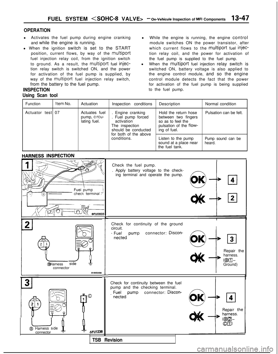
FUEL SYSTEM
OPERATION
l
Activates the fuel pump during engine cranking
and while the engine is running.
l When the ignition switch is set to the START
position, current flows, by way of the
multiport
fuel injection relay coil, from the ignition switch
to ground. As a result, the
multiport fuel injec-
tion relay switch is switched ON, and the power
for activation of the fuel pump is supplied, by
way of the
multiport fuel injection relay switch,
from the battery to the fuel pump.
INSPECTION
Using Scan tool
l While the engine is running, the engine control
module switches ON the power transistor, after
which current flows to the
multiport fuel injec-
tion relay coil, and the power for activation of
the fuel pump is supplied to the fuel pump.
l When the
multiport fuel injection relay switch is
switched ON, battery voltage is also applied to
the engine control module, and so the engine
control module detects the fact that the power
for activation of the fuel pump is being supplied
to the fuel pump.
Function Item
No.
Actuation Inspection conditions DescriptionNormal condition
Actuator test 07 Actuates fuel
. Engine cranking Hold the return hosePulsation can be felt.
pump, clrcu-
. Fuel pump forced between two fingers
lating fuel. activation
so as to feel the
The inspection pulsation of the
flow-should be conducteding of fuel.
for both of the above conditions. Listen to the pump
Pump sound can besound at a place nearheard.the fuel tank.
Check for continuity of the ground
circuit.
I
. ;E;;,, pumpconnector: Discon-
2
1
Y-
!
Repair theharness.
@El- @ HarnessGround)connector
O~AOZOl3
I
Check for continuity between the fuel
pump and the checking terminal.
connector: Discon-
1
@uide 1
B
0. ;;;;,,
pump
L
Check the fuel pump.
. Apply battery voltage to the check-
ing terminal and operate the pump.
!I:7
OK
connector :1 = 6FUl238
TSB Revision