1989 MITSUBISHI GALANT checking oil
[x] Cancel search: checking oilPage 442 of 1273
FUEL SYSTEM
of
MFI Components
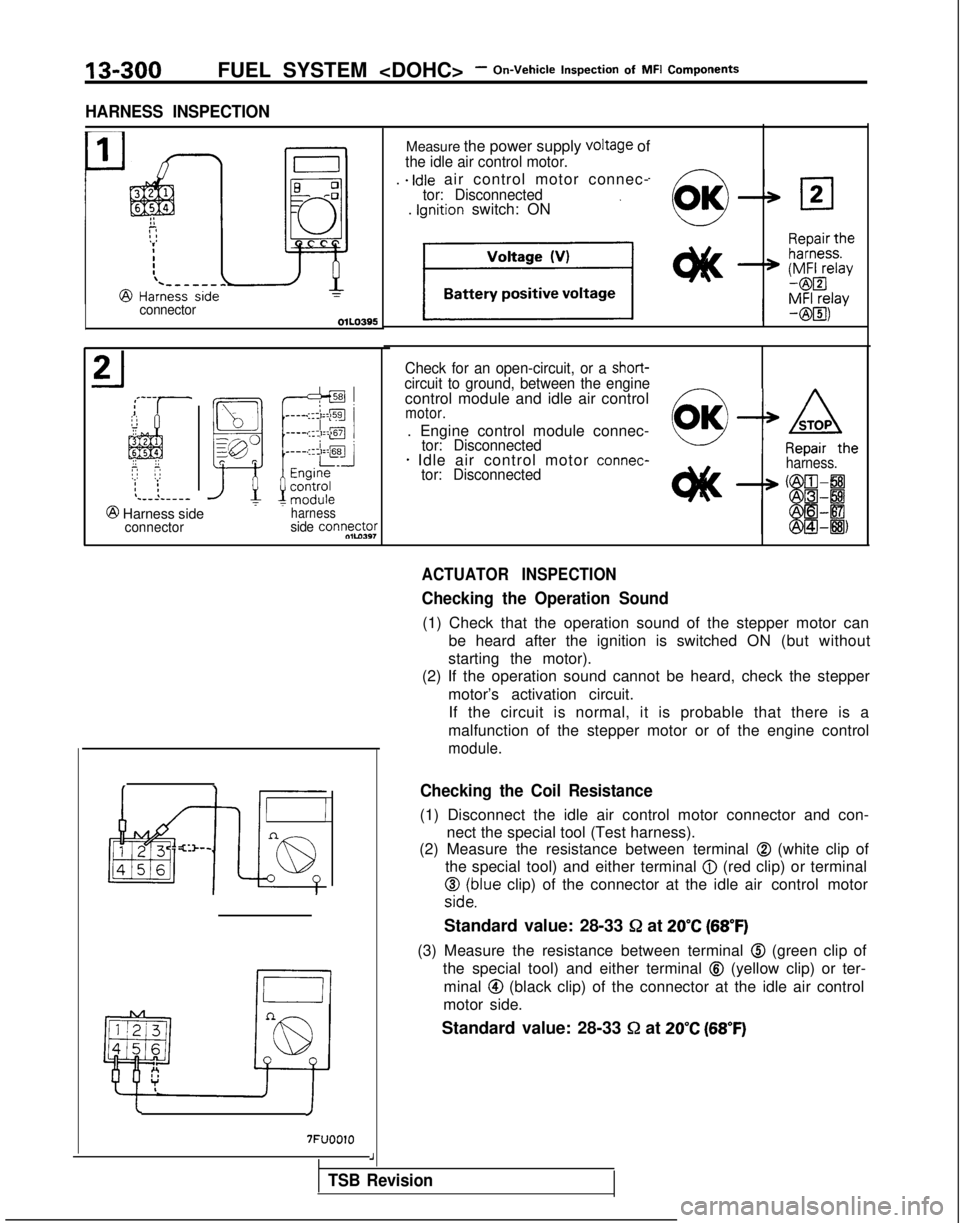
HARNESS INSPECTION
connector
@ Harness side7
connectorharnessside connw&
cI
7FUOOlO
Measure the power supply VOltage ofthe idle air control motor.
. e Idle air control motor connec-tor: Disconnected. Ignition switch: ON
Check for an open-circuit, or a short-circuit to ground, between the enginecontrol module and idle air controlmotor.
. Engine control module connec-tor: Disconnected* Idle air control motor connec-‘--R&heharness.tor: Disconnected
ACTUATOR INSPECTION
Checking the Operation Sound
(1) Check that the operation sound of the stepper motor can
be heard after the ignition is switched ON (but without
starting the motor).
(2) If the operation sound cannot be heard, check the stepper
motor’s activation circuit.If the circuit is normal, it is probable that there is a
malfunction of the stepper motor or of the engine control
module.
Checking the Coil Resistance
(1) Disconnect the idle air control motor connector and con- nect the special tool (Test harness).
(2) Measure the resistance between terminal
@ (white clip of
the special tool) and either terminal
@ (red clip) or terminal
$d;!lue clip) of the connector at the idle air control motor
Standard value: 28-33 &
at
20°C (68°F)
(3) Measure the resistance between terminal @ (green clip of
the special tool) and either terminal
@ (yellow clip) or ter-
minal
@ (black clip) of the connector at the idle air control
motor side.
Standard value: 28-33
51 at 20°C (68°F)
J
TSB Revision
Page 458 of 1273
13-316FUEL SYSTEM
Inspection
of
MFI
Components
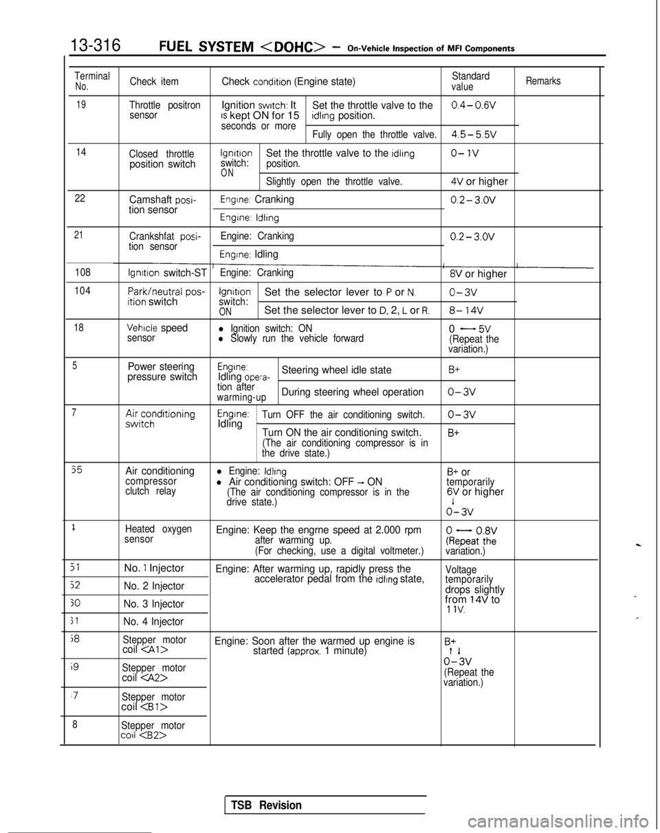
TerminalNo.Check itemCheck condition (Engine state)Standardvalue
Remarks
19Throttle positronIgnition switch: ItSet the throttle valve to the0.4- 0.wsensorIS kept ON for 15seconds or moreidlrng position.
Fully open the throttle valve.4.5- 5.5v
14
Closed throttlelgnrtrono-1vposition switchswitch:Set the throttle valve to the idling
position.
ONSlightly open the throttle valve.4V or higher
22Camshaft posi-tion sensorEngine: Cranking0.2- 3.ov
Engine: ldlrng
21
Crankshfat posi-tion sensor Engine: Cranking0.2- 3.ov
Engine: Idling
108lgnrtion switch-STEngine: Cranking8V or higher
104
Park/neutral
pos-ition switchIgnitionSet the selector lever to P or N.o-3vswitch:ONSet the selector lever to D, 2, L or R.8- 14V
18Vehicle speedl Ignition switch: ON
sensorl Slowly run the vehicle forward0 - 5v(Repeat the
variation.)
5Power steering
pressure switchEngine:Idling opera-Steering wheel idle stateB+
tion afterwarming-upDuring steering wheel operationo-3v
7A&;;;ditioningEngine:Idling _Turn OFF the air conditioning switch.o-3v
Turn ON the air conditioning switch.B+
(The air conditioning compressor is in
the drive state.)
35Air conditioningl Engine: IdlingB+ orcompressor
clutch relayl Air conditioning switch: OFF -, ON(The air conditioning compressor is in the
temporarily
drive state.)6V or higher o’-
3v
1Heated oxygen
sensorEngine: Keep the engrne speed at 2.000 rpmafter warming up.
(For checking, use a digital voltmeter.)ke;atoZivariation.)
51No. 1 InjectorEngine: After warming up, rapidly press the
52No. 2 Injector accelerator pedal from the idlrng state,Voltage
temporarily
drops slightly
30No. 3 Injectorfrom 14V to1 IV.
51No. 4 Injector
j8
Stepper motorcoil
i9
Stepper motor0%
coil
variation.)
‘7Stepper motorcoil
8Stepper motorco11
TSB Revision
Page 485 of 1273
AUTO-CRUISE CONTROL SYSTEM - Troubleshooting
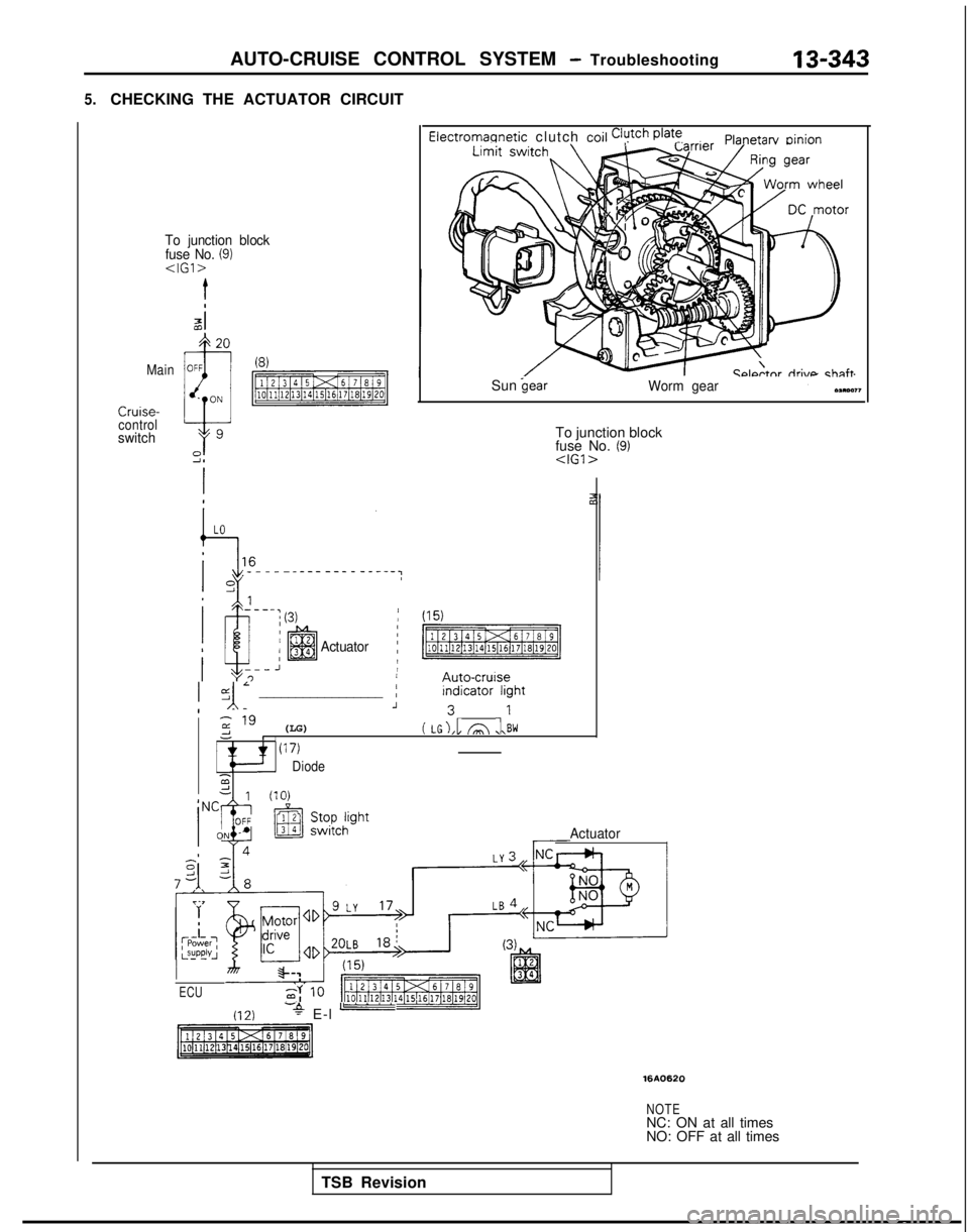
5.CHECKING THE ACTUATOR CIRCUIT
Electromannetic clutch coil Clutch @at’!Planetarv oinion
To junction block
fuse No. (9)
Ccdtnr riri\mchnftMainSun
control
switchTo junction block
fuse No. (9)
Actuator
/ (15)
p$%Emig
jyl; _________________ ;F:;;:ght
z " (LG)-1( LG),l A ,l\BWI(17)
Diode2d 111n\
Actuator
ECU
(12)-+ E-l -
1610620
NOTENC: ON at all times
NO: OFF at all times
TSB Revision
Page 544 of 1273
13-402AUTO-CRUISE CONTROL SYSTEM - service Adjusbnent PWSXIU~S
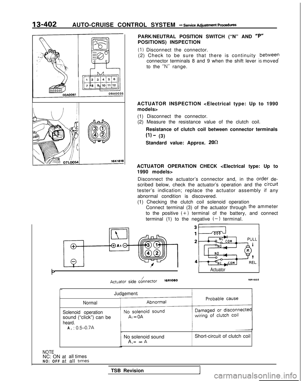
PARK/NEUTRAL POSITION SWITCH (“N” AND “P”
POSITIONS) INSPECTION
(1) Disconnect the connector.
(2) Check to be sure that there is continuity ,between
connector terminals 8 and 9 when the shift lever IS moved
to the “N”
range.
ACTUATOR INSPECTION
(1) Disconnect the connector.(2) Measure the resistance value of the clutch coil.
Resistance of clutch coil between connector terminals
(1) - (3)
Standard value: Approx.
2Ofl
ACTUATOR OPERATION CHECK
Disconnect the actuator’s connector and, in the
ordey de-
scribed below, check the actuator’s operation and the clrcult
tester’s indication; replace the actuator assembly if any
abnormal condition is discovered.
(1) Checking the clutch coil solenoid operation Connect terminal (3) of the actuator through the
ammeter
to the positive
(+) terminal of the battery, and connect
terminal (1) to the negative
(-) terminal.
Actuator
Actuator side cO/nectOr16R10801SR1032
rJudaement
Normal
Solenoid operation
sound (“click”) can be
heard.
T
-t
A, : 0.5-0.7A
NOTENC: ON at all times No solenoid sound
A,=
mA
Short-circuit of clutch coil
NO: OFF at all
times
TSB RevisionI
Page 545 of 1273
AUTO-CRUISE CONTROL SYSTEM - Service Adjustment procedures13-403
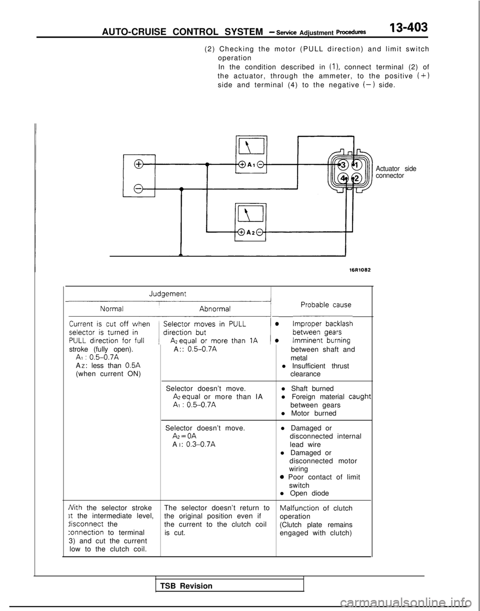
(2) Checking the motor (PULL direction) and limit switch
operation
In the condition described in
(1). connect terminal (2) of
the actuator, through the ammeter, to the positive
(+)
side and terminal (4) to the negative (-) side.
Actuator side
connector
16R1082
~1 L-E~~~~~~
stroke (fully open). A:: 0.5-0.7Abetween shaft andAI : 0.5-0.7Ametal
A Z: less than 0.5A
l Insufficient thrust
(when current ON) clearance
Selector doesn’t move. l Shaft burned Azequal
or more than IA l Foreign material
caugt
AI : 0.5-0.7Abetween gears
l Motor burned
Selector doesn’t move. Az=OA
A I:
0.3-0.7A
l Damaged or
disconnected internal
lead wire
l Damaged or disconnected motor
wiring
0 Poor contact of limit
switch
l Open diode
Nith the selector stroke The selector doesn’t return toMalfunciion of clutch3t the intermediate level,
the original position even if
operationdisconnect
the
the current to the clutch coil
(Clutch plate remains
:onnection to terminalis cut. engaged with clutch)
3) and cut the current
low to the clutch coil.
1t
TSB Revision
Page 674 of 1273
22-10MANUAL TRANSAXLE
e
TRANSAXLE
REMOVAL AND INSTALLATION
MZMA-A
27-34 Nm20-25 ft.lbs.
60-80
Nm*
43-58 ft.lbs.*
11-16
ft.lbs.71
11-16 ftlbs.
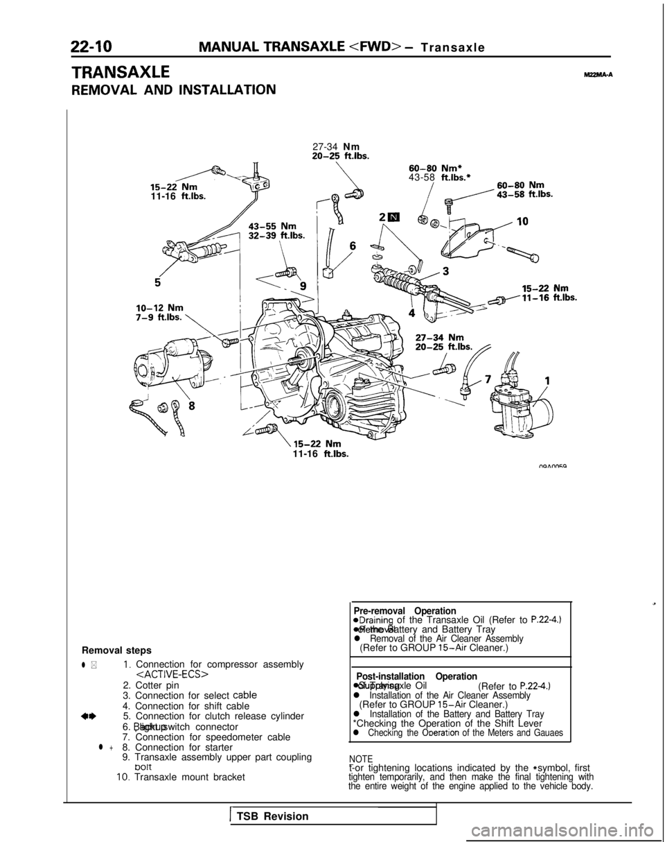
Removal steps
l *1, Connection for compressor assembly
2. Cotter pin
3. Connection for select cable
4. Connection for shift cable
a*5. Connection for clutch release cylinder
6. backup light switch connector
7. Connection for speedometer cable
l +8. Connection for starter
9. Transaxle assembly upper part coupling
tJ01t10. Transaxle mount bracket
Pre-removal Operation@Draining of the Transaxle Oil (Refer to P.22-4.) *Removal of the Battery and Battery Tray
l Removal of the Air Cleaner Assembly(Refer to GROUP 15-Air Cleaner.)
Post-installation Operation
asupplying of Transaxle Oil
(Refer to P.224.)l Installation of the Air Cleaner Assembly(Refer to GROUP 15-Air Cleaner.)l Installation of the Battery and Battery Tray*Checking the Operation of the Shift Leverl Checking the Ooeration of the Meters and Gauaes
NOTE
-t-or tightening locations indicated by the * symbol, firsttighten temporarily, and then make the final tightening with
the entire weight of the engine applied to the vehicle body.
1TSB Revision
Page 684 of 1273
22-20MANUAL TRANSAXLE
TRANSAXLE
REMOVAL AND INSTALLATIONMZMA-B
l Removal of the Battery and Battery Tray*Removal of the Air Cleaner Assembly
(Refer to GROUP 15-Air Cleaner.)
15-22
Nm11-16 ft.lbs.-
lo-12 Nm7-8 ft.lbs.;
Post-installation Operation@Supplying of Transaxle Oil (Refer to P.22-18.)l Installation of the Air Cleaner Assembly(Refer to GROUP 15-Air Cleaner.)*Installation of the Battery and BatteryTray*Checking the Operation of the ShiftLever*Checking the Operation of the Metersand Gauges
60-80
Nm*
27-34
Nm43-58ft.lbs.*
20-25ft.lbs.60-80Nm
43-55 Nm _
15-22’ Nm11-16 ft.lbs.
6
-15-22 Nm11-16 ftlbs.
09AOOS4
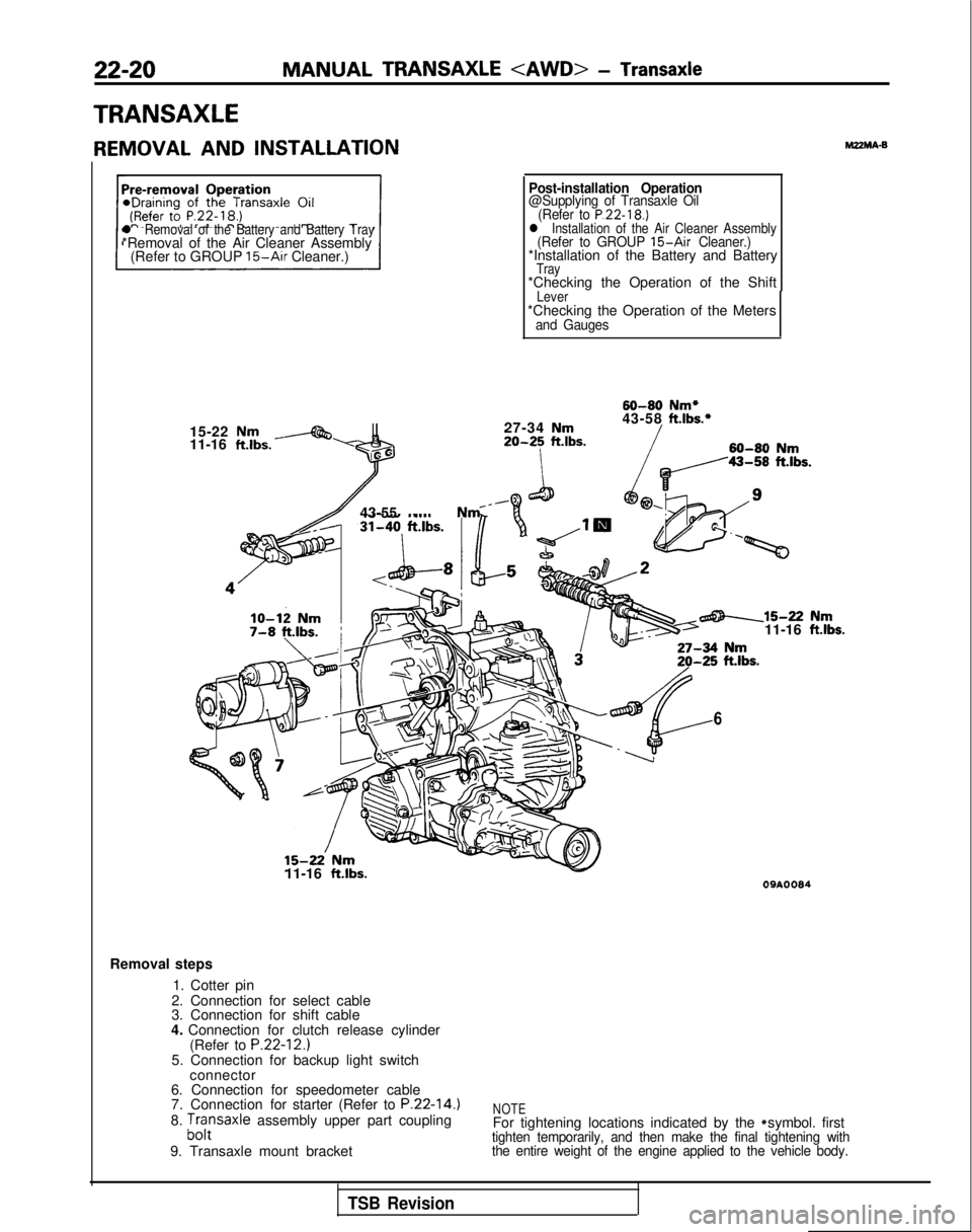
Removal steps
1. Cotter pin
2. Connection for select cable
3. Connection for shift cable
4. Connection for clutch release cylinder (Refer to
P.22-12.)5. Connection for backup light switchconnector
6. Connection for speedometer cable
7. Connection for starter (Refer to
P.22-14.)8. ;,,:saxle assembly upper part coupling
9. Transaxle mount bracketNOTEFor tightening locations indicated by the * symbol. firsttighten temporarily, and then make the final tightening with
the entire weight of the engine applied to the vehicle body.
TSB Revision
Page 740 of 1273
23-34AUTOMATIC TRANSAXLE - Troubleshooting
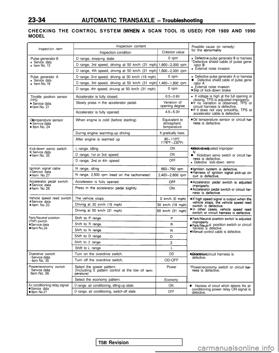
CHECKING THE CONTROL SYSTEM (WHEN
A SCAN TOOL IS USED) FOR 1989 AND 1990
MODEL
Pulse generator Al Service datal Item No. 1’9
Throttle positron sensorTPS)m Service dataD Item No. 21
I!(
(44
c44
I!.,
I(,
\,4
:44 C
.
.
F.
.
A00
D range, stopprng state 0 rpml Defectrve pulse generator B or harness
D range, 3rd speed, driving at 50 km/h (31 mph) 1.600-2.000
rpm*Defective shield cable of pulse gene-
rator B
D range, 4th speed, drivrng at 50 km/h (31 mph) 1.600-2.000
rpml External noise invasion
D range. 2nd speed, driving at 30 km/h (19 mph) 0 rpml Defective pulse generator A or harness
D range, 3rd speed, driving at 50 km/h (31 mph) 1.400-1.800
rpml Defective shield cable of pulse gene-rator A
D range, 4th speed, drivrng at 50 km/h (31 mph) 0 rpml External noise Invasion *Slip
of kick-down brake
Accelerator is fully closed. 0.5-0.6V
l If voltage is high at the full opening or
Slowly press In the accelerator pedal.Variatron of
closing, TPS is adjusted improperly.
opening degreeelf no variation is observed, TPS or
circuit harness is defective.
Accelerator is fully opened.
4.5-5.ovelf it does not vary smoothly, TPS or
accelerator cable is defective. Xl temperature sensor
) Servtce data) Item No. 24
When engtne is cold (before starting)
Equivalent toatmospheric
temperature *Oil
temperature sensor or circuit har-ness is defective.
cickdown servo switch) Servrce data1 Item No. 25
Durrng engine warming-up driving
After engine is warmed up
L range. idling
D range, 1st or 3rd speed
D range, 2nd or 4th speed
It gradually rises.
80- 110°C(176”F-230°F)
ON *Kick-down servo IS adjusted improper-
ONIV.l Kickdown servo switch or circuit har-
OFFness is defective.l Defectivekick-down
servo
bItem No.34 alposition switch or circuitharness is defective.*Manual
control cable is defective.
Iverdnve switch1 Servrce data1 item No. 35
‘owedeconomy swatch‘Servrce data
Item No. 36 Shift to
L range
Turn on the overdrive switch.
Turn off the overdrive switch.
Select the power pattern. (Including
E pattern control at the low oil tem-perature)
L
OD
OD-OFF
Power moverdrive switch or circuit harness is
defective.
*Power/economy switch or circuit har-ness is defective.
Select the economy pattern.
Economy
.ir conditioning relay signalService dataD range. air conditioning, idling-up stateONl Harness of circuit which detects the air
Item No.37D range, air conditioning, switch-off stateOFFconditioning power relay ON signal isdefective.
Inspectron ttemInspectron content
Inspection conditionPossible cause (or remedy)
Criterion value for the abnormalrty
Pulse generator Bl Service datal Item No. 13
TSB Revision