1989 MITSUBISHI GALANT drain bolt
[x] Cancel search: drain boltPage 45 of 1273
GENERAL - Maintenance Service00-43
1
O.AUTOMATIC
TRANSAXLE
Inspect fluid levelMOOSSDA
1. Drive until the fluid temperature reaches the usual ternperature
[70-80°C (160- 18O”F)I.
2. Plaice vehicle on level floor.
3.Move selector lever sequentially to every position to fill
torque converter and hydraulic circuit with fluid, then place lever in “N” Neutral position. This operation is
necessary to be sure that fluid level check is accurate.
4. Before removing dipstick, wipe all dirt from area around
dipstick. Then take out the dipstick and check the
condition of the fluid.
The transaxle should be overhauled under the following
conditions.l If there is a “burning” odor.
l If the fluid color has become noticeably blacker.
l If there is a noticeably great amount of metal particles in the fluid.
5.Chleck to see if fluid level is in “HOT” range on dipstick.
If fluid level is low, add ATF until level reaches “HOT”
range.
LO\N fluid level can cause a variety of conditions
because it allows pump to take in air along with fluid. Air
trapped in hydraulic circuit forms bubbles which make
fluid spongy. Therefore, pressures will be erratic. Improper filling can also raise fluid level too high. When
transaxle has too much fluid, gears churn up foam and cause same conditions which occur with low fluid level,
resulting in accelerated deterioration of ATF.In either case, air bubbles can cause overheating, fluid
oxidation, which can interfere with normal valve, clutch,
and servo operation. Foaming can also result in fluid escaping from transaxle vent where it may be mistaken
for a leak.
6. Be sure to examine fluid on dipstick closely. Chaqge
fluid
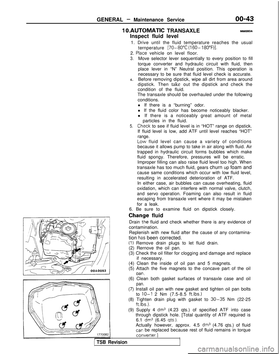
Drain
tlhe fluid and check whether there is any evidence of
contamination. Replenish with new fluid after the cause of any contamina-
tion
has been corrected.
(1) Rernove drain plugs to let fluid drain.
(2) Rernove the oil pan.
(3) Check the oil filter for clogging and damage and replace
if necessary.
(4) Clean the inside of oil pan and 5 magnets.
(5) Attach the five magnets to the concave part of the oil
pan.
1 TSB Revision
(6) Clean both gasket surfaces of transaxle case and oil
pan.
(7) Install oil pan with new gasket and tighten oil pan bolts
to
IO-I 2 Nm (7.5-8.5 ftlbs.)
(8) Tighten drain plug with gasket to 30-35 Nm (22-25 ft.lbs.).
(9) Supply 4
dm3 (4.23 qts.) of specified ATF into case
through dipstick hole. [Total quantity of ATF required is 6.1
dm3 (6.45 qts.).
Actually however, approx. 4.5 dm3 (4.76 qts.) of fluid
car1 be replaced because rest of fluid remains in torque converter.]
1
Page 54 of 1273
II-4ENGINE
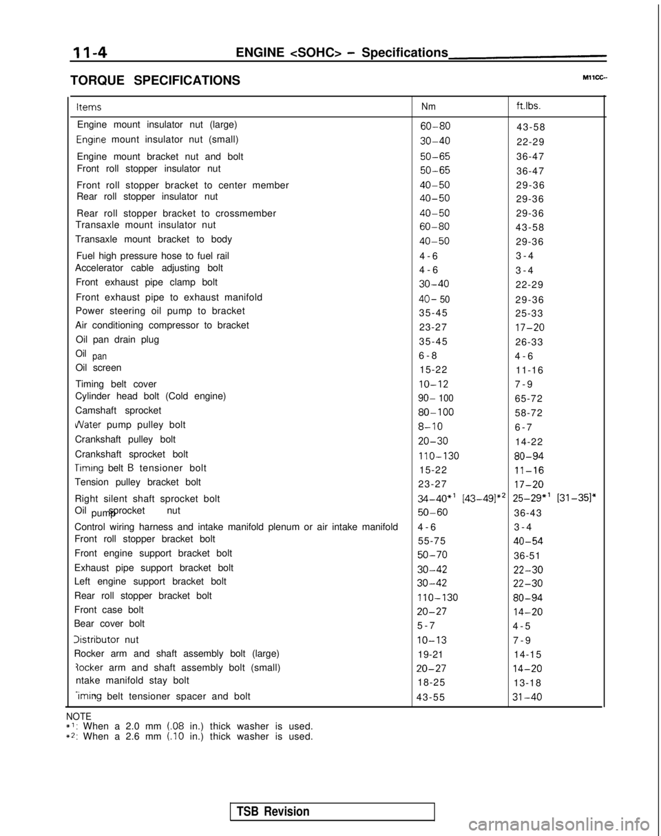
TORQUE SPECIFICATIONS Items
Nm ft.lbs.
Engine mount insulator nut (large)
60-8043-58
Engrne mount insulator nut (small)30-4022-29
Engine mount bracket nut and bolt
50-6536-47
Front roll stopper insulator nut
50-6536-47
Front roll stopper bracket to center member
40-5029-36
Rear roll stopper insulator nut
40-5029-36
Rear roll stopper bracket to crossmember
40-5029-36
Transaxle mount insulator nut
60-8043-58
Transaxle mount bracket to body
40-5029-36
Fuel high pressure hose to fuel rail 4-
6
3-4
Accelerator cable adjusting bolt 4-63-4
Front exhaust pipe clamp bolt
30-4022-29
Front exhaust pipe to exhaust manifold
40- 5029-36
Power steering oil pump to bracket 35-4525-33
Air conditioning compressor to bracket 23-27
17-20
Oil pan drain plug35-4526-33
Oilpan6-
8
4-6
Oil screen 15-2211-16
Timing belt cover
IO-127-
9
Cylinder head bolt (Cold engine)
90- 10065-72
Camshaft sprocket
80-10058-72
dater pump pulley bolt8-106-
7
Crankshaft pulley bolt
20-3014-22
Crankshaft sprocket bolt
110-13080-94
Timrng belt B tensioner bolt 15-2211-16
Tension pulley bracket bolt 23-2717-20
Right silent shaft sprocket bolt34-40”’ [43-49]*’ 25-29” [31-351”
Oil sprocket nut pump
50-6036-43
Control wiring harness and intake manifold plenum or air intake manifold\
4-
6
3-4
Front roll stopper bracket bolt 55-75
40-54
Front engine support bracket bolt50-7036-51
Exhaust pipe support bracket bolt
30-4222-30
Left engine support bracket bolt30-4222-30
Rear roll stopper bracket bolt110-13080-94
Front case bolt20-2714-20
Bear cover bolt 5-
7
4-5
Iistributor nutIO-137-
9
Rocker arm and shaft assembly bolt (large) 19-2114-15
?ocker arm and shaft assembly bolt (small)20-2714-20
ntake manifold stay bolt
18-2513-18
-iming belt tensioner spacer and bolt
43-5531-40
NOTE*I: When a 2.0 mm (.08 in.) thick washer is used.~2: When a 2.6 mm (.I0 in.) thick washer is used.
TSB Revision
Page 73 of 1273
ENGINE
OIL PAN
AND
OIL SCREENMllHA-A
REMOVAL AND INSTALLATION
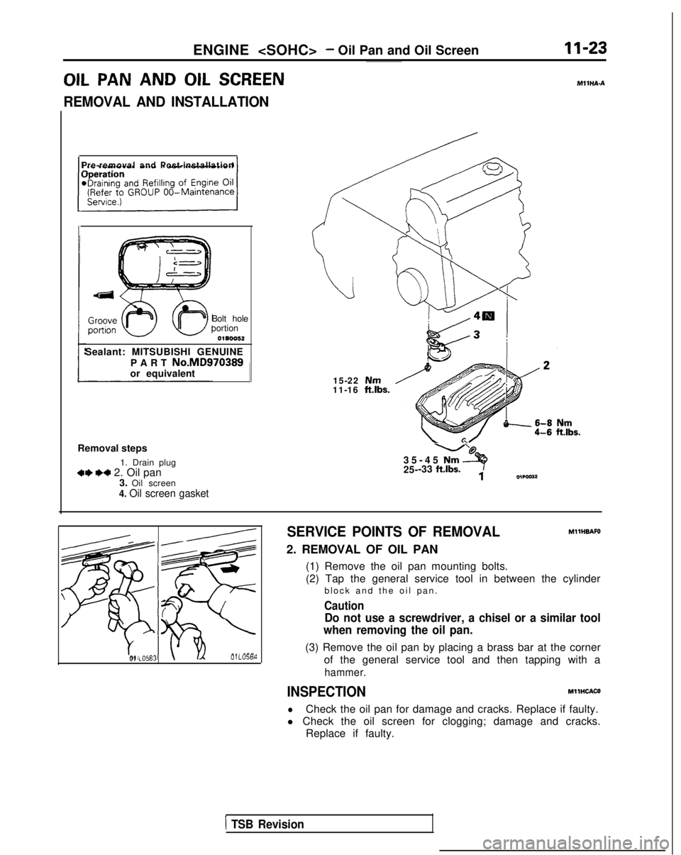
Pre-removal and Post-installation
Bolt hole
portion
0180052
Sealant: MITSUBISHI GENUINE
PART
No.MD970389or equivalent
Removal steps 1. Drain plug
4**4 2. Oil pan3. Oil screen
4. Oil screen gasket
15-22 Nm11-16 ft.lbs.
U’@
35-45 Nm a25- -33 ft.lbs.iowaI32
d- -<
--,\9 -
\’ 63
%e
;
01 LO583\01 LO584
SERVICE POINTS OF REMOVALMllHBAFO
2. REMOVAL OF OIL PAN
(1) Remove the oil pan mounting bolts.
(2) Tap the general service tool in between the cylinderblock and the oil pan
.
Caution
Do not use a screwdriver, a chisel or a similar tool
when removing the oil pan.
(3) Remove the oil pan by placing a brass bar at the corner
of the general service tool and then tapping with a
hammer.
INSPECTIONMllHCACO
lCheck the oil pan for damage and cracks. Replace if faulty.
l Check the oil screen for clogging; damage and cracks. Replace if faulty.
1 TSB Revision
Page 104 of 1273
11-54ENGINE
Items For air conditioning compressor DeflectionInspection
New belt
Used belt
Tension
Inspection
New belt
Used belt
For power steering pump
DeflectionInspection
Timing belt Amount of projection of auto tensioner rod
Timing belt “B” tension
Amount of projection of auto tensioner rod (distance between the tensioner arm and
auto tensioner body)
Auto tensioner rod retraction Standard Value
mm (in.) Approx. 8
(.315)
5.0-5.5 (.197-,217)
6.0-7.0 (.236-.276)
N (Ibs.)
250-500 (55-l 10)
470-570 (104-126)
320-400 (71-88)
mm (in.)
6.9-9.0 (.236-,354)
mm (in.) 12 (.47)
mm (in.) 5-7 (.20-.28)
mm (in.) 3.8-4.5 (.15-.18)
rpm 2.5-
3
Limit
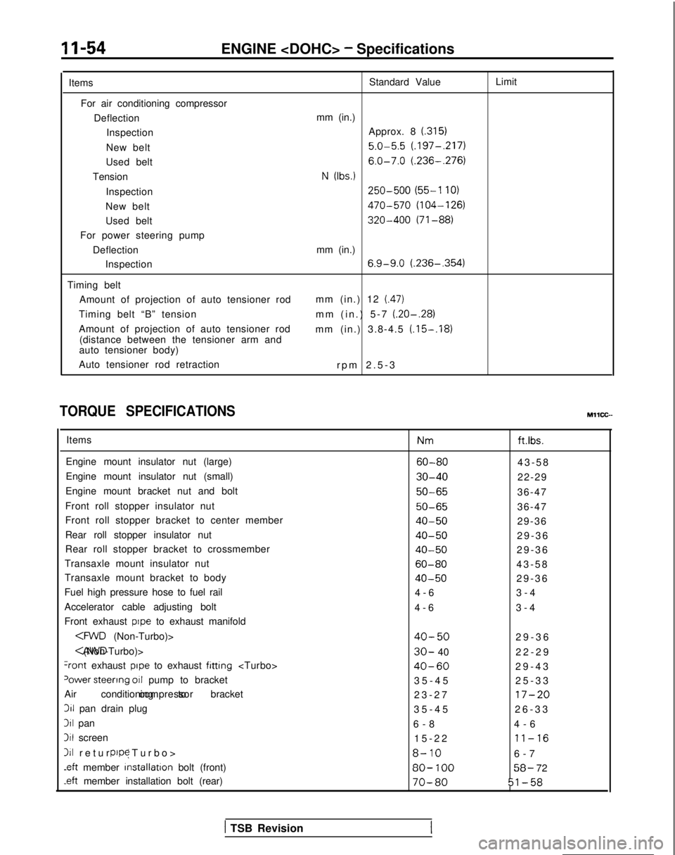
TORQUE SPECIFICATIONS
Items
Engine mount insulator nut (large)
Engine mount insulator nut (small)
Engine mount bracket nut and bolt
Front roll stopper insulator nut
Front roll stopper bracket to center member
Rear roll stopper insulator nut
Rear roll stopper bracket to crossmember
Transaxle mount insulator nut
Transaxle mount bracket to body
Fuel high pressure hose to fuel rail
Accelerator cable adjusting bolt
Front exhaust
pope to exhaust manifold
+ont exhaust pope to exhaust fitting
‘ower steerrng 011 pump to bracket
Air conditioning to bracket compressor311
pan drain plug
311 pan
3il screen
111 return (Turbo
>
pope
.eft
member installation
bolt (front)
-eft member installation bolt (rear) Nm
ft.ibs.
60-8043-5
8
30-4022-29
50-6536-47
50-6536-47
40-5029-36
40-5029-3
6
40-5029-3
6
60-8043-5
8
40-5029-3
6
4-6 3-4
4-6 3-4
40-5029-3
6
30- 40
22-2
9
40-6029-4
3
35-45 25-33
23-27
17-20
35-4
5
26-33
6-8 4-6
15-22
11-16
8-106-
7
80-
10058- 72
70-8051-58
MllCC--
( TSB Revision
Page 148 of 1273
13-6
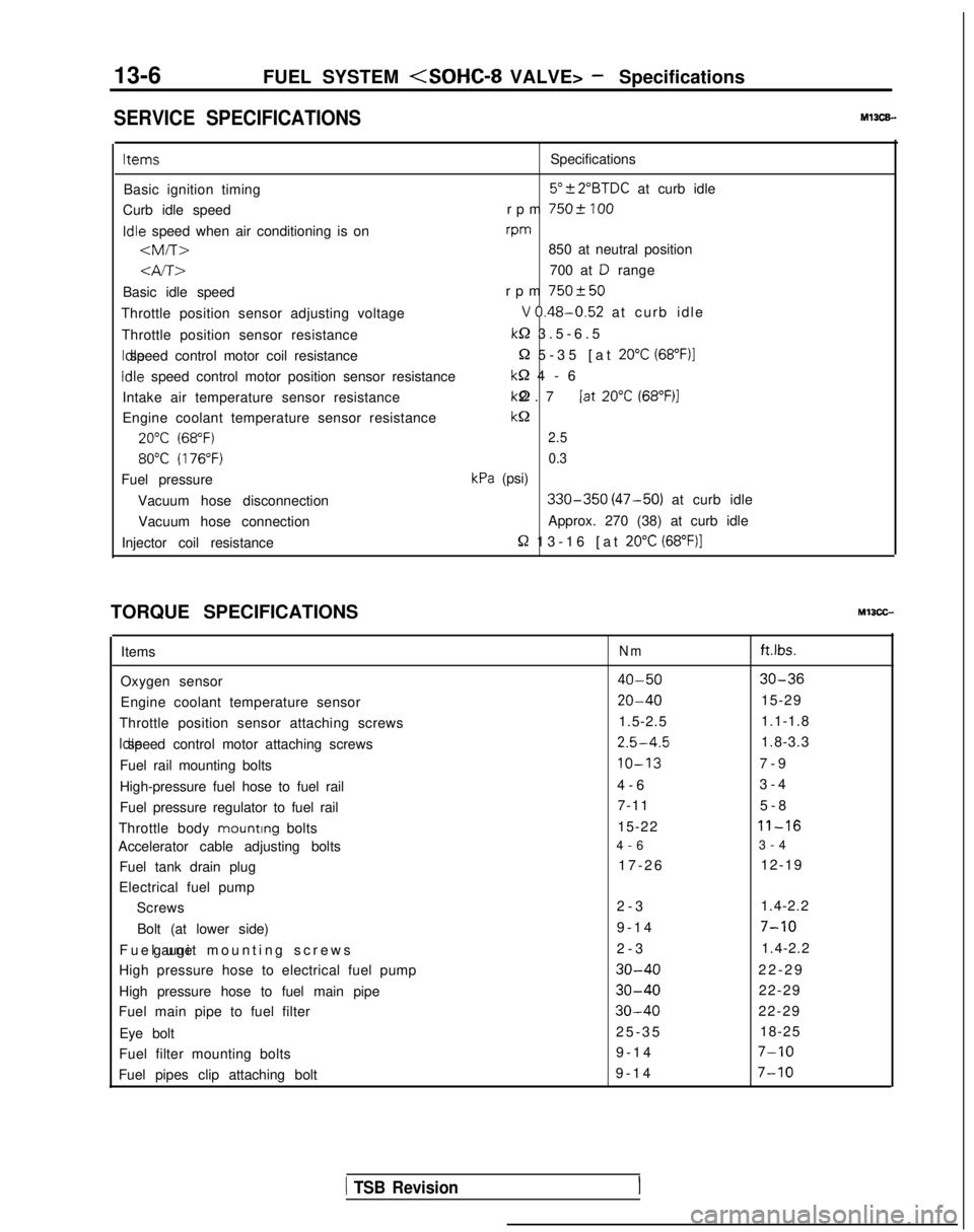
FUEL SYSTEM
SERVICE SPECIFICATIONSMl3CE.
ItemsSpecifications
Basic ignition timing
5”?2”BTDC at curb idle
Curb idle speed rpm
7502 100Idle
speed when air conditioning is on rpm
-am-r>850 at neutral position
4A>700 at D range
Basic idle speed rpm
750+50
Throttle position sensor adjusting voltageV 0.48-0.52 at curb idl
e
Throttle position sensor resistance
k-2 3.5-6.
5
Idle speed control motor coil resistance
Q 5-35 [at 20°C (68”F)l
Idle
speed control motor position sensor resistance
M-2 4-
6
Intake air temperature sensor resistance kQ 2.7 [at
20°C (68”F)l
Engine coolant temperature sensor resistancekc2
20°C (68°F)2.5
80°C (176°F)0.3
Fuel pressurekPa (psi)
Vacuum hose disconnection
330-350 (47-50) at curb idle
Vacuum hose connection Approx. 270 (38) at curb idle
Injector coil resistance
R 13-16 [at 20°C (68”F)]
TORQUE SPECIFICATIONSMIICC-
Items
Oxygen sensor
Engine coolant temperature sensor
Throttle position sensor attaching screws Idle speed control motor attaching screws
Fuel rail mounting bolts
High-pressure fuel hose to fuel rail
Fuel pressure regulator to fuel rail
Throttle body mounting
bolts
Accelerator cable adjusting bolts
Fuel tank drain plug
Electrical fuel pump Screws
Bolt (at lower side)
Fuel unit mounting screws gauge
High pressure hose to electrical fuel pump
High pressure hose to fuel main pipe
Fuel main pipe to fuel filter
Eye bolt
Fuel filter mounting bolts
Fuel pipes clip attaching boltNmft.lbs.
40-5030-36
20-4015-29
1.5-2.5 1.1-1.8
2.5-4.51.8-3.3
IO-137-
9
4-6 3-4
7-11 5-8
15-22
11-16
4-
6
3-4
17-26 12-19
2-3 1.4-2.2
9-14
7-10
2-
3
1.4-2.2
30-4022-2
9
30-4022-29
30-4022-29
25-3
5
18-25
9-14
7-10
9-1
4
7-10
1 TSB Revision
Page 253 of 1273
FUEL SYSTEM
03R0297
Vapor hose
mmin.)Fillerhose
i2.l
B
3FOO7
A
1
Flare nut
Skure side
03Yo43
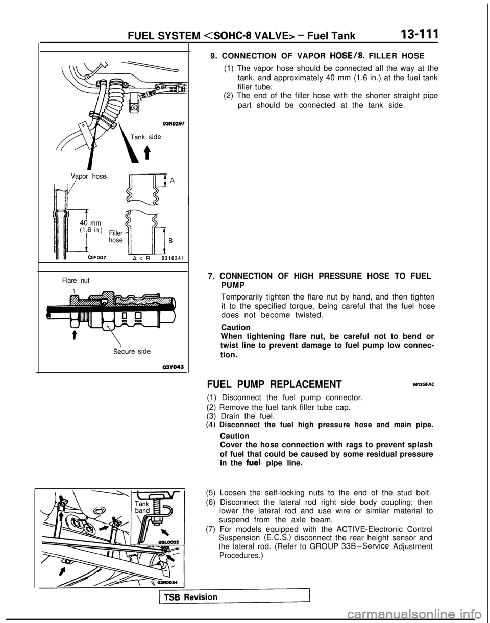
9. CONNECTION OF VAPOR HOSE/8. FILLER HOSE
(1) The vapor hose should be connected all the way at the tank, and approximately 40 mm (1.6 in.) at the fuel tank
filler tube.
(2) The end of the filler hose with the shorter straight pipe
part should be connected at the tank side.
7. CONNECTION OF HIGH PRESSURE HOSE TO FUEL PUMP
Temporarily tighten the flare nut by hand, and then tightenit to the specified torque, being careful that the fuel hose
does not become twisted.
Caution
When tightening flare nut, be careful not to bend or
twist line to prevent damage to fuel pump low connec-
tion.
FUEL PUMP REPLACEMENT
(1) Disconnect the fuel pump connector.
(2) Remove the fuel tank filler tube cap.
(3) Drain the fuel. MllGFAC
(4)
Disconnect the fuel high pressure hose and main pipe.
Caution
Cover the hose connection with rags to prevent splash
of fuel that could be caused by some residual pressure in the
fuel. pipe line.
(5) Loosen the self-locking nuts to the end of the stud bolt.
(6) Disconnect the lateral rod right side body coupling; then lower the lateral rod and use wire or similar material to
suspend from the axle beam.
(7) For models equipped with the ACTIVE-Electronic Control Suspension
(E.C.S.) disconnect the rear height sensor and
the lateral rod. (Refer to GROUP
33B-Service Adjustment
Procedures.)
Page 345 of 1273
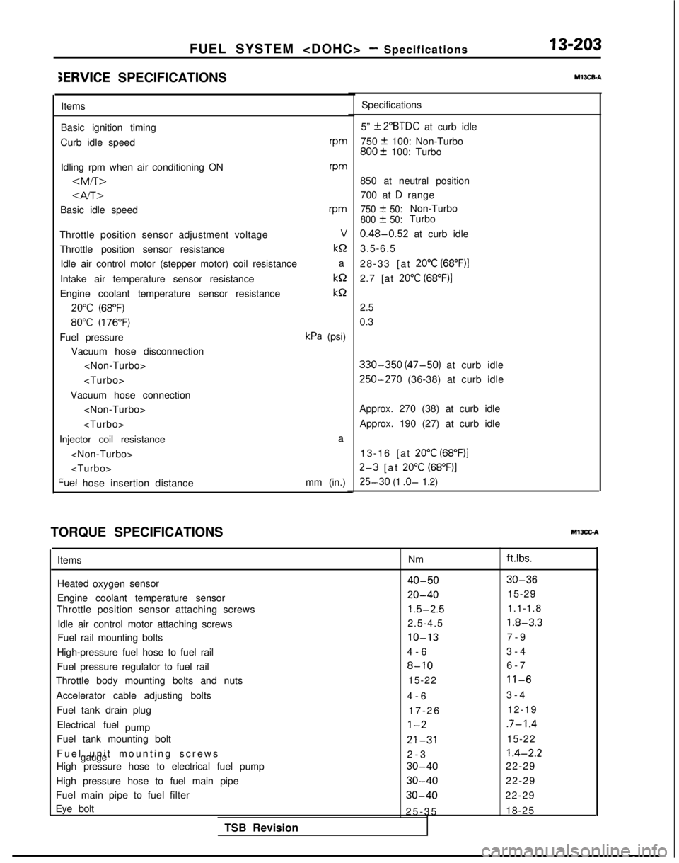
FUEL SYSTEM
iERVlCE SPECIFICATIONS
Items
Basic ignition timing
Curb idle speed rpm
Idling rpm when air conditioning ON
vm
Basic idle speedrm
Throttle position sensor adjustment voltageV
Throttle position sensor resistance kQ
Idle air control motor (stepper motor) coil resistance a
Intake air temperature sensor resistance kQ
Engine coolant temperature sensor resistance
kS2
20°C (68°F)
80°C (176°F)
Fuel pressurekPa (psi)
Vacuum hose disconnection
Vacuum hose connection
Injector coil resistance a
Qel hose insertion distance mm (in.)
TORQUE SPECIFICATIONS
Ml3CGA
m13caA
Specifications
5”
f 2”BTDC at curb idle
750
+ 100: Non-Turbo800? 100: Turbo
850 at neutral position 700 at
D range
750 & 50:Non-Turbo800 + 50:Turbo
0.48-0.52 at curb idle
3.5-6.5
28-33 [at
20°C (68”F)l
2.7 [at 20°C (68”F)j
2.5
0.3
330-350 (47-50) at curb idle
250-270 (36-38) at curb idle
Approx. 270 (38) at curb idle Approx. 190 (27) at curb idle
13-16 [at
20°C (68”F)]
2-3 [at 20°C (68”F)]
25-30 (1 .o- 1.2)
Items
Heated sensor oxygen
Engine coolant temperature sensor
Throttle position sensor attaching screws
Idle air control motor attaching screws
Fuel rail mounting bolts
High-pressure fuel hose to fuel rail
Fuel pressure regulator to fuel rail
Throttle body mounting bolts and nuts
Accelerator cable adjusting bolts Fuel tank drain plugElectrical fuel pump
Fuel tank mounting bolt
Fuel unit mounting screw
s
gaugeHigh pressure hose to electrical fuel pump
High pressure hose to fuel main pipe
Fuel main pipe to fuel filter
Eye bolt
TSB Revision Nm
ft.lbs.
40-5030-36
20-4015-29
1.5-2.51.1-1.8
2.5-4.5
1.8-3.3
IO-137-
9
4-6 3-4
8-106-
7
15-22
11-6
4-
6
3-4
17-26 12-19
1-2.7-1.4
21-3115-22
2-
3
1.4-2.2
30-4022-29
30-4022-29
30-4022-29
25-3
5
18-25
Page 462 of 1273
13-320FUEL SYSTEM
03RO297
V/apor hose
mmin.)
3FOO7
Filler
hoseB
A
\Secure side 03YO43
Ll
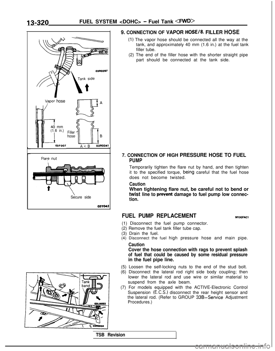
9. CONNECTION OF VAPOR HOSE/8. FILLER HOSE
(1) The vapor hose should be connected all the way at the
tank, and approximately 40 mm (1.6 in.) at the fuel tank
filler tube.
(2) The end of the filler hose with the shorter straight pipe part should be connected at the tank side.
7. CONNECTION OF HIGH PRESSURE HOSE TO FUEL
PUMP
Temporarily tighten the flare nut by hand, and then tighten
it to the specified torque,
bein,g careful that the fuel hose
does not become twisted.
Caution
When tightening flare nut, be careful not to bend or
twist line to prevent damage to fuel pump low connec-
tion.
FUEL PUMP REPLACEMENT
(1) Disconnect the fuel pump connector.
(2) Remove the fuel tank filler tube cap.
(3) Drain the fuel.
Ml3GFAt.X
(4) Disconnect the fuel high pressure hose and main pipe.
Caution
Cover the hose connection with rags to prevent splash
of fuel that could be caused by some residual pressure
in the fuel pipe line.
(5) Loosen the self-locking nuts to the end of the stud bolt.
(6) Disconnect the lateral rod right side body coupling; then
lower the lateral rod and use wire or similar material to
suspend from the axle beam.
(7) For models equipped with the ACTIVE-Electronic Control Suspension
(E.C.S.) disconnect the rear height sensor and
the lateral rod. (Refer to GROUP
33B-Service Adjustment
Procedures.)
TSB Revision