Page 580 of 1273
14-28COOLING - Water Hose and Water Pipe
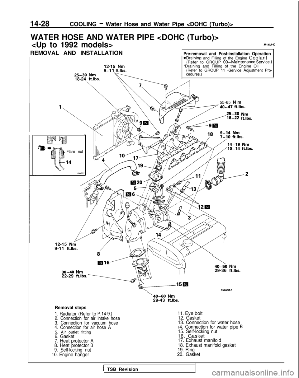
WATER HOSE AND WATER PIPE
Pre-removal and Post-installation Operation 1eDraining and Filling of the Engine Coolant
(Refer to GROUP 00-Maintenance Service.)
*Draining and Filling of the Engine Oil
(Refer to GROUP 11 -Service Adjustment Pro-
cedures.)
REMOVAL AND INSTALLATION
12-15 Nm
9-l 1 ft.lbs.25-30 Nm18-24 ft.lbs.
M141A-C
‘1
Flare nut 55-65
N
m
/-A 40-47 ft.lbs.
12-15 Nk9-11
ftlbs.
30-40 Nm
22-29 ft.lbs:
,“k.
Removal steps
I. Radiator (Refer to P.14-9.)2. Connection for air intake hose
3. Connection for vacuum hose
4. Connection for air hose A
5. Air outlet fitting6. Gasket
7. Heat protector A
8. Heat protector
B9. Self-locking nut10. Engine hanger
\40-50 Nm
29-36 ftlbs.
05Aoo54\40-60 Nm
29-43 ft.lbs.
II. Eye bolt12. Gasket
13. Connection for water hose
I 4. Connection for water pipe B15. Self-locking nut16. Gasket -17. Exhaust manifold
18. Exhaust manifold gasket
19. Ring
20. Gasket
i TSB Revision
Page 610 of 1273
15-24INTAKE AND EXHAUST - Turbocharger
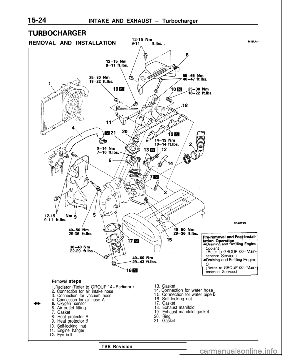
TURBOCHARGER
REMOVAL AND INSTALLATION12-15 Nm9-11 ft.lbs. )n
MlSLA-
40-47 ftlbs.
v I”12-15 Nm g
9-11 ftlbs.
i40-50 Nm29-36 ft.lbs.
05A0193
30-40 Nm22-29 ftlbs. *Draining
andRefilling Engine
(Refer to GROUPOO-Main-tenance Service.)aDraining and Refilling Engine
---. .- _^ . ._;_I(Refer to CiKUUi-’
UU-M~III-11
tenance Service.)-I
Removal steps
1.
Radiator (Refer to GROUP 14-Radiator.)
13. Gasket2. Connection for air intake hose14. Connection for water hose
3. Connection for vacuum hoseI 5. Connection for water pipe B
4. Connection for air hose A16. Self-locking nut
4*5.Oxygen sensor17.Gasket
6.Air outlet fitting18.Exhaust
manifold
7.Gasket19.Exhaustmanifold
gasket
8.Heat protector A 20.Ring
9.Heat protector B21.Gasket
10.Self-locking nut11.Engine hanger
12. Eye bolt
1‘
TSB RevisionI
Page 617 of 1273
INTAKE AND EXHAUST -Exhaust Manifold 15-31
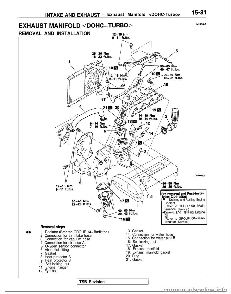
EXHAUST MANIFOLD
REMOVAL AND INSTALLATION
12-15
Nm
Removal
12-15.Nm - g-11
ft.lbs.
steps
9-l 1 ftlbs.
lh ./-I
‘Uc Ml5NA.C
05AO192
Coolant
(Refer to GROUP
00-Maimtenance Service.)eDraining and Refilling Engine
1. Radiator (Referto GROUP 14-Radiator.)
2. Connection for air intake hose
3. Connection for vacuum hose
4. Connection for air hose A 5. Oxygen sensor connector
6. Air outlet fitting
7. Gasket
8. Heat protector A 9. Heat protector
B10. Self-locking nut
11. Engine hanger
12. Eye bolt
‘\!I 1
5
Ilation Operationl Draining and Refilling Engine
Oil
-
(Refer to GROUP 00-Main.tenance Service.)
13. Gasket14. Connection for water hose15. Connection for water pipe.B16. Self-locking nut17. Gasket18. Exhaust manifold
19. Exhaust manifold gasket
20. Ring
21. Gasket
TSB Revision1
Page 666 of 1273
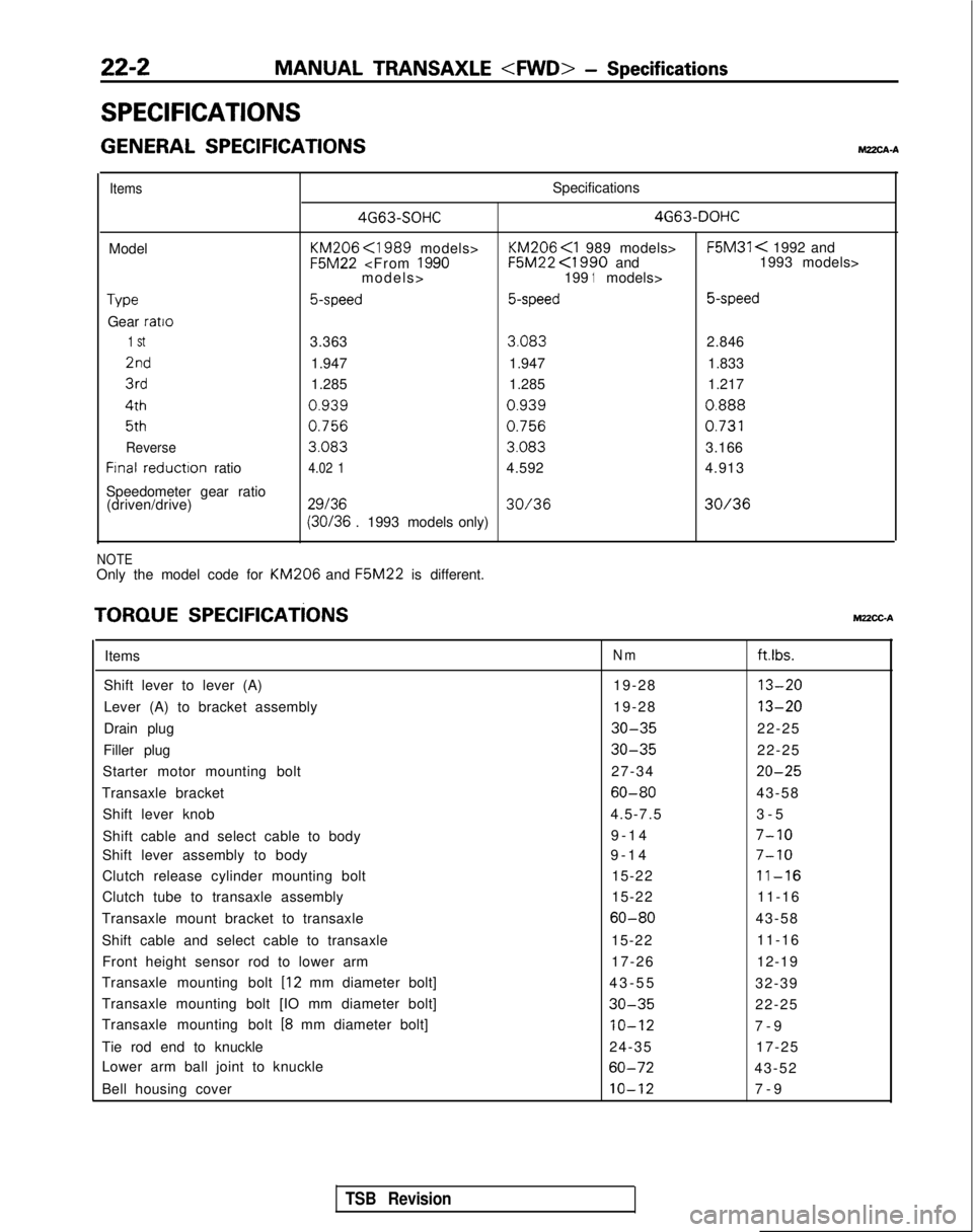
22-2MANUAL TRANSAXLE
- Specifications
SPECIFICATIONS
GENERAL SPECIFICATIONSMZXA-A
ItemsSpecifications 4G63-SOHC 4G63-DOHC
Model KM206
<1989 models> KM206
F5M31 < 1992 and F5M22
<1990 and 1993 models>
models> 1991models>
Type5-speed5-speed 5-speed
Gear ratio
1 St3.363
3.083
2.8462nd
1.947 1.947 1.8333rd
1.285 1.285 1.2174th
0.9390.9390.888
5th0.7560.756
0.731
Reverse
3.083 3.083
3.166
Frnal reductron
ratio4.02 14.592 4.913
Speedometer gear ratio (driven/drive)
2913630/3630/36 (30/36
. 1993 models only)
NOTEOnly the model code for KM206 and F5M22
is different.
TORQUE SPEClFlCATiONSMUCC-A
ItemsNmftlbs.
Shift lever to lever (A) 19-2813-20
Lever (A) to bracket assembly19-2813-20
Drain plug30-3522-25
Filler plug
30-3522-25
Starter motor mounting bolt 27-34
20-25
Transaxle bracket60-8043-58
Shift lever knob 4.5-7.53-
5
Shift cable and select cable to body 9-14
7-10
Shift lever assembly to body
9-1
4
7-10
Clutch release cylinder mounting bolt
15-2211-16
Clutch tube to transaxle assembly15-2211-16
Transaxle mount bracket to transaxle
60-8043-58
Shift cable and select cable to transaxle 15-2211-16
Front height sensor rod to lower arm 17-2612-19
Transaxle mounting bolt
[I2 mm diameter bolt] 43-5
5
32-39
Transaxle mounting bolt [IO mm diameter bolt]
30-3522-25
Transaxle mounting bolt
[8 mm diameter bolt]IO-127-
9
Tie rod end to knuckle 24-3517-25
Lower arm ball joint to knuckle
60-7243-52
Bell housing cover
10-127-
9
TSB Revision
Page 680 of 1273
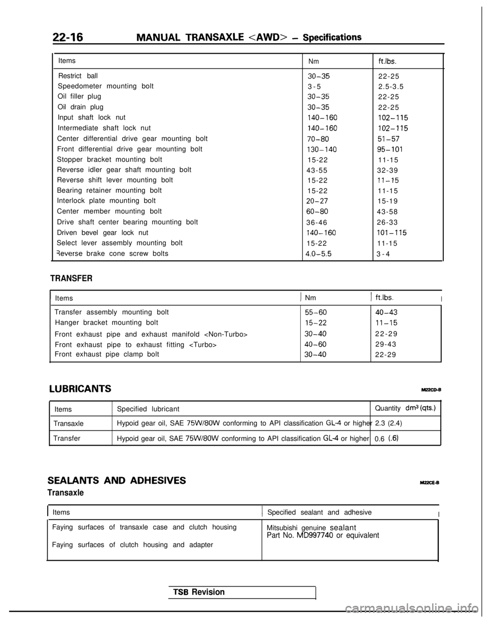
22-16MANUAL TRANSAXLE - Specifications
ItemsNmftlbs.
Restrict ball30-3522-25
Speedometer mounting bolt 3-
5
2.5-3.5
Oil filler plug
30-3522-25
Oil drain plug
30-3522-25
Input shaft lock nut
140-160102-115
Intermediate shaft lock nut140-160102-115
Center differential drive gear mounting bolt70-8051-57
Front differential drive gear mounting bolt130-14095-101
Stopper bracket mounting bolt 15-2211-15
Reverse idler gear shaft mounting bolt 43-5532-39
Reverse shift lever mounting bolt 15-22
71-15
Bearing retainer mounting bolt15-2211-15
Interlock plate mounting bolt
20-2715-19
Center member mounting bolt
60-8043-58
Drive shaft center bearing mounting bolt 36-4626-33
Driven bevel gear lock nut
740-160lOl-‘1’15
Select lever assembly mounting bolt 15-2211-15qeverse
brake cone screw bolts
4.0-5.53-
4
TRANSFER
1
Items
) Nm) ft.lbs.I
Transfer assembly mounting bolt55-6040-43
Hanger bracket mounting bolt15-2211-15
Front exhaust pipe and exhaust manifold 30-4022-2
9
Front exhaust pipe to exhaust fitting
40-6029-43
Front exhaust pipe clamp bolt
30-4022-29
LUBRICANTSMz2co-B
Items
Transaxle
Transfer Specified lubricant
Quantity drnj
(qts.)
Hypoid gear oil, SAE 75W/8OW conforming to API classification GL-4 or higher 2.3 (2.4)
Hypoid gear oil, SAE
75W/8OW conforming to API classification GL-4 or higher 0.6 t.6)
SEALANTS AND ADHESIVES
Transaxle
M22cE.B
IItems1 Specified sealant and adhesiveI
Faying surfaces of transaxle case and clutch housing
Mitsubishi genuine sealant
Part No. MD997740 or equivalent
Faying surfaces of clutch housing and adapter
TSB Revision
Page 726 of 1273
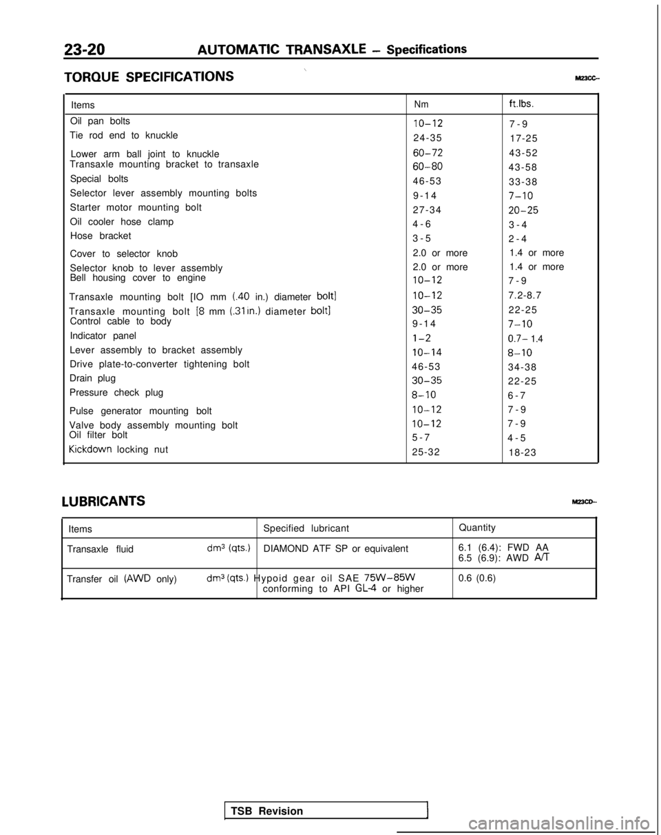
23-20AUTOMATIC TRANSAXLE
- Specifications
\TORQUE
SPECIFICATIONSMz3cc-
ItemsNmft.lbs.
Oil pan bolts10-127-
9
Tie rod end to knuckle 24-3517-25
Lower arm ball joint to knuckle
60-7243-52
Transaxle mounting bracket to transaxle
60-8043-58
Special bolts 46-5333-38
Selector lever assembly mounting bolts 9-1
4
7-10
Starter motor mounting bolt
27-3420-25
Oil cooler hose clamp4-
6
3-4
Hose bracket 3-52-4
Cover to selector knob 2.0 or more
1.4 or more
Selector knob to lever assembly 2.0 or more
1.4 or more
Bell housing cover to engine
10-127-
9
Transaxle mounting bolt [IO mm
(.40 in.) diameter bolt110-127.2-8.7
Transaxle mounting bolt
[8 mm (.31 In.) diameter bolt130-3522-25
Control cable to body 9-1
4
7-10
Indicator panell-20.7- 1.4
Lever assembly to bracket assembly10-148-10
Drive plate-to-converter tightening bolt
46-5334-38
Drain plug
30-3522-25
Pressure check plug
8-106-
7
Pulse generator mounting bolt
IO-127-
9
Valve body assembly mounting bolt
IO-127-
9
Oil filter bolt 5-74-5Kickdown
locking nut
25-3218-23LUBRICANTS
MPCD--
Items
Transaxle fluid Specified lubricant
Quantity
dm3 (qts.)DIAMOND ATF SP or equivalent6.1 (6.4): FWD AA
6.5 (6.9): AWD PJT
Transfer oil (AWD only)dm3 (qts.) Hypoid gear oil SAE 75W-85Wconforming to API GL-4 or higher0.6 (0.6)
TSB Revision
Page 807 of 1273
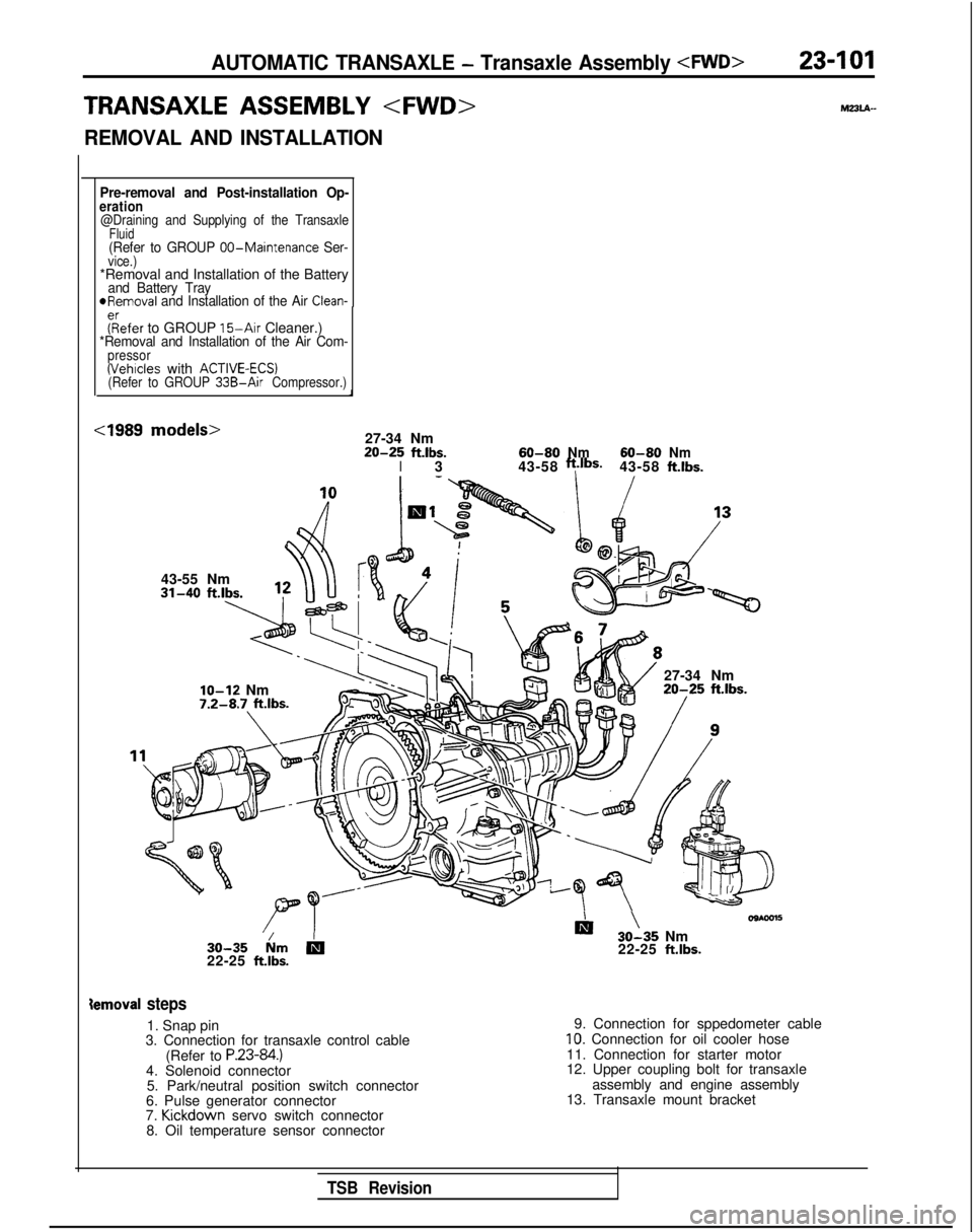
AUTOMATIC TRANSAXLE - Transaxle Assembly
TRANSAXLE ASSEMBLY
REMOVAL AND INSTALLATION
23-101
mz3u-
Pre-removal and Post-installation Op-eration@Draining and Supplying of the TransaxleFluid(Refer to GROUP 00-Maintenance Ser-vice.)*Removal and Installation of the Batteryand Battery TrayofRemoval and Installation of the Air Clean-
fRrefer to GROUP 15-Air
Cleaner.)*Removal and Installation of the Air Com-pressor(Vehicles with ACTIVE-ECS)(Refer to GROUP 33B-Air Compressor.)
cl989 models>27-34 Nm20-25ft.lbs.I360-80Nm43-58ft.lbS.60-80Nm43-58ft.lbs.
43-55 Nm
IO-12 Nm7.2-8.7 ft.lbs.
27-34 Nm20-25 ft.lbs.
30-35 km
b22-25 ft.lbs.
Iii ’30-35 Nm
22-25 ft.lbs.
ternoval steps
1. Snap pin
3. Connection for transaxle control cable
(Refer to
P.23-84.)4. Solenoid connector5. Park/neutral position switch connector
6. Pulse generator connector
7. Kickdown
servo switch connector
8. Oil temperature sensor connector 9. Connection for sppedometer cable
10. Connection for oil cooler hose
11. Connection for starter motor
12. Upper coupling bolt for transaxle assembly and engine assembly
13. Transaxle mount bracket
TSB Revision
Page 811 of 1273
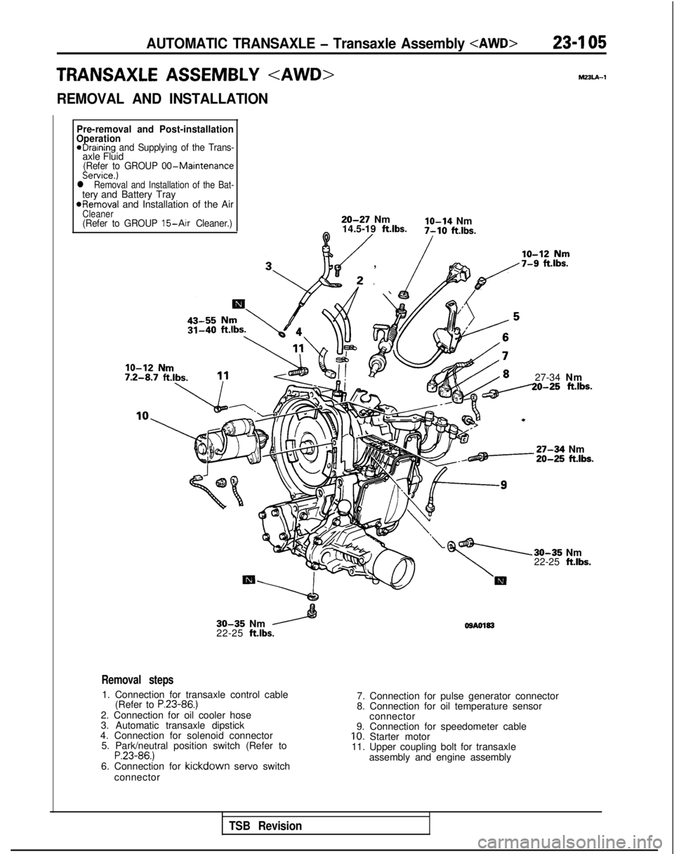
AUTOMATIC TRANSAXLE - Transaxle Assembly 23-I 05
TRANSAXLE ASSEMBLY hl33lA-1
REMOVAL AND INSTALLATION
Pre-removal and Post-installation
Operation
eDraining and Supplying of the Trans-axle Fluid(Refer to GROUP 00-MaintenanceService.)l Removal and Installation of the Bat-tery and Battery Tray
*Removal
and Installation of the Air
Cleaner(Refer to GROUP 15-Air Cleaner.)20-27 Nmlo-14 Nm
14.5-19 ft.lbs.0 /7-10 ft.lbs.
/
, \ fp,/7-9 f%.lbs.
27-34 Nm20-25 ft.lbs.
-27-34 Nm20-25 ft.lbs.
30-35 Nm
22-25 ft.lbs.
30-35 Nm
22-25 ft.lbs. OSA0183
Removal steps
1. Connection for transaxle control cable
(Refer to P.23-86.)2. Connection for oil cooler hose
3. Automatic transaxle dipstick
4. Connection for solenoid connector 5. Park/neutral position switch (Refer to
P.23-86.)6. Connection for kickdown servo switch
connector 7. Connection for pulse generator connector
8. Connection for oil temperature sensor
connector
9. Connection for speedometer cable
10. Starter motor
11. Upper coupling bolt for transaxle
assembly and engine assembly
TSB Revision