Page 871 of 1273
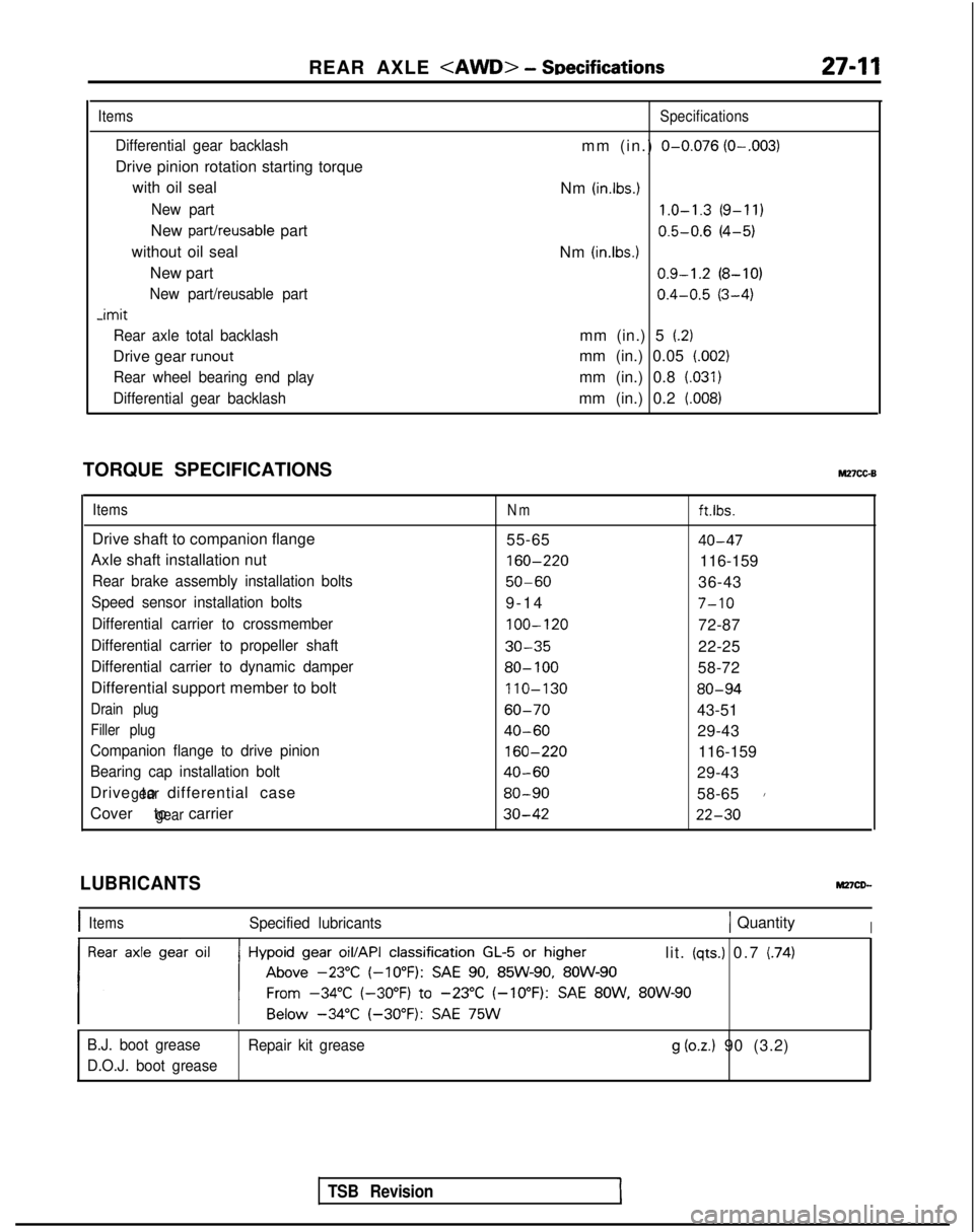
REAR AXLE - SDecifications27-11
Items
Differential gear backlash
Drive pinion rotation starting torque
with oil seal
New part
New part/reusable part
without oil seal New part
New part/reusable part -imit
Rear axle total backlash
Drive gear runout
Rear wheel bearing end play
Differential gear backlash
Specifications
mm (in.) O-0.076 (O-.003)
Nm (in.lbs.) 1.0-1.3
(9-11)
0.5-0.6
(4-5)
Nm
(in.lbs.1 0.9-1.2
(8-10)
0.4-0.5
(3-4)
mm (in.) 5
(2)
mm (in.) 0.05 (.002)
mm (in.) 0.8 (.031)
mm (in.) 0.2 (008)
TORQUE SPECIFICATIONSM27cc-B
ItemsNmft.lbs.
Drive shaft to companion flange 55-6540-47
Axle shaft installation nut 160-220
116-159
Rear brake assembly installation bolts50-6036-43
Speed sensor installation bolts9-1
4
7-10
Differential carrier to crossmember
100-120
72-87
Differential carrier to propeller shaft30-3522-25
Differential carrier to dynamic damper80- 10058-72
Differential support member to bolt 110-130
80-94
Drain plug60-7043-51
Filler plug40-6029-43
Companion flange to drive pinion
160-220
116-159
Bearing cap installation bolt40-6029-43
Drive to differential case
gear80-9058-651
Cover to carriergear30-4222-30
TSB Revision
LUBRICANTS
IItemsSpecified lubricants1 QuantityI
lit. (qts.) 0.7 (74)
B.J. boot grease Repair kit grease
g (oz.) 90 (3.2)
D.O.J. boot grease
Page 913 of 1273
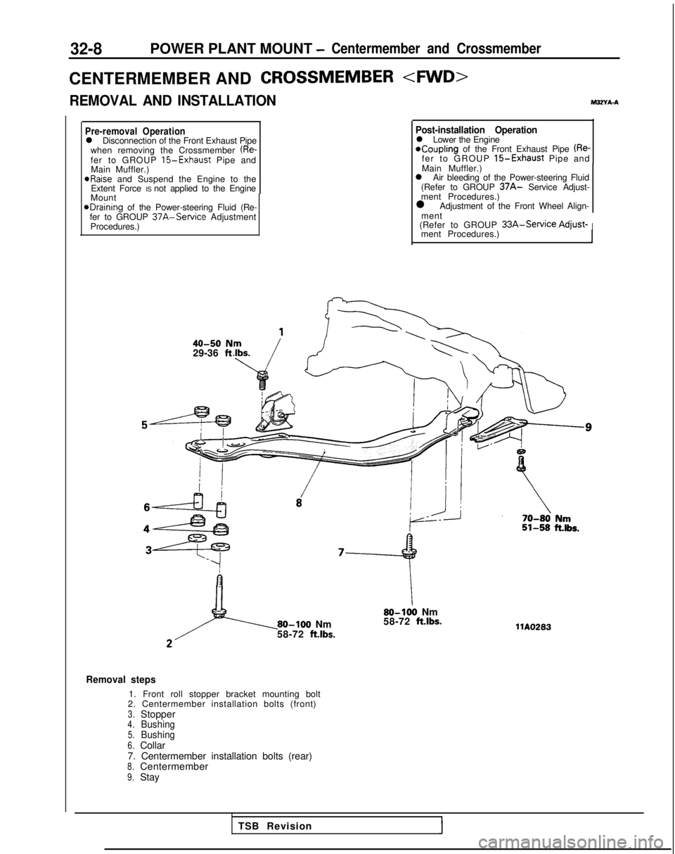
32-8POWER PLANT MOUNT -Centermember and Crossmember
CENTERMEMBER ANDCROSSMEMBER
REMOVAL AND INSTALLATIONM3ZYA-A
Pre-removal Operationl Disconnection of the Front Exhaust Pipe
when removing the Crossmember (Re-fer to GROUP 15-Exhaust Pipe and
Main Muffler.) aRaise
and Suspend the Engine to the
Extent Force IS not applied to the Engine
Mount
@Draining of the Power-steering Fluid (Re-
fer to GROUP 37A-Service Adjustment
Procedures.)
40-50 N29-36 ft
Post-installation Operationl Lower the Engine*Coupling of the Front Exhaust Pipe (Re-fer to GROUP 15-Exhaust Pipe and
Main Muffler.)
l Air bleeding of the Power-steering Fluid
(Refer to GROUP
37A- Service Adjust-
ment Procedures.)
l Adjustment of the Front Wheel Align-
ment
(Refer to GROUP
33A-Service Adjust-Iment Procedures.)
80-100 Nm
58-72 ft.lbs.
80-100 Nm
58-72 ft.lbs.
Removal steps
1. Front roll stopper bracket mounting bolt
2. Centermember installation bolts (front)
3.Stopper4.Bushing5.Bushing6.Collar
7. Centermember installation bolts (rear)
8.Centermember9.Stay llA0283
TSB Revision
Page 917 of 1273
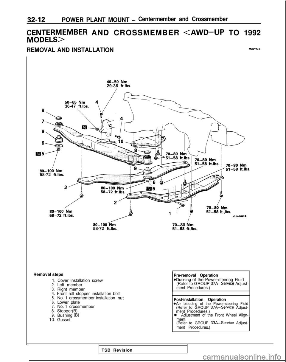
32-12POWER PLANT MOUNT -Centermember and Crossmember
C&Et;;rSM>EMBER AND CROSSMEMBER
REMOVAL AND INSTALLATIONM32Yh-0
40-50 Nm29-36 ft.lbs.
50-65 Nm36-47 ft.lbs.80-100
Nm58-72 ftlbs.
80-100
Nm58-72 ft.lbs.
1
’
--
--_ii-58 it.,tTlAO619I 70-r
80 km51-58klbs.
Removal steps
1. Cover installation screw
2.Left member3.Right member
4. Front roll stopper installation bolt
5.No. 1 crossmember installation
nut6.Lower plate7.No. 1 crossmember8.Stopper(B)9.Bushing (B)10.Gusset
Pre-removal OperationeDraining of the Power-steering Fluid
(Refer to GROUP 37A-Service
Adjust-
ment Procedures.)
Post-installation Operation@Air bleeding of the Power-steering Fluid
(Refer to GROUP 37A-Service Adjust-ment Procedures.)l Adjustment of the Front Wheel Align-
ment
(Refer to GROUP 33A-Service Adjust-ment Procedures.)
TSB Revision
Page 1206 of 1273
SERVICE BRAKES - Brake Booster35-85
BRAKE BOOSTER
REMOVAL AND INSTALLATION
MJSJA--
Pre-removal Operation
12@Draining of Brake Fluid
-!3\
Cl989 models> 6-9 ft.lbs. A 1
Post-installation Operation6upplying Brake Fulid*Bleeding (Refer to P.35-57.)l Adjustment of Brake Pedal(Refer to P.35-53.)15-18
Nrh ‘7II-13 ftlbs. :From
1990 models>
15-18 Nm 7II-13 ft.lbs.
Removal steps
1. Brake fluid level sensor connector
2. Brake tube
3. Master cylinder, hose, reservoir assembly +*
l +4. Vacuum hose5. Check valve
+* l +6. Vacuum hose with check valve7. Fitting
8. Cotter pin
9. Washer 10.
Clevis pi
n
11. Sealer
c*
12. Proportioning valve installation bolt
13. Brake tube (front left) installation bolt
14. Brake booster
14A05360
.a
QI1 II ;‘,:
4%14u0050
14Y626
Sealant: 3M ATD Part No.8663or equivalent
TSB Revision
Page 1242 of 1273
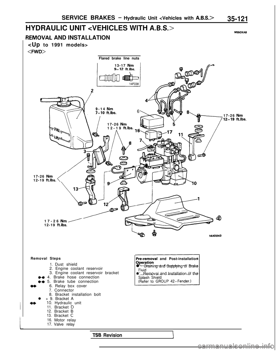
SERVICE BRAKES - Hydraulic Unit 35-121
HYDRAULIC UNIT hl35OXAB
L
IEMOVAL AND INSTALLATION
Flared brake line nuts
I13-17 NmA9- 12ftlbs.I@
9-14 Nm7-10
ft.lbs.6
i
17-26 Nm12-19
ft.lbs.
_ _
17-26 Nm/12-19 ft.lbs.
\
17-26 Nm /12-19 ft.lbs.
Removal Steps
1.Dust shield
2. Engine coolant reservoir
3. Engine coolant reservoir bracket
I)+ 4. Brake hose connectionI)+ 5. Brake tube connection
*I)6. Relay box cover7.Connector
8. Bracket installation bolt
l + 9. Bracket A
+*10. Hydraulic unit11.Bracket D
12.Bracket B13.Bracket C
16.
Motor relay17.Valve relay Pre-removal
and Post-installation
l Draining and Supplying of Brake
l Removai and Installation of the 17-26
Nm,12-19 ft.lbs.
TSB RevisionI
Page 1243 of 1273
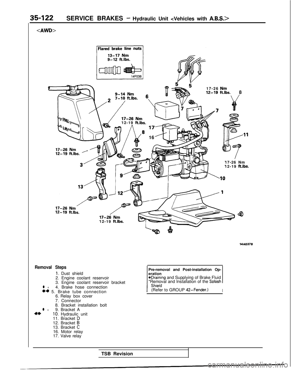
35-122SERVICE BRAKES - Hydraulic Unit
9-14 Nm
17-26 Nm12-19 ft.lbs.
8
17-26 Nm12-19 ft.lbs.
16
17-26 Nm
,
17-26 Nm
12-19 ft.lbs.
17-26
Nm12-19
ft.lbs.
12-19
ft.lbs.
Removal Steps
I. Dust shield
2. Engine coolant reservoir
l +3. Engine coolant reservoir bracket
4. Brake hose connection
W 5. Brake tube connection 6. Relay box cover
7. Connector
8. Bracket installation bolt
l +9. Bracket A4*IO. Hydraulic unit
11. Bracket D12. Bracket B13. Bracket C16. Motor relay
17. Valve relay Pre-removal and Post-installation Op-
eration
eDraining and Supplying of Brake Fluid
*Removal and Installation of the Solash
(Refer to GROUP 42-Fender.)I
TSB Revision
Page:
< prev 1-8 9-16 17-24