1989 MITSUBISHI GALANT brake light
[x] Cancel search: brake lightPage 47 of 1273
14KO24
OOA0186
GENERAL - Maintenance Service00-45
2.Inspect the wheel cylinder boots for evidence of a brake
fluid leak. Visually check the boots for cuts, tears or heat cracks. (A slight amount of fluid on the boot may
not be a leak, but may be preservative fluid used at
assembly.)
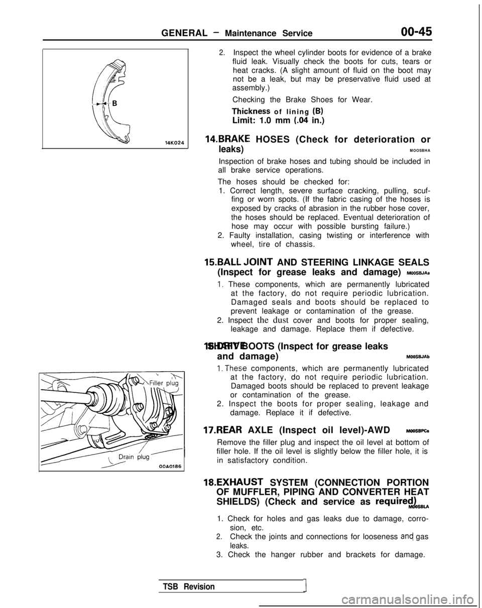
Checking the Brake Shoes for Wear. Thiclkness
of lining (B)
Limit: 1.0 mm
(.04 in.)
14.BRAKEI HOSES (Check for deterioration or
leaks)MOOSBHA
Inspection of brake hoses and tubing should be included in
all brake service operations.
The hoses should be checked for: 1. Correct length, severe surface cracking, pulling, scuf- fing or worn spots. (If the fabric casing of the hoses is
exposed by cracks of abrasion in the rubber hose cover,
the hoses should be replaced. Eventual deterioration of hose may occur with possible bursting failure.)
2. Faulty installation, casing twisting or interference with wheel, tire of chassis.
15.BALL ,IOINT AND STEERING LINKAGE SEALS
(Inspect for grease leaks and damage)
MOOSBJAa
I, These components, which are permanently lubricated at the factory, do not require periodic lubrication.Damaged seals and boots should be replaced to
prevent leakage or contamination of the grease.
2. Inspect the dust cover and boots for proper sealing, leakage and damage. Replace them if defective. 16.DRIVE SHAFT BOOTS (Inspect for grease leaks
and damage) MOOSWAb
1. The.se components, which are permanently lubricated
at the factory, do not require periodic lubrication.
Damaged boots should be replaced to prevent leakage
or contamination of the grease.
2. Inspect the boots for proper sealing, leakage and damage. Replace it if defective.
17.REAR AXLE (Inspect oil level)-AWD MOOSBPQ
Remove the filler plug and inspect the oil level at bottom of
filler hole. If the oil level is slightly below the filler hole, it is
in satisfactory condition. 18.EXHAIJST
SYSTEM (CONNECTION PORTION
OF MUFFLER, PIPING AND CONVERTER HEAT
SHIELDS) (Check and service as
require$LsBU
1. Check for holes and gas leaks due to damage, corro- sion, etc.
2.Check the joints and connections for looseness and gas
leaks.
3. Check the hanger rubber and brackets for damage.
TSB Revision1
Page 207 of 1273
FUEL SYSTEM
(1) Improper adjustment of the basic idling speed.
(2) Deposits adhering to the ttirottle valve.
(3) Air being taken into the intake manifold due to a gasket leak, etc.
OPERATION
ISC motor position sensor is a variable resistor type,
and is integrated in the
ISC motor system. The slid-
ing pin of
ISC motor position sensor is in contact
with the end of the plunger. Therefore, as the plun- ger moves, the internal resistance of
ISC motor pos-
ition sensor varies. This leads to the variation of the (4) Improper seating of the EGR valve seat.
(5) lmcomplete combustion within a cylinder. (Mal-
function of spark plugs, ignition coil, injectors,
compression pressure, etc.)
the plunger position of the
ISC motor system, and
sends the signal to ECM. ECM processes the
ISC
motor position sensor signal, idle signal, coolant
temperature signal, load signal (A/T &
A/C) and ve-
hicle speed signal to control the opening angle of
the throttle valve and revolution speed during
en-
output voltage. ISC motor position sensor detects gine idling.
TROUBLESHOOTING HINTS
Since idling is not controlled when ISC motor posi-
tion sensor is troubled, idling may not be evenly
maintained.
INSPECTION
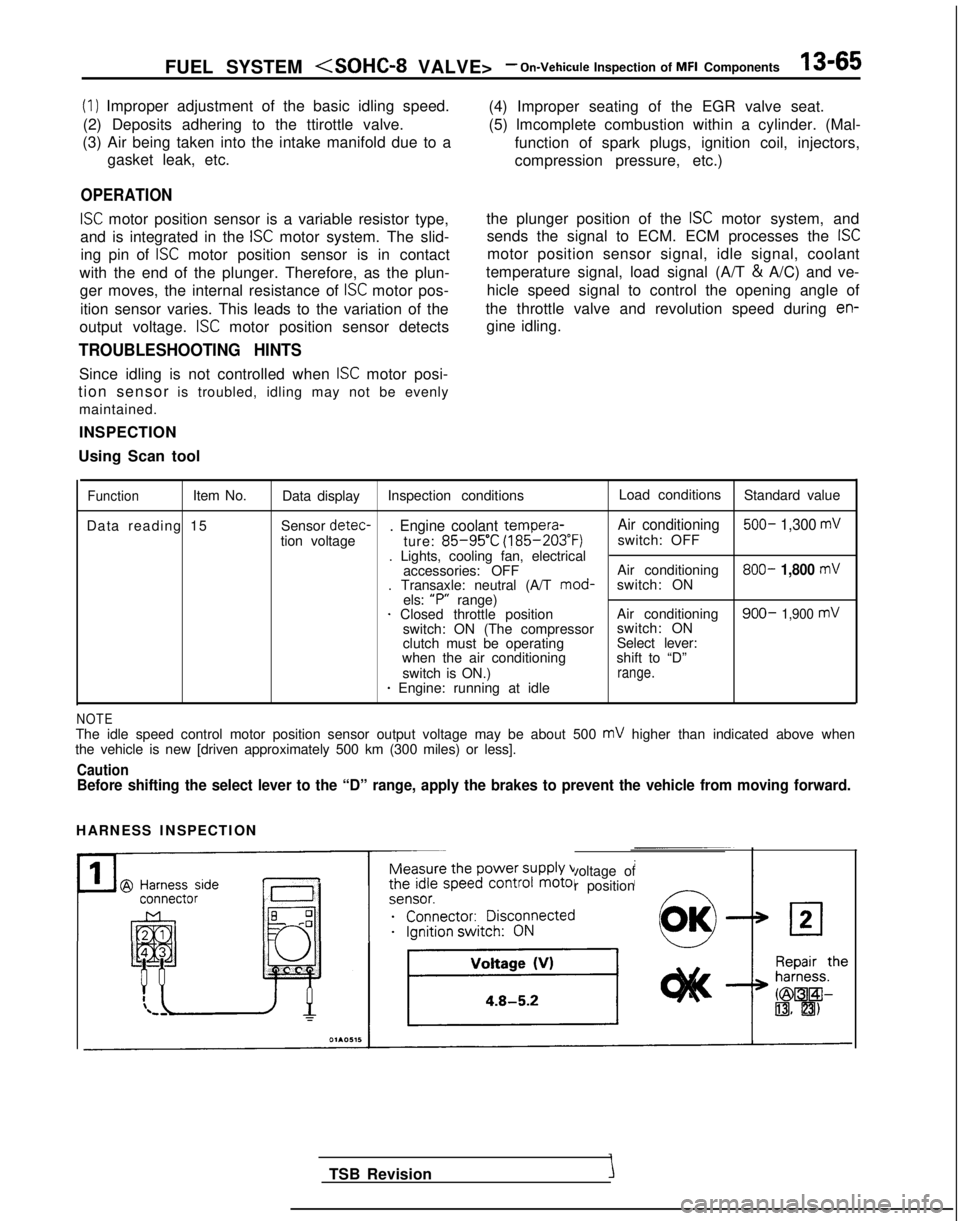
Using Scan tool
FunctionItem No. Data display Inspection conditions Load conditions
Standard value
Data reading 15 Sensor detec-
. Engine coolant tempera-
Air conditioning 500- 1,300 mV
tion voltage
ture: 85-95’C (185-203°F)
switch: OFF
. Lights, cooling fan, electrical accessories: OFF Air conditioning 800-
1,800 mV. Transaxle: neutral (A/T
mod-
switch: ON
els: “P”
range)
1 Closed throttle position Air conditioning900- 1,900 mVswitch: ON (The compressorswitch: ON
clutch must be operating Select lever:
when the air conditioning shift to “D”
switch is ON.)
range.* Engine: running at idle
NOTEThe idle speed control motor position sensor output voltage may be about\
500 mV higher than indicated above when
the vehicle is new [driven approximately 500 km (300 miles) or less].
CautionBefore shifting the select lever to the “D” range, apply the brake\
s to prevent the vehicle from moving forward.
HARNESS INSPECTION
Measure the power supply voltage of
the idle speed control motor position
ei;;;it;;sco$ected
__...._ -.-
TSB Revision
Page 305 of 1273
FUEL SYSTEM
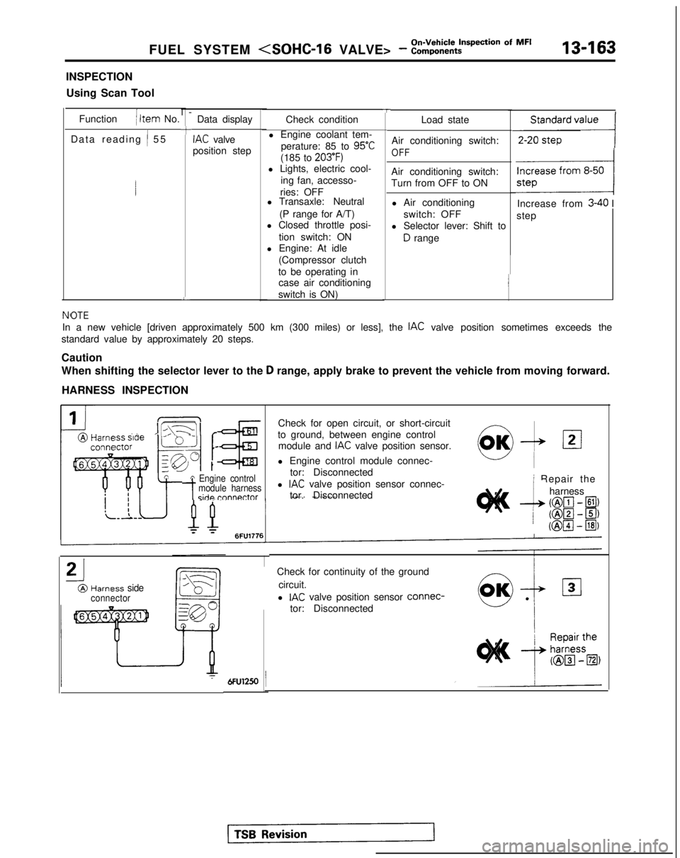
INSPECTION
Using Scan Tool
Function
( Item No.
Data reading
/ 5
5
l-
+
L
Data display
IAC valve
position step
TCheck condition
l Engine coolant tem- perature: 85 to
95°C
(185 to 203’F)l Lights, electric cool- ing fan, accesso-
ries: OFF
l Transaxle: Neutral
(P range for A/T)
l Closed throttle posi-
tion switch: ON
l Engine: At idle
(Compressor clutch
to be operating in case air conditioning
switch is ON) Load state
Air conditioning switch:
OFF
Air conditioning switch:
Turn from OFF to ON l Air conditioning switch: OFF
l Selector lever: Shift to
D range
,,,,,,,,,I
Increase from 3-40 I
step
NfOTE
In a new vehicle [driven approximately 500 km (300 miles) or less], th\
e IAC valve position sometimes exceeds the
standard value by approximately 20 steps.
Caution
When shifting the selector lever to the
D range, apply brake to prevent the vehicle from moving forward.
HARNESS INSPECTION
IIL\-11 r@Harm ” ’ -conna
tA Engine control
-tmodule harnessside rnnnnctor
Check for open circuit, or short-circuit
to ground, between engine control module and
IAC valve position sensor.
l Engine control module connec- tor: Disconnected
l
IAC valve position sensor connec-
tor. Disconnected
21
@Harness sideconnector
0,OK-& 121
i Repair the
--L
harness
(@lcl- El)
/ ml-~) (@pJ
- @I)
Check for continuity of the ground
circuit.
l
IAC valve position sensor connec-
tor: Disconnected
Page 478 of 1273
13-336AUTO-CRUISE CONTROL SYSTEM - Troubleshooting
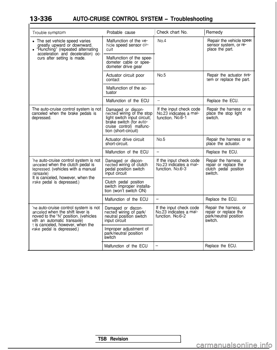
Probable cause1 Check chart No.1 Remedy
l The set vehicle speed variesMalfunction of the ve-No.4Repair the vehicle speec
greatly upward or downward.hicle speed sensor cir-sensor system, or re-l “Hunching” (repeated alternatingcuit place the part.
acceleration and deceleration) oc-
curs after setting is made.
Malfunction of the spee-dometer cable or spee-dometer drive gear
Actuator circuit poor
contact
Malfunction of the ac-
tuator
No.5Repair the actuator sys-tern or replace the part.
Malfunction of the ECU
-Replace the ECU.
The auto-cruise control system is notDamaged or discon-If the input check codeRepair the harness or re
canceled when the brake pedals isnetted wiring of the stopNo.23 indicates a mal- place the stop light
depressed.light switch input circuit; function. No.6-1switch.
brake switch (for auto-
cruise control) malfunc-
tion (short-circuit)
Actuator drive circuit
No.5Repair the harness or reshort-circuit.place the actuator.
Malfunction of the ECU
-Replace the ECU.
-he auto-cruise control system is notDamaged or discon-If the input check codeRepair the harness, or:anceled when the clutch pedal isnetted wiring of clutchNo.23 indicates a mal- repair or replace thedepressed. (vehicles with a manual pedal position switchfunction. No.6-3
clutch pedal position
ransaxle)input circuit switch.
It is canceled, however, when the
)rake pedal is depressed.) Clutch pedal positionswitch improper installa-
tion (won’t switch ON)
Malfunction of the ECU-Replace the ECU.
-he auto-cruise control system is notDamaged or discon-If the input check codeRepair the harness, orzanceled when the shift lever isnetted wiring of park/No.23 indicates a mal- repair or replace thenoved to the “N” position. (vehicles
neutral position switch function. No.6-2park/neutral positionvith an automatic transaxle)input circuit switch.t is canceled, however, when theIrake pedal is depressed.)Improper adjustment of
park/neutral position
switch
Malfunction of the ECU-Replace the ECU.
TSB Revision
Page 487 of 1273
AUTO-CRUISE CONTROL SYSTEM - Troubleshooting13-345
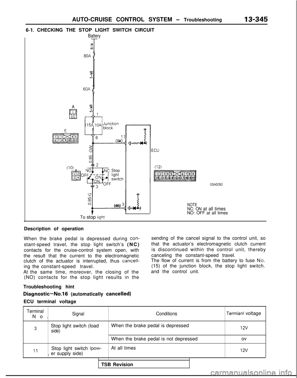
6-1. CHECKING THE STOP LIGHT SWITCH CIRCUIT
Battery
7Tco
A
9%6
I-
(GO) :
To stop light
NOTENC: ON at all timesNO: OFF at all times
Description of operation
When the brake pedal is depressed during
con-
stant-speed travel, the stop light switch’s (NC
)
contacts for the cruise-control system open, with
the result that the current to the electromagnetic
clutch of the actuator is interrupted, thus
cancell-
ing the constant-speed travel.
At the same time, moreover, the closing of the (NO) contacts for the stop light results in the
Troubleshooting hint sending of the cancel signal to the control unit, so
that the actuator’s electromagnetic clutch current is discontinued within the control unit, thereby
canceling the constant-speed travel.
The flow of current is from the battery to fuse N O.
(15) of the junction block, the stop light switch.
and the control unit.
Diagnostic-No.16 (automatically cancelled)
ECU terminal voltage
Terminal
No
.
SignalConditions
3Stop light switch (load
When the brake pedal is depressed
side)
When the brake pedal is not depressed
11Stop light switch (pow-At all times
, er supply side)
TSB Revision
Termianl voltage 12v
ov
12v
Page 493 of 1273
AUTO-CRUISE CONTROL SYSTEM - Troubleshooting
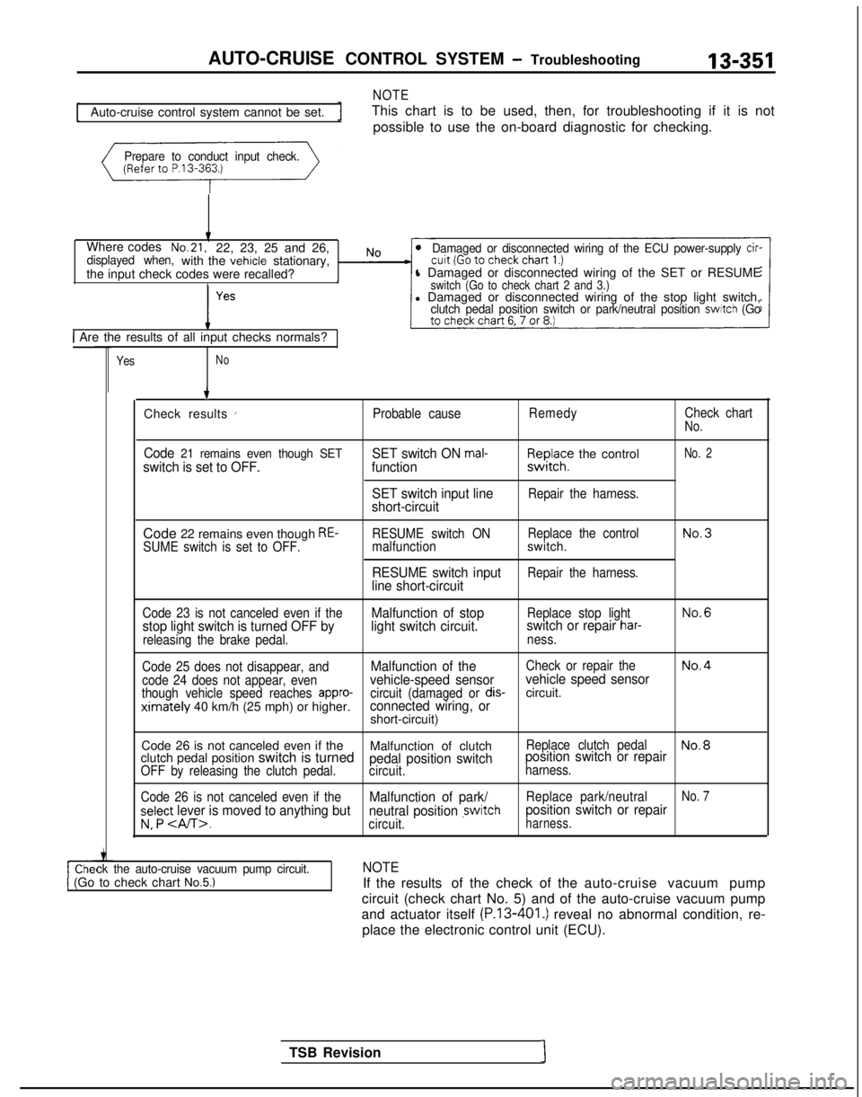
NOTE
13-351
Auto-cruise control system cannot be set.
This chart is to be used, then, for troubleshooting if it is not
possible to use the on-board diagnostic for checking.
Prepare to conduct input check.
Where codesNo.21,22, 23, 25 and 26,displayed when,with the vehicle stationary,
the input check codes were recalled?Damaged or disconnected wiring of the ECU power-supply cir-
l Damaged or disconnected wiring of the SET or RESUMEswitch (Go to check chart 2 and 3.)l Damaged or disconnected wiring of the stop light switch,clutch pedal position switch or park/neutral position switch (Go
1 Are the results of all input checks normals?
YesNo
ck the auto-cruise vacuum pump circuit.1 (Go to check chart No.5.)
TSB Revision1 7
Check results
’Probable cause RemedyCheck chartNo.
Code 21 remains even though SETswitch is set to OFF. SET switch ON mal-function
SET switch input line
short-circuitF,I~JI;? the control
Repair the harness.
No. 2
Code 22 remains even though RE-SUME switch is set to OFF. RESUME switch ON
Replace the controlNo.3malfunctionswitch.
RESUME switch inputRepair the harness.line short-circuit
Code 23 is not canceled even if theMalfunction of stopReplace stop lightNo.6
stop light switch is turned OFF by light switch circuit.switch or repair har-
releasing the brake pedal.
ness.
Code 25 does not disappear, and
Malfunction of theCheck or repair theNo.4
code 24 does not appear, evenvehicle-speed sensor vehicle speed sensorthough vehicle speed reaches appro-circuit (damaged or dis-circuit.ximately 40 km/h (25 mph) or higher.connected wiring, orshort-circuit)
Code 26 is not canceled even if the Malfunction of clutch
Replace clutch pedalNo.8clutch pedal position switch is turnedpedal position switchposition switch or repairOFF by releasing the clutch pedal.
circuit.harness.
Code 26 is not canceled even if the
Malfunction of park/Replace park/neutralNo. 7
select lever is moved to anything but neutral position ,switchposition switch or repair
v. P .circuit.harness.
NOTE
If the results of the check of the auto-cruise vacuum pump
circuit (check chart No. 5) and of the auto-cruise vacuum pump
and actuator itself
(P.13-401.) reveal no abnormal condition, re-
place the electronic control unit (ECU).
Page 494 of 1273
13-352AUTO-CRUISE CONTROL SYSTEM - Troubleshooting
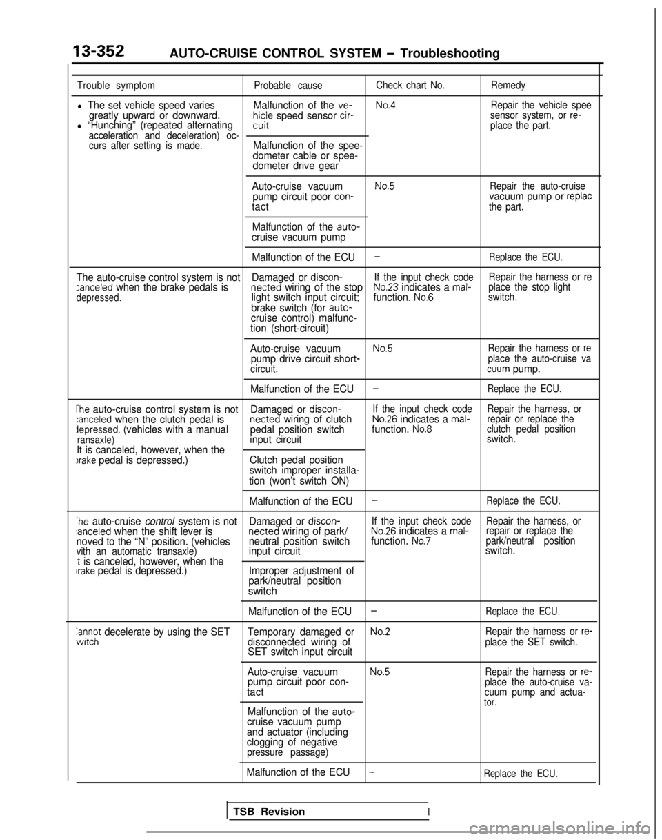
Trouble symptomProbable causeCheck chart No.
Remedy
l The set vehicle speed varies Malfunction of the ve-No.4Repair the vehicle speegreatly upward or downward.hicle speed sensor cir-l “Hunching” (repeated alternatingsensor system, or re-witplace the part.
acceleration and deceleration) oc- curs after setting is made.
Malfunction of the spee-
dometer cable or spee-
dometer drive gear
Auto-cruise vacuum
No.5Repair the auto-cruisepump circuit poor con-vacuum pump or replactactthe part.
Malfunction of the auto-cruise vacuum pump Malfunction of the ECU
-Replace the ECU.
The auto-cruise control system is not Damaged or discon-If the input check code Repair the harness or rezanceled when the brake pedals is netted wiring of the stopNo.23 indicates a mal-
depressed.light switch input circuit; function. No.6place the stop light
switch.
brake switch (for auto-cruise control) malfunc-
tion (short-circuit)
Auto-cruise vacuum
No.5Repair the harness or repump drive circuit short- place the auto-cruise va
circuit.cuum pump.
Malfunction of the ECU
-Replace the ECU.
The auto-cruise control system is not Damaged or discon-If the input check code
Repair the harness, or:anceled when the clutch pedal is netted wiring of clutchNo.26 indicates a mal-repair or replace thedepressed. (vehicles with a manual
pedal position switchfunction. No.8clutch pedal position
ransaxle)input circuitswitch.
It is canceled, however, when theIrake pedal is depressed.) Clutch pedal position
switch improper installa-
tion (won’t switch ON)
Malfunction of the ECU
-Replace the ECU.
*he auto-cruise control system is not Damaged or discon-If the input check code
Repair the harness, or:anceled when the shift lever is netted
wiring of park/No.26 indicates a mal-repair or replace the
noved to the “N” position. (vehicles neutral position switchfunction. No.7park/neutral position
vith an automatic transaxle)input circuit switch.t is canceled, however, when thebrake pedal is depressed.)
Improper adjustment of
park/neutral position
switch
Malfunction of the ECU-Replace the ECU.
anc$ decelerate by using the SET Temporary damaged orNo.2Repair the harness or re-disconnected wiring of
SET switch input circuitplace the SET switch.
Auto-cruise vacuumNo.5Repair the harness or re-pump circuit poor con-
tactplace the auto-cruise va-
cuum pump and actua-
tor.Malfunction of the auto-cruise vacuum pump
and actuator (including
clogging of negative
pressure passage)
Malfunction of the ECU-Replace the ECU.
TSB RevisionI
Page 499 of 1273
AUTO-CRUISE CONTROL SYSTEM - Troubleshooting
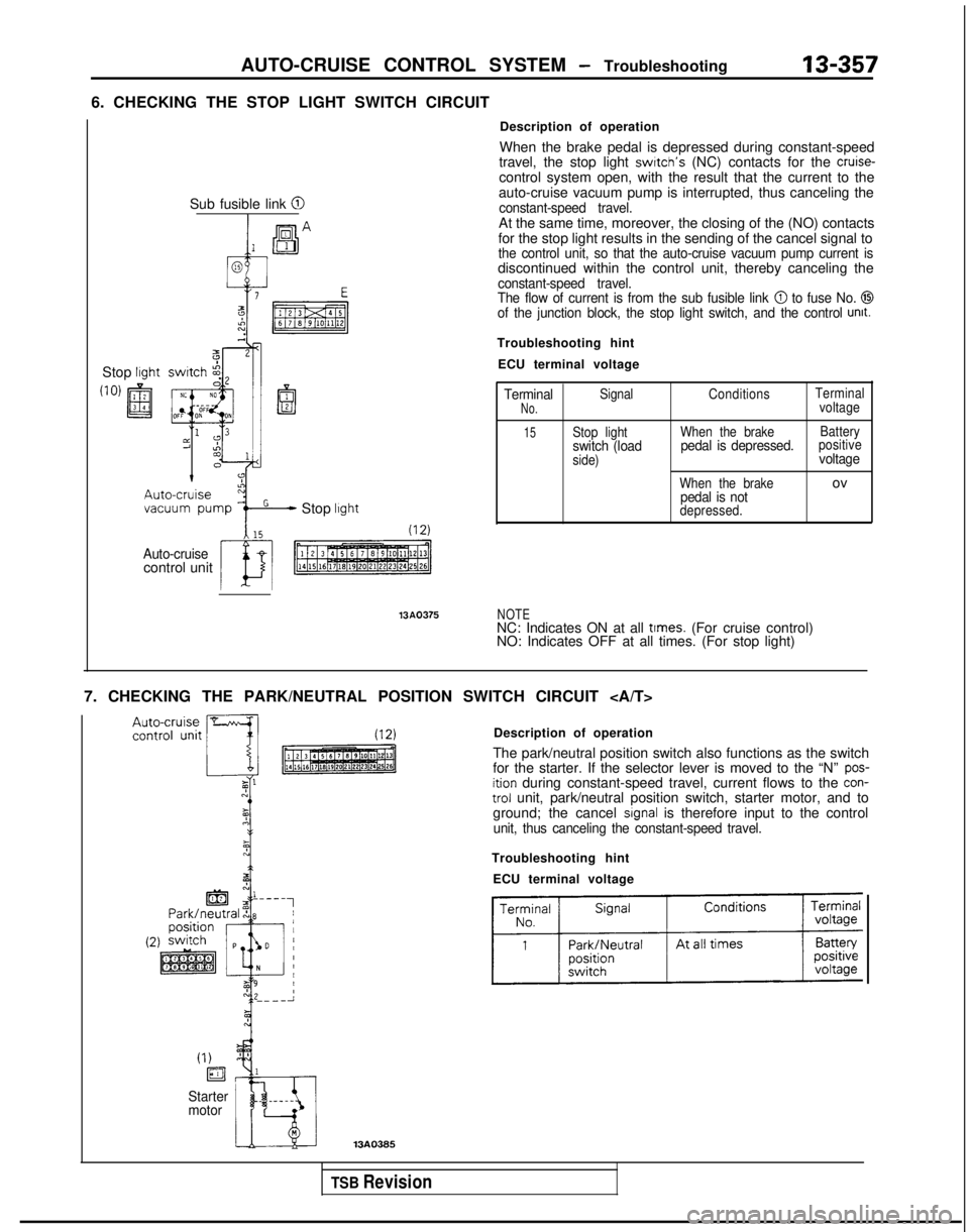
6. CHECKING THE STOP LIGHT SWITCH CIRCUIT13-357
Stop lrght
Sub fusible link @I
Stop lrght
Auto-cruisecontrol unit 13AQ375
Description of operation
When the brake pedal is depressed during constant-speed
travel, the stop light
swrtch’s (NC) contacts for the cruise-control system open, with the result that the current to the
auto-cruise vacuum pump is interrupted, thus canceling the
constant-speed travel.At the same time, moreover, the closing of the (NO) contacts
for the stop light results in the sending of the cancel signal to
the control unit, so that the auto-cruise vacuum pump current isdiscontinued within the control unit, thereby canceling theconstant-speed travel.
The flow of current is from the sub fusible link @ to fuse No. @Iof the junction block, the stop light switch, and the control unit.
Troubleshooting hint
ECU terminal voltage
TerminalSignal ConditionsTerminalNo.voltage
15Stop light
When the brake Batteryswitch (loadpedal is depressed.positive
side)voltage
When the brakeovpedal is notdepressed.
NOTENC: Indicates ON at all times. (For cruise control)
NO: Indicates OFF at all times. (For stop light)
7. CHECKING THE PARK/NEUTRAL POSITION SWITCH CIRCUIT Description of operation
The park/neutral position switch also functions as the switch
for the starter. If the selector lever is moved to the “N”
pos-ition during constant-speed travel, current flows to the con-trol unit, park/neutral position switch, starter motor, and to
ground; the cancel signal is therefore input to the controlunit, thus canceling the constant-speed travel.
Troubleshooting hint
ECU terminal voltage
(I)
ia
Starter
motor
TSB Revision