Page 837 of 1273
FRONT AXLE - Hub and Knuckle26-7
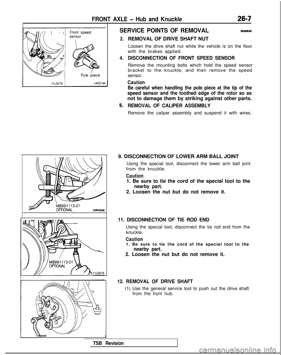
SERVICE POINTS OF REMOVALM261sAE
2.
4.
REMOVAL OF DRIVE SHAFT NUTLoosen the drive shaft nut while the vehicle is on the floor
with the brakes applied.
DISCONNECTION OF FRONT SPEED SENSOR
Remove the mounting bolts which hold the speed sensor
bracket to the knuckle, and then remove the speed
sensor.
Caution
Be careful when handling the pole piece at the tip of the
speed sensor and the toothed edge of the rotor so as
not to damage them by striking against other parts.
REMOVAL OF CALIPER ASSEMBLY
Remove the caliper assembly and suspend it with wires.
9. DISCONNECTION OF LOWER ARM BALL JOINT Using the special tool, disconnect the lower arm ball joint
from the knuckle.
Caution
1. Be sure to tie the cord of the special tool to the
nearby part.
2. Loosen the nut but do not remove it.
11. DISCONNECTION OF TIE ROD END
Using the special tool, disconnect the tie rod end from the
knuckle.
Caution
1. Be sure to tie the cord of the special tool to the
nearby part.
2. Loosen the nut but do not remove it.
12. REMOVAL OF DRIVE SHAFT
(1) Use the general service tool to push out the drive shaft from the front hub.
l\\11RO101 1
TSB Revision
Page 862 of 1273
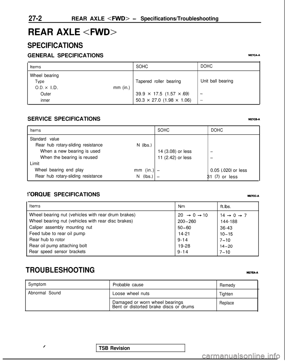
27-2REAR AXLE - Specifications/Troubleshooting
REAR AXLE
SPECIFICATIONS
GENERAL SPECIFICATIONSM2?CA-A
Items
Wheel bearing
Type
O.D. x I.D.
Outer
inner SOHC
DOHC
Tapered roller bearing
Unit ball bearing
mm (in.)
39.9 x 17.5 (1.57 x ,691-
50.3 x 27.0 (1.98 x 1.06)-
SERVICE SPECIFICATIONShl27CEA
Items
Standard value
Rear hub rotary-sliding resistance
When a new bearing is used
When the bearing is reused
Limit Wheel bearing end playRear hub rotary-sliding resistance
SOHC
N (Ibs.)
14 (3.08) or less
11 (2.42) or less
mm (in.)
-
N (Ibs.) -
DOHC
-
-
0.05 i.020) or less
31
(7) or less
1i-ORQUE SPECIFICATIONS MnCGA
Items
Wheel bearing nut (vehicles with rear drum brakes)
Wheel bearing nut (vehicles with rear disc brakes)
Caliper assembly mounting nut
Feed tube to rear oil pump
Rear hub to rotor
Rear oil pump attaching bolt
Rear speed sensor brackets
Nmft.lbs.
20 + 0 + IO14+0+7 200-260
144-188
50-6036-43
14-21
IO-15
9-147-10
19-2814-20
9-1
4
7-10
TROUBLESHOOTINGM27EA-A
Symptom
Abnormal SoundProbable cause
Loose wheel nuts
Damaged or worn wheel bearings
Bent or distorted brake discs or drums
Remedy
Tighten
Replace
TSB Revision
Page 868 of 1273
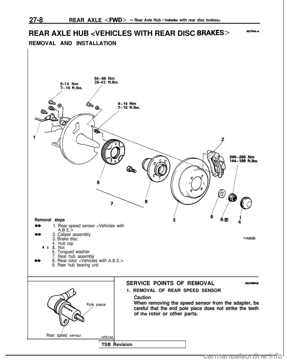
27-8REAR AXLE -4WD>- Rear Axle Hub
REAR AXLE HUB
REMOVAL AND INSTALLATION
M27MA-A
9-14 Nm7-10 ft.lbs.
50-60 Nm
36-43 ftlbs.
Removal steps
+*1. Rear speed sensor 4*2. Caliper assembly
3. Brake disc
I!jiEl 4
llA0030
4. Hub capl 45.
Nut6.Tonguedwasher
7. Rear hub assembly+*8. Rear rotor 9. Rear hub bearing unit
Rear speedsensor14ROlMI
SERVICE POINTS OF REMOVAL
1. REMOVAL OF REAR SPEED SENSOR
Caution
M27wBAB
When removing the speed sensor from the adapter, be
careful that the end pole piece does not strike the teeth
of the rotor or other parts.
TSB Revision
Page 869 of 1273
REAR AXLE - Rear Axle Hub
27-
9
2. REMOVAL OF CALIPER ASSEMBLY
Remove the caliper assembly and suspend it with a piece
of wire.
8. REMOVAL OF REAR ROTOR
Caution
Care must be taken not to scratch or otherwise damage
the teeth of the rotor. The rotor must never be dropped.
If the teeth of the rotor are chipped, resulting in a
deformation of the rotor, it will not be able to accurate- ly detect the wheel rotation speed, and the system will
not function normally.
INSPECTIONM27MFAAI
l Check the oil seal for crack or damage.
l
Check the surface of bearings for seizure, discoloration or
roughened raceway.
l Check the rear hub for wear or damage.
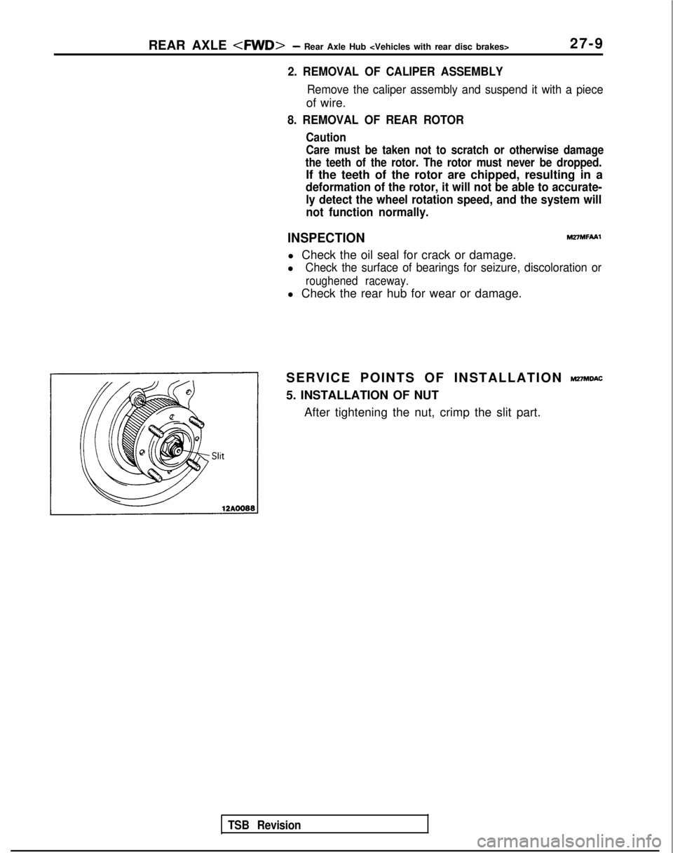
SERVICE POINTS OF INSTALLATION
MnMDAC
5. INSTALLATION OF NUT After tightening the nut, crimp the slit part.
TSB Revision
Page 877 of 1273
REAR AXLE - Axle Shaft27-17
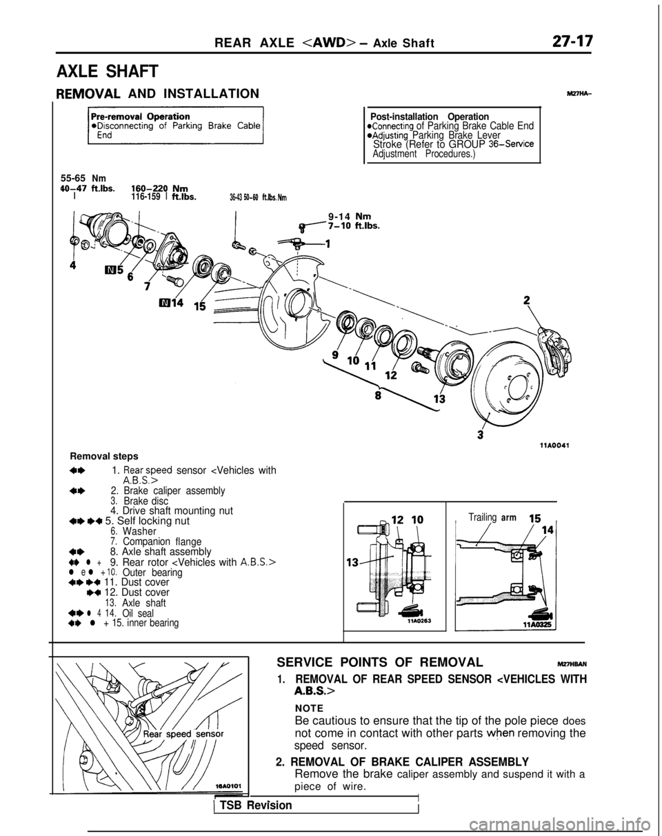
AXLE SHAFT
IEMOVAL
AND INSTALLATION
55-65
Nm 40-47
ftlbs.160-220NmI116-159
Ift.lbs.36-43 50-60ft.lbs. Nm
Post-installation OperationKonnecting of Parking Brake Cable End@Adjusting Parking Brake LeverStroke (Refer to GROUP 36-Service
Adjustment Procedures.)
9-14 Nmq------7-10 ft.lbs.
llA0041
Removal steps
4*1. ifsa.yyed sensor
4*2. Brake caliper assembly3.Brake disc4. Drive shaft mounting nut+I) e+ 5. Self locking nut6.Washer7.Companion flange4*8. Axle shaft assembly+e l +9. Rear rotor l e l + 10.Outer bearing+e ++ 11. Dust cover~~ 12. Dust cover13.Axle shaft4*l 414.Oil seal+e l + 15. inner bearing Trailing
arm 15
SERVICE POINTS OF REMOVAL
MmwAN
1.REMOVAL OF REAR SPEED SENSOR
A.B.S.>
NOTE
Be cautious to ensure that the tip of the pole piece does
not come in contact with other parts
when removing the
speed sensor.
2. REMOVAL OF BRAKE CALIPER ASSEMBLY
Remove the brake caliper assembly and suspend it with a
piece of wire.
I- _,1 TSB RevisionI
Page 1124 of 1273
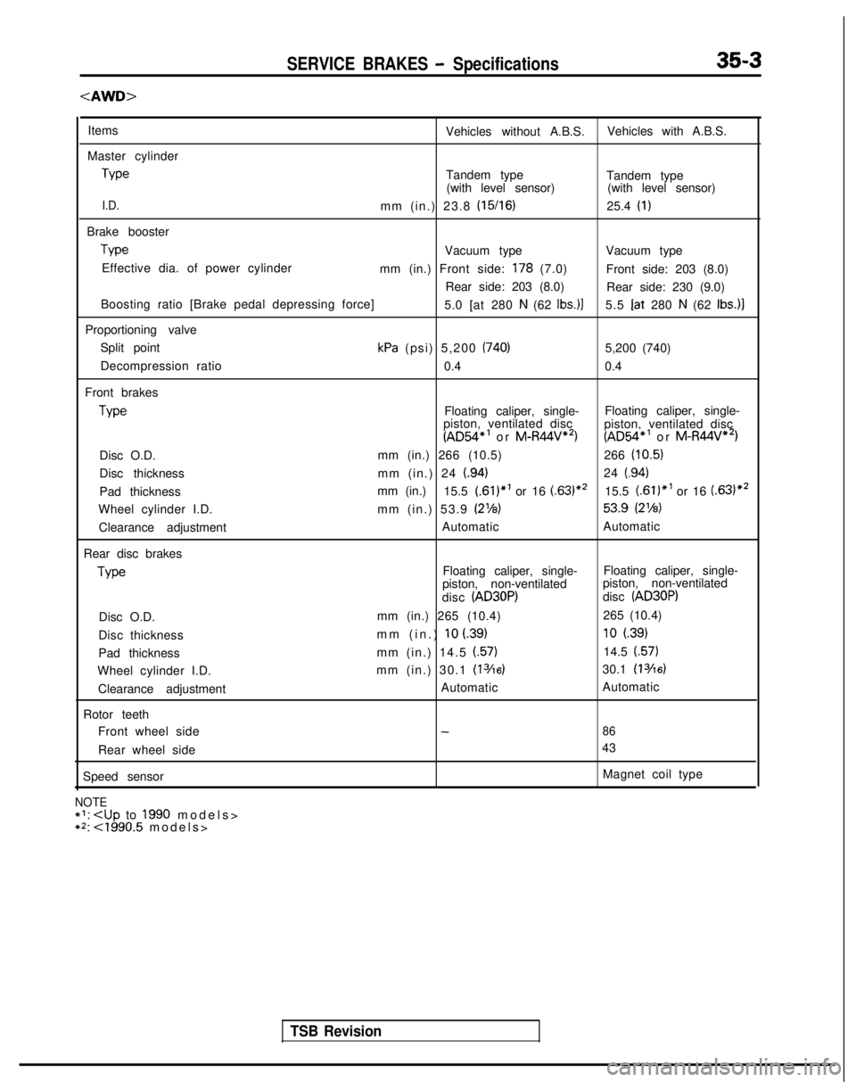
SERVICE BRAKES - Specifications35-3
Items
Vehicles without A.B.S.Vehicles with A.B.S.
Master cylinder Type
Tandem type
Tandem type
(with level sensor) (with level sensor)
I.D.mm (in.) 23.8 (15/16)25.4 (I)
Brake boosterType
Vacuum type
Vacuum type
Effective dia. of power cylinder mm (in.) Front side:
178 (7.0)Front side: 203 (8.0)
Rear side: 203 (8.0) Rear side: 230 (9.0)
Boosting ratio [Brake pedal depressing force] 5.0 [at 280
N (62 Ibs.)]5.5 Iat
280 N (62 Ibs.)]
Proportioning valve Split point
kPa (psi) 5,200 (740)5,200 (740)
Decompression ratio 0.40.4
Front brakes Type
Floating caliper, single-
Floating caliper, single-
piston, ventilated disc
(AD54”’ or M-R44V**)
piston, ventilated disc(AD54*’ or M-R44V**)
Disc O.D. mm (in.) 266 (10.5)
266
(10.5)
Disc thickness mm (in.) 24 (.94)24 (.94)
Pad thicknessmm (in.)
15.5 (.61)*’ or 16 (.63)*’15.5 f.61)“’ or 16 (.63)*2
Wheel cylinder I.D. mm (in.) 53.9 (2%) 53.9
(2%)
Clearance adjustment
Automatic
Automatic
Rear disc brakes Type
Floating caliper, single-
Floating caliper, single-
piston, non-ventilated piston, non-ventilated
disc
(AD30P)disc (AD30P)
Disc O.D. mm (in.) 265 (10.4)
265 (10.4)
Disc thickness mm (in.)
10 L39)10 (.39)
Pad thickness
mm (in.) 14.5 f.57)14.5 (.57)
Wheel cylinder I.D. mm (in.) 30.1 (13/16)30.1 (13/16)
Clearance adjustment Automatic
Automatic
Rotor teeth Front wheel side
-86
Rear wheel side 43
Speed sensor Magnet coil type
NOTE+‘:
>
**: <1990.5 models
>
TSB Revision
Page 1126 of 1273
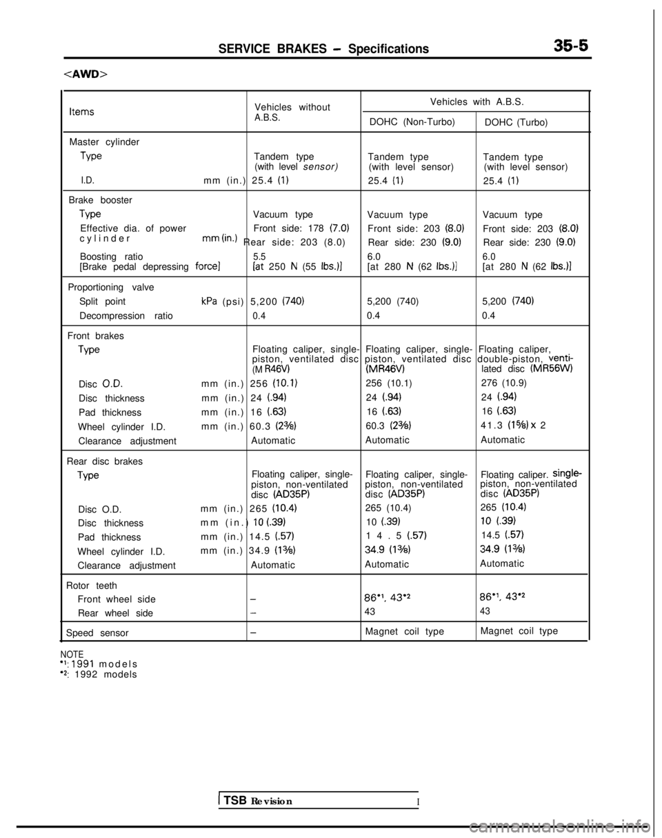
SERVICE BRAKES - Specifications35-5
Vehicles withoutVehicles with A.B.S.ItemsA.B.S.DOHC (Non-Turbo)
DOHC (Turbo)
Master cylinder Type
Tandem type
Tandem type Tandem type
(with level sensor) (with level sensor) (with level sensor)
I.D.mm (in.) 25.4 (1)25.4 (I)25.4 (I)
Brake boosterType
Vacuum type
Vacuum type Vacuum type
Effective dia. of power Front side: 178
(7.0)Front side: 203 (8.0)Front side: 203 (8.0)cylinde
r
mm
(in.) Rear side: 203 (8.0)
Rear side: 230 (9.0)Rear side: 230 (9.0)
Boosting ratio5.56.06.0[Brake pedal depressing force](at 250 N (55 Ibs.)][at 280 N (62 Ibs.)][at 280 N (62 Ibs.)l
Proportioning valve Split point
kPa (psi) 5,200 (740)5,200 (740) 5,200 (740)
Decompression ratio0.40.40.4
Front brakes Type
Floating caliper, single- Floating caliper, single- Floating caliper,
piston, ventilated disc piston, ventilated disc double-piston,
venti-(M R46V) (MR46V)
lated disc (MR56W)
Disc O.D.
mm (in.) 256
(10.1)256 (10.1)
276 (10.9)
Disc thickness mm (in.) 24
(.94)24 (.94)24 l.94)
Pad thickness mm (in.) 16
(.63)16 (.63)16 (63)
Wheel cylinder I.D. mm (in.) 60.3 (23/s)60.3 (23/8)41.3 (1%) x
2
Clearance adjustment AutomaticAutomatic
Automatic
Rear disc brakes Type
Floating caliper, single-
Floating caliper, single- Floating caliper.
Single-piston, non-ventilatedpiston, non-ventilated piston, non-ventilated
disc (AD35P)disc (AD35P)disc (AD35P)
Disc O.D. mm (in.) 265 (10.4)265 (10.4)
265 (10.4)
Disc thickness mm (in.) 10 (.39)10 l.39)10 l.39)
Pad thickness mm (in.) 14.5
(.57)14.5 (.57)14.5 (57)
Wheel cylinder I.D. mm (in.) 34.9 (13/8) 34.9
(13h) 34.9
(1%8)
Clearance adjustment AutomaticAutomatic Automatic
Rotor teeth Front wheel side
-86”. 43’286”‘. 43’2
Rear wheel side
-4343
Speed sensor-Magnet coil type Magnet coil type
NOTE+I: 1991 model
s
‘2: 1992 models
1 TSB RevisionI
Page 1128 of 1273
![MITSUBISHI GALANT 1989 Service Repair Manual SERVICE BRAKES - Specifications357
SERVICE SPECIFICATIONS [Up to 1990.5 models]
ItemsFWDAWD
Standard value Brake pedal height mm (in.) 176-181 (6.9-7.1)176-181
(6.9-7.1)
Brake pedal free play
mm (in.](/manual-img/19/57312/w960_57312-1127.png "MITSUBISHI GALANT 1989 Service Repair Manual SERVICE BRAKES - Specifications357
SERVICE SPECIFICATIONS [Up to 1990.5 models]
ItemsFWDAWD
Standard value Brake pedal height mm (in.) 176-181 (6.9-7.1)176-181
(6.9-7.1)
Brake pedal free play
mm (in.")
SERVICE BRAKES - Specifications357
SERVICE SPECIFICATIONS [Up to 1990.5 models]
ItemsFWDAWD
Standard value Brake pedal height mm (in.) 176-181 (6.9-7.1)176-181
(6.9-7.1)
Brake pedal free play
mm (in.) 3-8 (.I-.3)3-8 (.l-.3)
Brake pedal to floorboard clearancemm (in.) 80 (3.1) or more80 (3.1) or more
Proportioning valve pressure MPa (psi)
Split point 3.95-4.45 (561-633)
i.95-5.45 (704-775)
Output pressure [input pressure]
5.15-5.65 (732-804)*’ 6.55-7.05 (931-1,003)5.55-6.05 (789-861)“’ [9.2 (1.309)][8.2 (1,163)l
Booster push rod to master cylinder piston clearance mm (in.)
9 inch brake booster
0.8-1.0 (.031-,039) -
7 + 8 inch brake booster0.5-0.7 (.020-,028) -
8+9 inch brake booster0.6-0.8 (.024-,031)
Disc brake drag force (tangential force of wheel 70 (15.4) or less
70 (15.4) or less
mounting bolts)N (Ibs.)
Speed sensor’s internal resistance kB
0.8-I .2*30.8-I .2*3
Clearance between the speed pole piece and
0.3-0.9 (.012-.035)*30.3-0.9 (.Ol 2-.035)*3
the toothed rotor mm (in.)
-imit
Left/right proportioning valve output pressure difference
0.4 (57)0.4 (57) MPa
(psi)
Front disc runout
mm (in.) 0.10
(.0039) ‘1,*30.08 (.0031)
0.08(.0031) l 2
Pad thickness mm (in.) 2.0 (08)2.0 (08)
Front disc thicknessmm (in.) 22.4 (.882)22.4 (.882)
Rear disc thicknessmm (in.) 8.4 (.331)8.4 (331)
Rear disc runout
mm (in.) 0.08
(.0031)0.08 (0031)
Rear drum lining thickness mm (in.)
1.0 (04)
Rear drum inside diametermm (in.) 205 (8.1)-
NOTE~1: cl989 models
>
+2: <1990, 1990.5 models>*3: Vehicles with A.B.S.i
TSB Revision