1989 MITSUBISHI GALANT brake rotor
[x] Cancel search: brake rotorPage 1168 of 1273
SERVICE BRAKES - Anti-lock Braking System Troubleshooting35-47
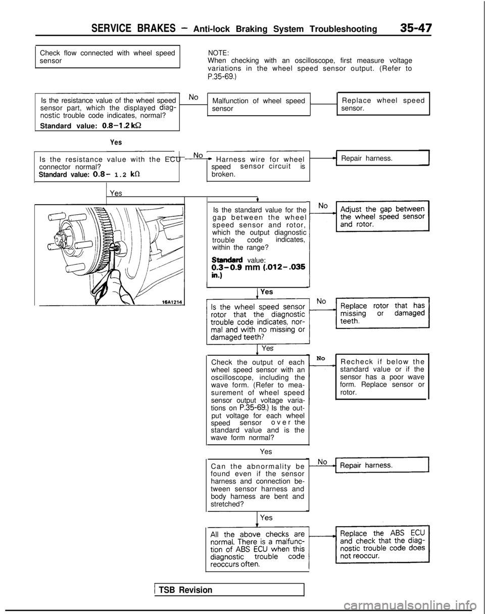
Check flow connected with wheel speed
sensorNOTE:When checking with an oscilloscope, first measure voltage
variations in the wheel speed sensor output. (Refer to
P.35-69.)
Is the resistance value of the wheel speedNoMalfunction of wheel speed . Replace wheel speed
sensor part, which the displayed diag-
sensor sensor.nostic
trouble code indicates, normal?
Standard value:
0.8-I .2 kSZ
Yes
Is the resistance value with the ECU No* Harness wire for wheel
connector normal? speedsensor circuitis
Standard value: 0.8- 1.2 k0broken.
I
Repair harness.
t
Is the standard value for the
gap between the whee
l
speed sensor and rotor,
which the output diagnostic
trouble codeindicates,
within the range?
stendllrd value:!I$0.9 mm (.012- .035
) YesI
1 Yes.
Check the output of each
wheel speed sensor with an
oscilloscope, including the
wave form. (Refer to mea-
surement of wheel speed
sensor output voltage varia-
tions on
P.35-69.) Is the out-
put voltage for each wheel
speed sensor over
thestandard value and is the
wave form normal?
Yes
Can the abnormality b
e
found even if the sensor
harness and connection be-
tween sensor harness and body harness are bent and
stretched? No
-Recheck if below th
e
standard value or if the
sensor has a poor wave
form. Replace sensor or
rotor.
1 TSB Revision
Page 1184 of 1273
SERVICE BRAKES - Service Adjustment Procedures35-63
(4) Calculate the drag torque of the disc brake (difference
between measured values in 3 and 4).
Standard value: 70 N (15.4 Ibs.) or less
10. If the disc brake drag force exceeds the standard value,
disassemble piston and clean the piston. Check for corro-
sion or worn piston seal, and check the sliding condition of
the lock pin and guide pin.
Front Disc Brake Rotor Inspection
CAUTION
When servicing disc brakes, it is necessary to exercise caution to keep \
the disc brakes within the allowable service values in order to maintain normal brake operation.
Before re-finishing or re-processing the brake disc surface, the followi\
ng conditions should be checked.
Inspection items
Scratches, rust, saturated lining materialsand wear
Run-out or drift
Change in thickness (parallelism) Inset or warping (flatness) Remarks
lIf the vehicle is not driven for a certain period, the sections of the d\
iscs
that are not in contact with lining will become rusty, causing noise and\
shuddering.
lIf grooves resulting from excessive disc wear and scratches are not re-
moved prior to installing a new pad assembly, there will momentarily
be inappropriate contact between the disc and the lining (pad).
Excessive run-out or drift of the discs will increase the pedal depressi\
on
resistance due to piston knock-back.
If the thickness of the disc changes, this will cause pedal pulsation, s\
hud-dering and surging.
Overheating and improper handling while servicing will cause inset orwarping.
RUN-OUT CHECKM35F5AB
1.Remove the caliper support; then raise the caliper assem-
bly upward and secure by using wire.
2.Inspect the disc surface for grooves, cracks, and rust. Clean
the disc throughly and remove all rust.
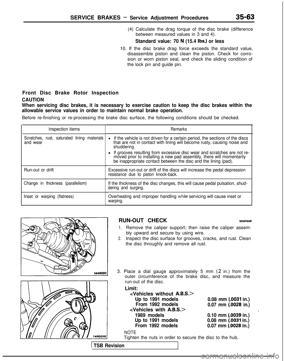
3. Place a dial gauge approximately 5 mm
(.2 in.) from the
outer circumference of the brake disc, and measure the
run-out of the disc.
Limit:
Up to 1991 models
0.08 mm (.0031 in.)
From 1992 models
0.07 mm (.0028 in.)
*1989 models
0.10 mm (.0039 in.)
Up to 1991 models 0.08 mm
(0031 in.)
From 1992 models 0.07 mm
(.0028 in.)
NOTE
Tighten the nuts in order to secure the disc to the hub.
1 TSB Revision
Page 1185 of 1273
35-64SERVICE BRAKES - Service Adjustment Procedures
RUN-OUT CORRECTIONM35FTAB
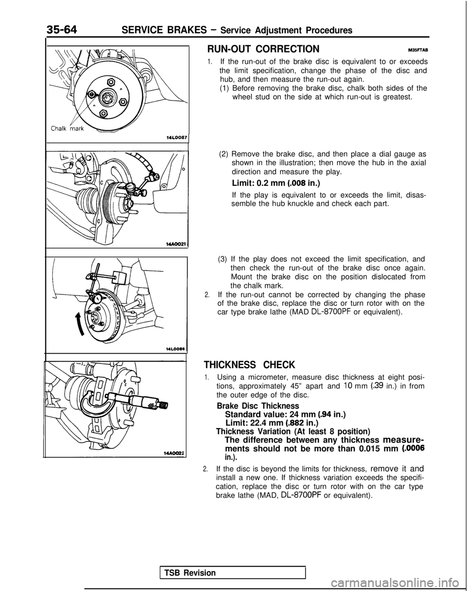
1.If the run-out of the brake disc is equivalent to or exceeds
the limit specification, change the phase of the disc and hub, and then measure the run-out again.
(1) Before removing the brake disc, chalk both sides of the wheel stud on the side at which run-out is greatest.
14LOOB7
(2) Remove the brake disc, and then place a dial gauge asshown in the illustration; then move the hub in the axial
direction and measure the play.
Limit: 0.2 mm
(.008 in.)
If the play is equivalent to or exceeds the limit, disas-
semble the hub knuckle and check each part.
(3) If the play does not exceed the limit specification, and then check the run-out of the brake disc once again.Mount the brake disc on the position dislocated from
the chalk mark.
2.If the run-out cannot be corrected by changing the phase
of the brake disc, replace the disc or turn rotor with on the
car type brake lathe (MAD
DL-8700PF or equivalent).
THICKNESS CHECK
1.Using a micrometer, measure disc thickness at eight posi-
tions, approximately 45” apart and
10 mm (.39 in.) in from
the outer edge of the disc.
Brake Disc Thickness
Standard value: 24 mm (.94 in.)
Limit: 22.4 mm
(.882 in.)
Thickness Variation (At least 8 position)
The difference between any thickness measure-
ments should not be more than 0.015 mm
(.OOOS
in.).
2.If the disc is beyond the limits for thickness, remove it and
install a new one. If thickness variation exceeds the specifi-
cation, replace the disc or turn rotor with on the car type brake lathe (MAD, DL-8700PF
or equivalent).
TSB Revision
Page 1190 of 1273
SERVICE BRAKES - Service Adjustment Procedures35-69
(5) The probable cause if the output voltage is 50 mV or lower, or if the one-side deflection width of the
oscilloscope’s waveform is 70
mV or lower
Probable causes Remedy
Excessive clearance between the speed sensor pole
piece and rotor Adjust to the standard value.
Foreign material attached to the speed sensor pole
pieceRemove the foreign material.
Damaged speed sensor pole pieceReplace the speed sensor.
Damaged rotor teeth~~~ rReplace the rotor.
Loose speed sensor or rotor installation bolt I
Tighten to the specified torque.
1
NOTE
The speed sensor internal resistance and harness side are normal.
Caution
It is conceivable, because the movement of a speed-sensor cable “foll\
ows” the movement of the front
or rear suspension, that the damaged wiring condition may be apparent on\
ly during travel on poor
road surfaces, and may be normal on better road surfaces. Therefore, whe\
n measuring the output
voltage of a speed sensor, recheck the condition of the cable connection\
s by removing the clamp and pulling the cable and bending it near the clamp position in order to che\
ck for the existence of damaged
wiring.
1/21314j51617)61Q~10~11~12)13~14~15)16~17~1~~19~20~21~22~23~24~25~26(27~26~2Q~30(31~32~33~34~35~
Check connector
74=f=n
ECU
*
Body harnessMB991 356fl 14N018C
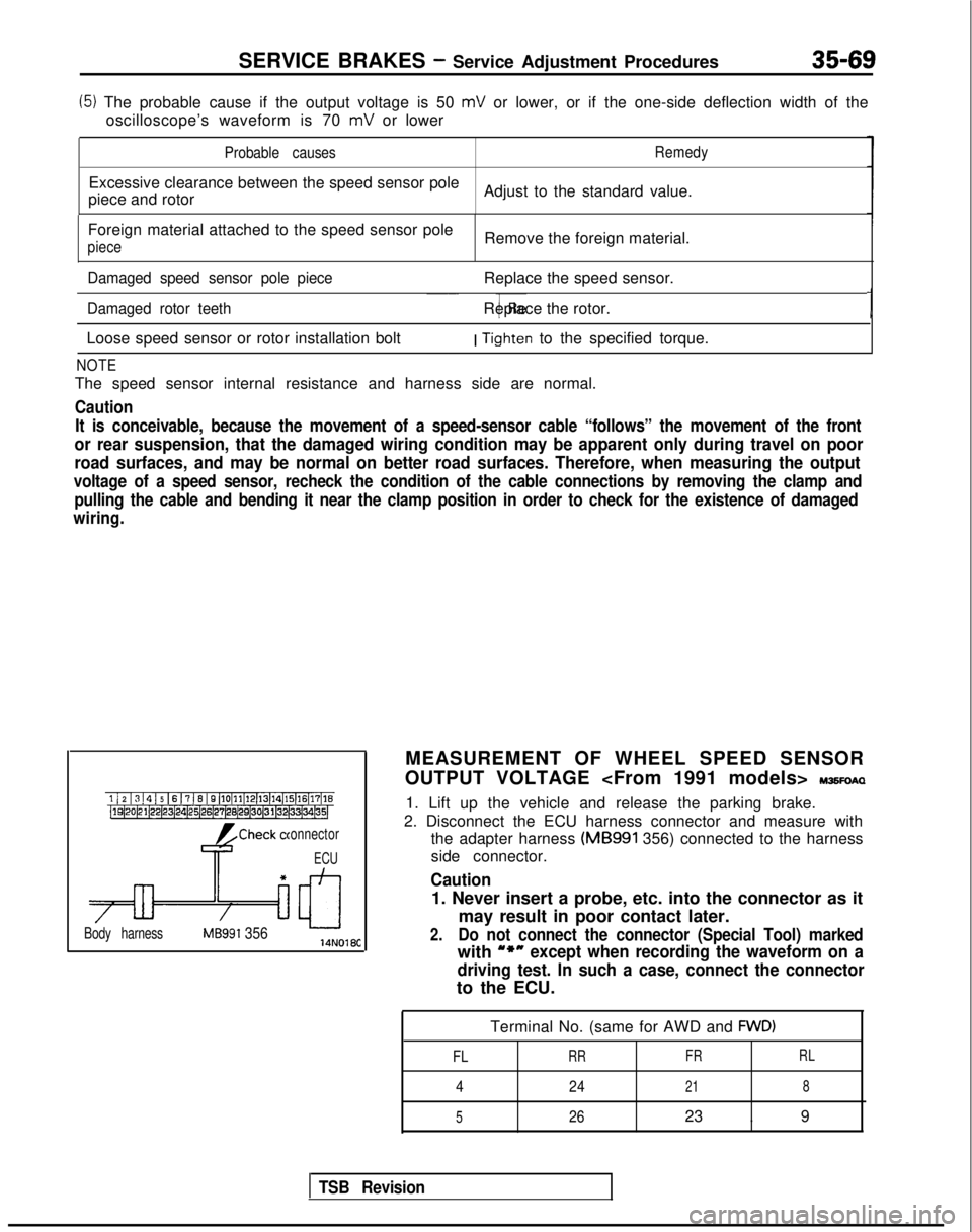
MEASUREMENT OF WHEEL SPEED SENSOR
OUTPUT VOLTAGE
IWSFOAQ
1. Lift up the vehicle and release the parking brake.
2. Disconnect the ECU harness connector and measure with the adapter harness (MB991
356) connected to the harness
side connector.
Caution
1. Never insert a probe, etc. into the connector as it
may result in poor contact later.
2.Do not connect the connector (Special Tool) marked
with u*nexcept when recording the waveform on a
driving test. In such a case, connect the connector
to the ECU.
Terminal No. (same for AWD and
FWD)
FL
RR FRRL
4
24218
5
2623 . 9
TSB Revision
Page 1191 of 1273
35-70SERVICE BRAKES- Service Adjustment Procedures
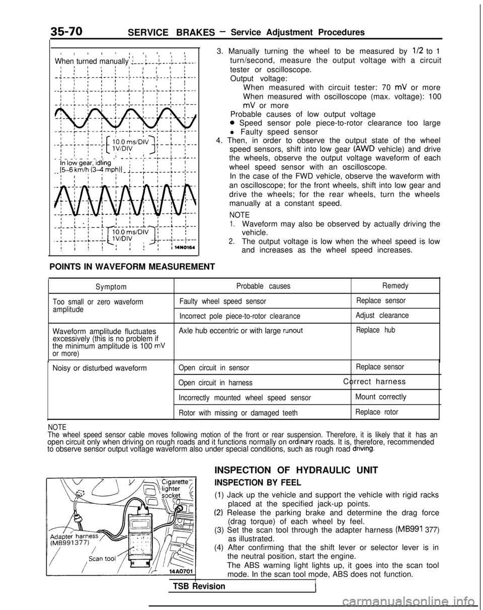
I, ! I ! I4 IO II IIWhen turned manually :---;---i-.-l---L--.I 8 ! IaI 1 11 1 II ’I 1’ I I I;-;--1---:--‘---+---t---i ’I IL---)-.-i---+--.II ’ I I 1 , 1 ,I
--:--~---;---:---~--~--
POINTS IN WAVEFORM MEASUREMENT
3. Manually turning the wheel to be measured by
l/2 to 1
turn/second, measure the output voltage with a circuit
tester or oscilloscope. Output voltage: When measured with circuit tester: 70
mV or more
When measured with oscilloscope (max. voltage): 100
mV or more
Probable causes of low output voltage
0 Speed sensor pole piece-to-rotor clearance too large
l Faulty speed sensor
4. Then, in order to observe the output state of the wheel
speed sensors, shift into low gear
(AWD vehicle) and drive
the wheels, observe the output voltage waveform of each
wheel speed sensor with an oscilloscope.
In the case of the FWD vehicle, observe the waveform with
an oscilloscope; for the front wheels, shift into low gear and
drive the wheels; for the rear wheels, turn the wheels manually at a constant speed.
NOTE
1.Waveform may also be observed by actually driving the
vehicle.
2.The output voltage is low when the wheel speed is low
and increases as the wheel speed increases.
Symptom
Too small or zero waveform amplitude Probable causes
Faulty wheel speed sensor Remedy
Replace sensor
Incorrect pole piece-to-rotor clearanceAdjust clearance
Waveform amplitude fluctuates Axle hub eccentric or with large runoutReplace hub
excessively (this is no problem if
the minimum amplitude is 100 mVor more)
Noisy or disturbed waveformOpen circuit in sensor Replace
sensor
Open circuit in harness
Correct harness
Incorrectly mounted wheel speed sensorMount correctly
Rotor with missing or damaged teeth Replace rotor
NOTEThe wheel speed sensor cable moves following motion of the front or rear\
suspension. Therefore, it is likely that it
has anopen circuit only when driving on rough roads and it functions normally \
on ordinan/ roads. It is, therefore, recommended
to observe sensor output voltage waveform also under special conditions,\
such as rough road dnvlng.
TSB Revision
INSPECTION OF HYDRAULIC UNIT
INSPECTION BY FEEL
(1) Jack up the vehicle and support the vehicle with rigid racks
placed at the specified jack-up points.
(2) Release the parking brake and determine the drag force(drag torque) of each wheel by feel.
(3) Set the scan tool through the adapter harness
(MB991 377)
as illustrated.
(4) After confirming that the shift lever or selector lever is in the neutral position, start the engine.
The ABS warning light lights up, it goes into the scan tool mode. In the scan tool mode, ABS does not function.
I
Page 1247 of 1273
35-126 SERVICE BRAKES - Wheel Speed Sensor
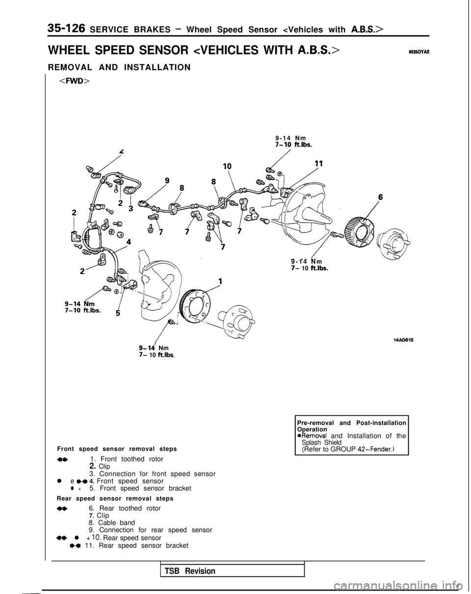
WHEEL SPEED SENSOR
REMOVAL AND INSTALLATION
9-14 Nm
7-10 ft.lbs.
9- ldNm7- 10 ft.lbs.
~~Q!-yJl~~@
9-14 N
m
7- 10
ft.lbs.
14A0615
Pre-removal and Post-installation
Operation
@Removal and Installation of theSplash Shield(Refer to GROUP
42-Fender.)
Front speed sensor removal steps
4w1. Front toothed rotor2. Clip3. Connection for front speed sensor
l e e+ 4. Front speed sensorl +5. Front speed sensor bracket
Rear speed sensor removal steps
*I)6. Rear toothed rotor 7. Clip
8. Cable band
9. Connection for rear speed sensor
+e l + 10. Rear speed sensorw+ 11. Rear speed sensor bracket
TSB Revision
/-..
Page 1248 of 1273
Pre-removal and Post-installation
SERVICE BRAKES - Wheel Speed Sensor
2
7-10 ftlbs.
7-10 ft.lbs.
9-14 Nm
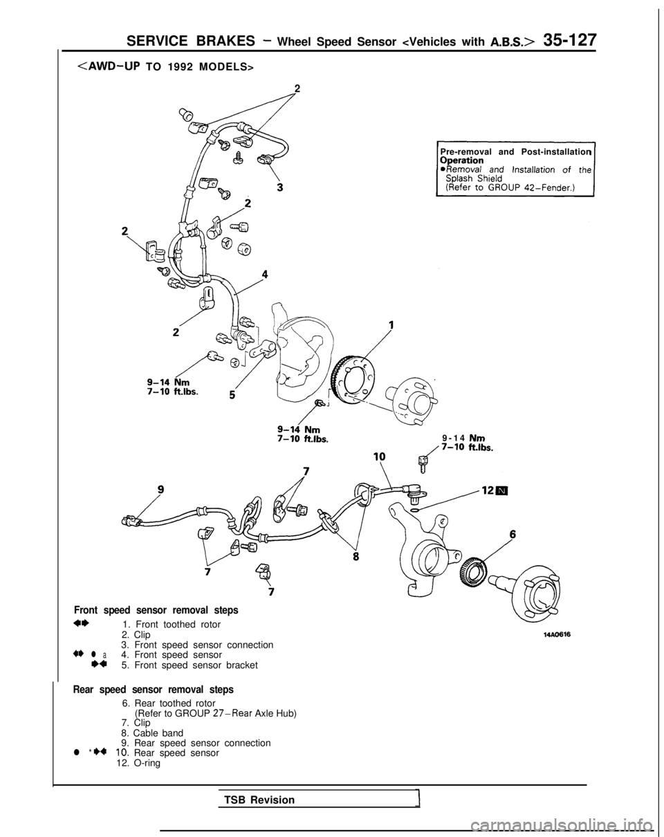
Front speed sensor removal steps
*I)1. Front toothed rotor
2. Clip
+* l a3. Front speed sensor connection
**4. Front speed sensor 5. Front speed sensor bracket
14AO616
Rear speed sensor removal steps
6. Rear toothed rotor (Refer to GROUP 27-Rear Axle Hub)
7. Clip
8. Cable band
l * I)49. Rear speed sensor connection10. Rear speed sensor
12. O-ring
TSB Revision
Page 1249 of 1273
35-128 SERVICE BRAKES - Wheel Speed Sensor
II 14AO215
Front speed sensor Rear speed sensorINSPECTION
Pole
hiecePole &ce
-
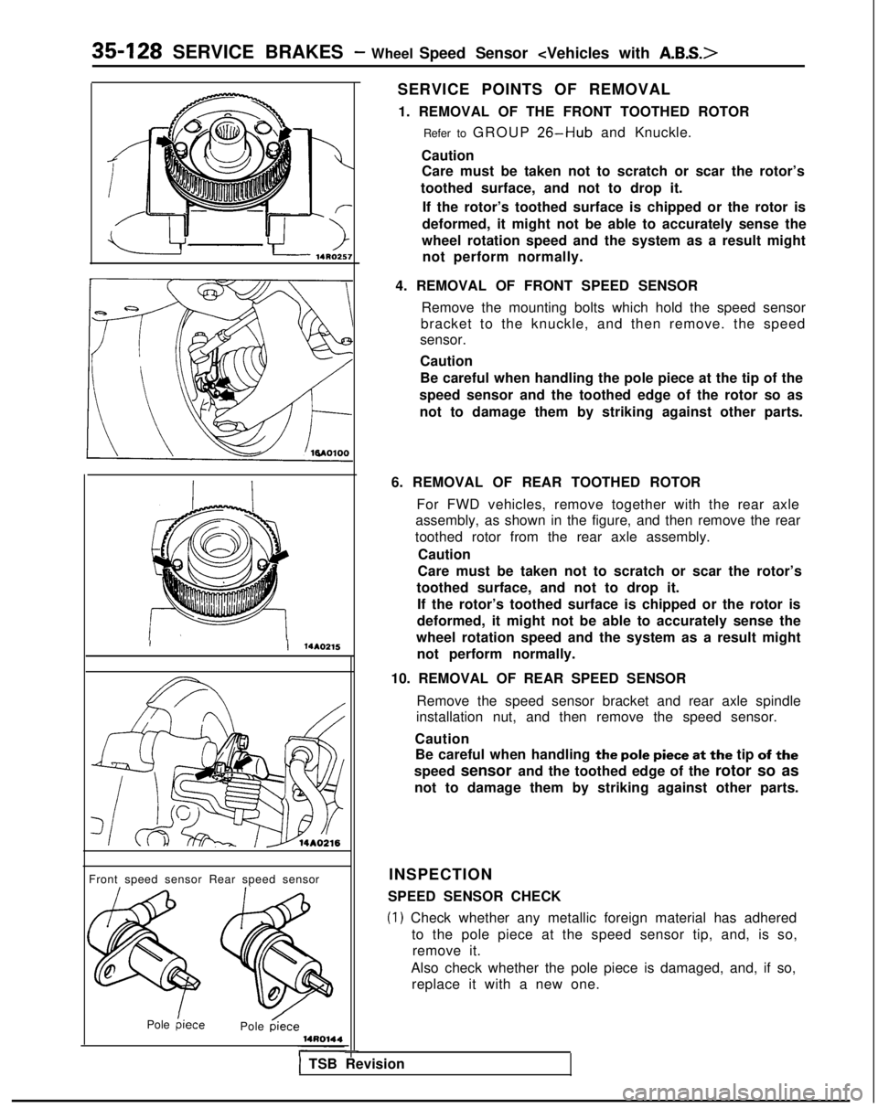
SERVICE POINTS OF REMOVAL 1. REMOVAL OF THE FRONT TOOTHED ROTOR Refer to GROUP
26-Hub and Knuckle.
Caution Care must be taken not to scratch or scar the rotor’s
toothed surface, and not to drop it.
If the rotor’s toothed surface is chipped or the rotor is
deformed, it might not be able to accurately sense the
wheel rotation speed and the system as a result might not perform normally.
4. REMOVAL OF FRONT SPEED SENSOR Remove the mounting bolts which hold the speed sensor
bracket to the knuckle, and then remove. the speed
sensor.
Caution
Be careful when handling the pole piece at the tip of the
speed sensor and the toothed edge of the rotor so as not to damage them by striking against other parts.
6. REMOVAL OF REAR TOOTHED ROTOR For FWD vehicles, remove together with the rear axle
assembly, as shown in the figure, and then remove the rear
toothed rotor from the rear axle assembly.
Caution
Care must be taken not to scratch or scar the rotor’s
toothed surface, and not to drop it. If the rotor’s toothed surface is chipped or the rotor is
deformed, it might not be able to accurately sense the
wheel rotation speed and the system as a result might not perform normally.
10. REMOVAL OF REAR SPEED SENSOR Remove the speed sensor bracket and rear axle spindle
installation nut, and then remove the speed sensor.
Caution Be careful when handling
the pole piece at the tip of the
speed sensor and the toothed edge of the
rotor so as
not to damage them by striking against other parts.
SPEED SENSOR CHECK
(1) Check whether any metallic foreign material has adhered to the pole piece at the speed sensor tip, and, is so,remove it.
Also check whether the pole piece is damaged, and, if so, replace it with a new one.
1 TSB Revision