1989 MITSUBISHI GALANT fuse
[x] Cancel search: fusePage 152 of 1273
13-10
FUEL SYSTEM
at sensor side
1\~“‘,““W,O,’ ‘\*N 4-cnDQ5a,, \llllf,,
c 3 c-11 ‘.<-!
( .[&
;%* \ g ~ &.$$~&%,;
0%: E
.Oj-,,
giI lOWI -,n
/ ~ ( ~~‘-~~~
-.mo .u. m,.0 - rj*> ;;
indicator lamp68AOO93
l
If the voltage (power-supply voltage) supplied to a sensor
is not normal, repair the harness. If the voltage to the sensor is still not normal after the har-
ness has been repaired, repalce the engine control module
and check again.
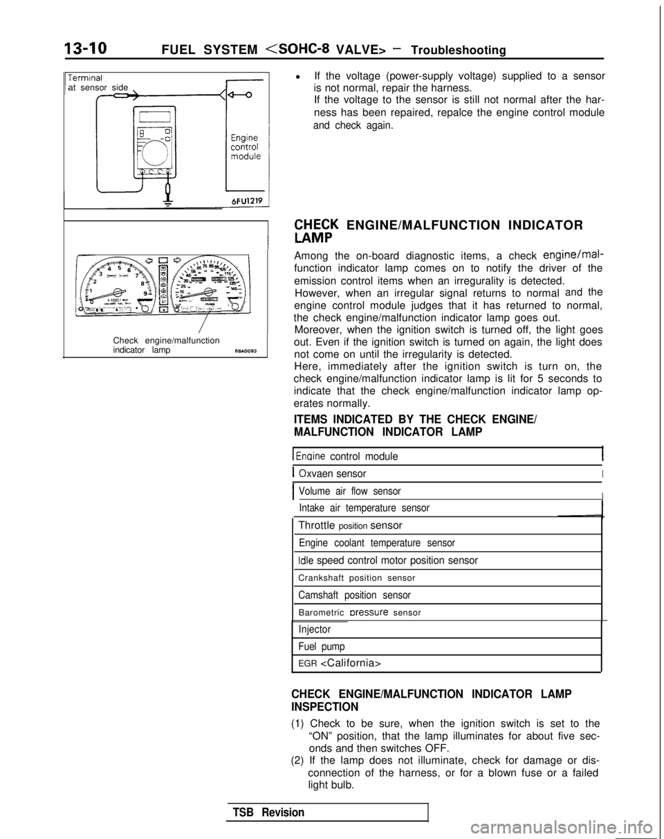
W&K ENGINE/MALFUNCTION INDICATOR
Among the on-board diagnostic items, a check
engine/mal-
function indicator lamp comes on to notify the driver of the
emission control items when an irregurality is detected. However, when an irregular signal returns to normal
andthe
engine control module judges that it has returned to normal,
the check engine/malfunction indicator lamp goes out. Moreover, when the ignition switch is turned off, the light goes
out. Even if the ignition switch is turned on again, the light does not come on until the irregularity is detected.
Here, immediately after the ignition switch is turn on, the
check engine/malfunction indicator lamp is lit for 5 seconds to indicate that the check engine/malfunction indicator lamp op-
erates normally.
ITEMS INDICATED BY THE CHECK ENGINE/
MALFUNCTION INDICATOR LAMP
1 Enaine control module
IOxvaen sensorI
IVolume air flow sensorIIntake air temperature sensor
Throttle position sensor
Engine coolant temperature sensor
Idle speed control motor position sensor
Crankshaft position sensor
Camshaft position sensor
Barometric rxessure sensor
Injector
Fuel pump
EGR
CHECK ENGINE/MALFUNCTION INDICATOR LAMP
INSPECTION
(1) Check to be sure, when the ignition switch is set to the “ON” position, that the lamp illuminates for about five sec-onds and then switches OFF.
(2) If the lamp does not illuminate, check for damage or dis-
connection of the harness, or for a blown fuse or a failedlight bulb.
TSB Revision
Page 262 of 1273
13-120FUEL SYSTEM
CHH;K
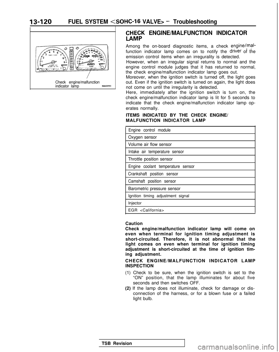
ENGINE/MALFUNCTION INDICATOR
Among the on-board diagnostic items, a check engine/mal-
function indicator lamp comes on to notify the driver
of the
emission control items when an irregurality is detected. However, when an irregular signal returns to normal and the
engine control module judges that it has returned to normal,
the check engine/malfunction indicator lamp goes out. Moreover, when the ignition switch is turned off, the light goes
Check engine/malfunctionout. Even if the ignition switch is turned on again, the light doesindicator lamp68A.0093not come on until the irregularity is detected.
Here, immediately after the ignition switch is turn on, the
check engine/malfunction indicator lamp is lit for 5 seconds to indicate that the check engine/malfunction indicator lamp op-
erates normally.
ITEMS INDICATED BY THE CHECK ENGINE/
MALFUNCTION INDICATOR LAMP
Engine control module
Oxygen sensor
Volume air flow sensor
Intake air temperature sensor
Throttle position sensor
Engine coolant temperature sensor
Crankshaft position sensor Camshaft position sensor
Barometric pressure sensor
Ignition timing adjustment signal
Injector
EGR
Caution
Check engine/malfunction indicator lamp will come on
even when terminal for ignition timing adjustment is short-circuited. Therefore, it is not abnormal that the
light comes on even when terminal for ignition timing
adjustment is short-circuited at the time of ignition tim-
ing adjustment.
CHECK ENGINE/MALFUNCTION INDICATOR LAM
P
INSPECTION
(1) Check to be sure, when the ignition switch is set to the “ON” position, that the lamp illuminates for about five
seconds and then switches OFF.
(2) If the lamp does not illuminate, check for damage or dis- connection of the harness, or for a blown fuse or a failedlight bulb.
TSB Revision
Page 347 of 1273
FUEL SYSTEM
Check engine/malfunctionindicator lamp6w.0093
TROUBLESHOOTINGM13EBADa
EXPLANATION O
F
PROCEDURES
Refer to P.13-8.
TROUBLESHOOTING
EXPLANATION AND PRECAUTION RELATED
TO HARNESS CHECKING
Refer to
P.13-9.
ft&;K ENGINE/MALFUNCTION INDICATO
R
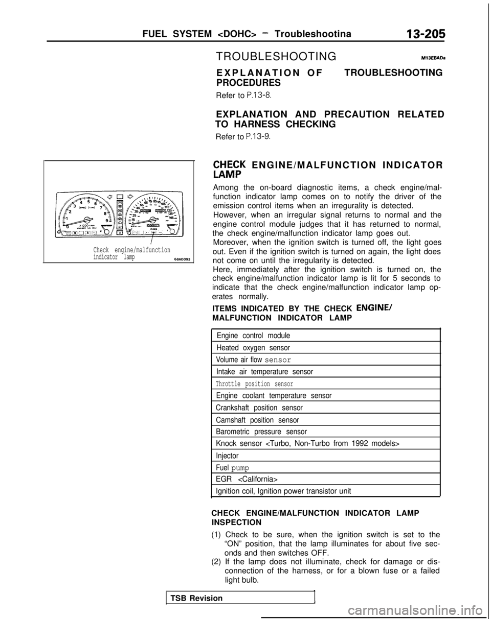
Among the on-board diagnostic items, a check engine/mal-
function indicator lamp comes on to notify the driver of the
emission control items when an irregurality is detected. However, when an irregular signal returns to normal and the
engine control module judges that it has returned to normal,
the check engine/malfunction indicator lamp goes out. Moreover, when the ignition switch is turned off, the light goes
out. Even if the ignition switch is turned on again, the light does
not come on until the irregularity is detected. Here, immediately after the ignition switch is turned on, the
check engine/malfunction indicator lamp is lit for 5 seconds to
indicate that the check engine/malfunction indicator lamp op-
erates normally.
ITEMS INDICATED BY THE CHECK ENGINE/
MALFUNCTION INDICATOR LAMP
Engine control module
Heated oxygen sensor
Volume air flow sensor
Intake air temperature sensor
Throttle position sensor
Engine coolant temperature sensor
Crankshaft position sensor
Camshaft position sensor
Barometric pressure sensor
Knock sensor
Injector
Fuel pump
EGR
Ignition coil, Ignition power transistor unit
CHECK ENGINE/MALFUNCTION INDICATOR LAMP INSPECTION
(1) Check to be sure, when the ignition switch is set to the “ON” position, that the lamp illuminates for about five sec-
onds and then switches OFF.
(2) If the lamp does not illuminate, check for damage or dis-
connection of the harness, or for a blown fuse or a failed
light bulb.
TSB Revision
Page 481 of 1273
AUTO-CRUISE CONTROL SYSTEM - Troubleshooting13-339
CHECK CHART
1. CHECKING THE CONTROL UNIT POWER SUPPLY CIRCUIT
Ignition
switch
(8)
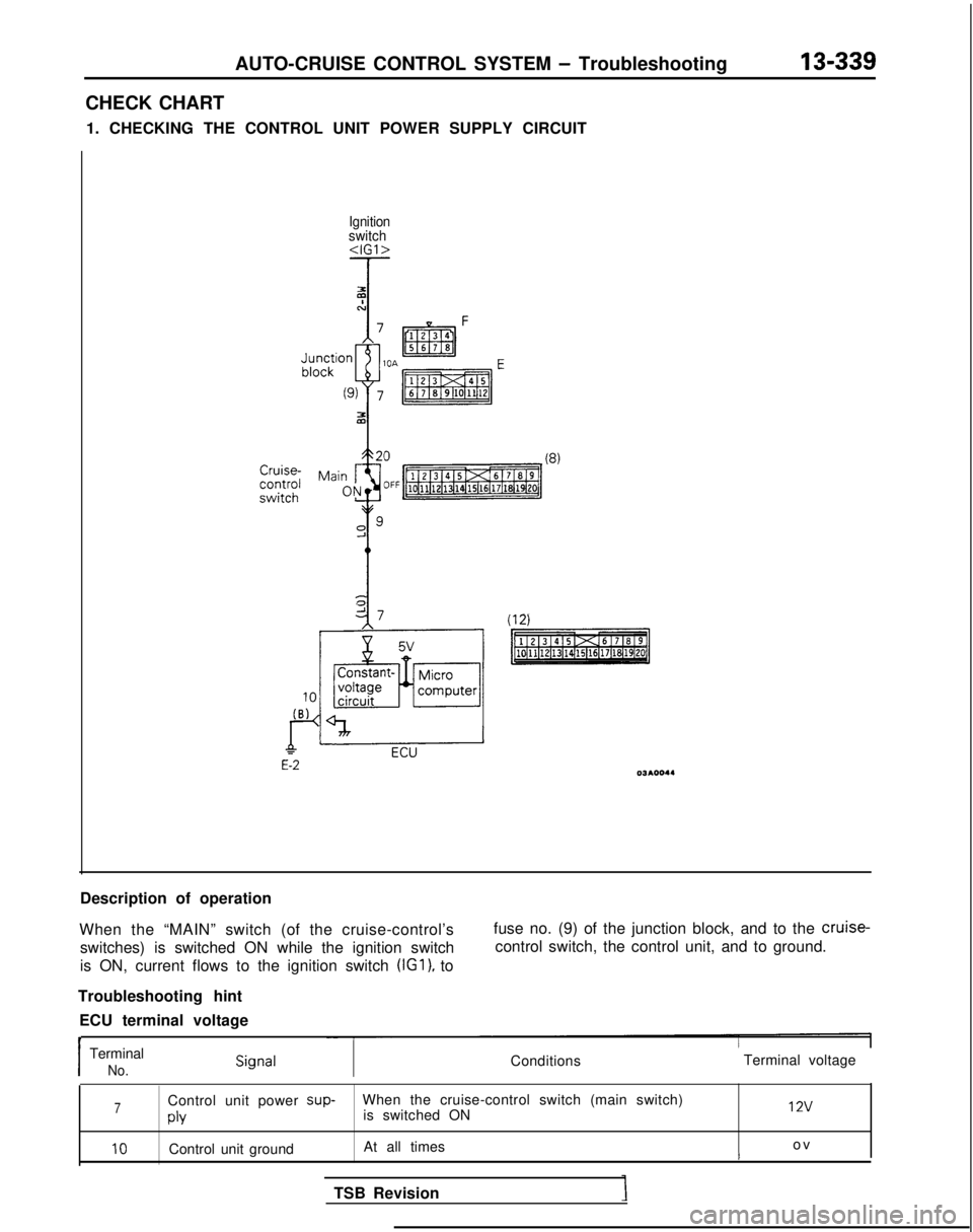
Description of operation
When the “MAIN” switch (of the cruise-control’s switches) is switched ON while the ignition switch
is ON, current flows to the ignition switch (IGl),
to fuse no. (9) of the junction block, and to the cruise-
control switch, the control unit, and to ground.
Troubleshooting hint ECU terminal voltage
t
Terminal voltageI
Terminal
No.Conditions
7Control unit power sup-
When the cruise-control switch (main switch)
is switched ON 12v
PlY
10Control unit ground
At all times o
v
t
TSB Revision
Page 485 of 1273
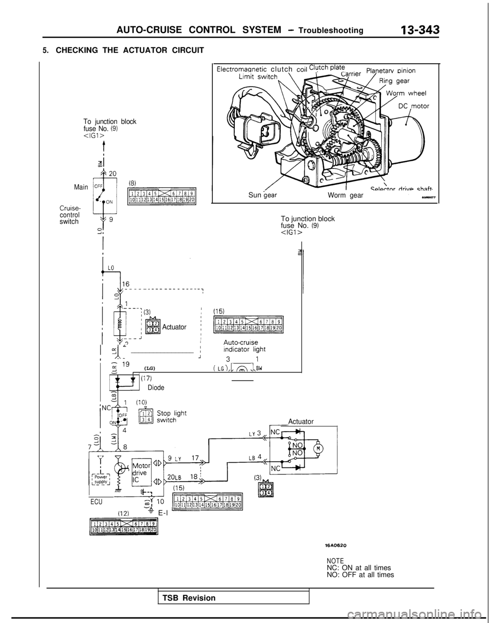
AUTO-CRUISE CONTROL SYSTEM - Troubleshooting
5.CHECKING THE ACTUATOR CIRCUIT
Electromannetic clutch coil Clutch @at’!Planetarv oinion
To junction block
fuse No. (9)
Ccdtnr riri\mchnftMainSun
control
switchTo junction block
fuse No. (9)
Actuator
/ (15)
p$%Emig
jyl; _________________ ;F:;;:ght
z " (LG)-1( LG),l A ,l\BWI(17)
Diode2d 111n\
Actuator
ECU
(12)-+ E-l -
1610620
NOTENC: ON at all times
NO: OFF at all times
TSB Revision
Page 487 of 1273
AUTO-CRUISE CONTROL SYSTEM - Troubleshooting13-345
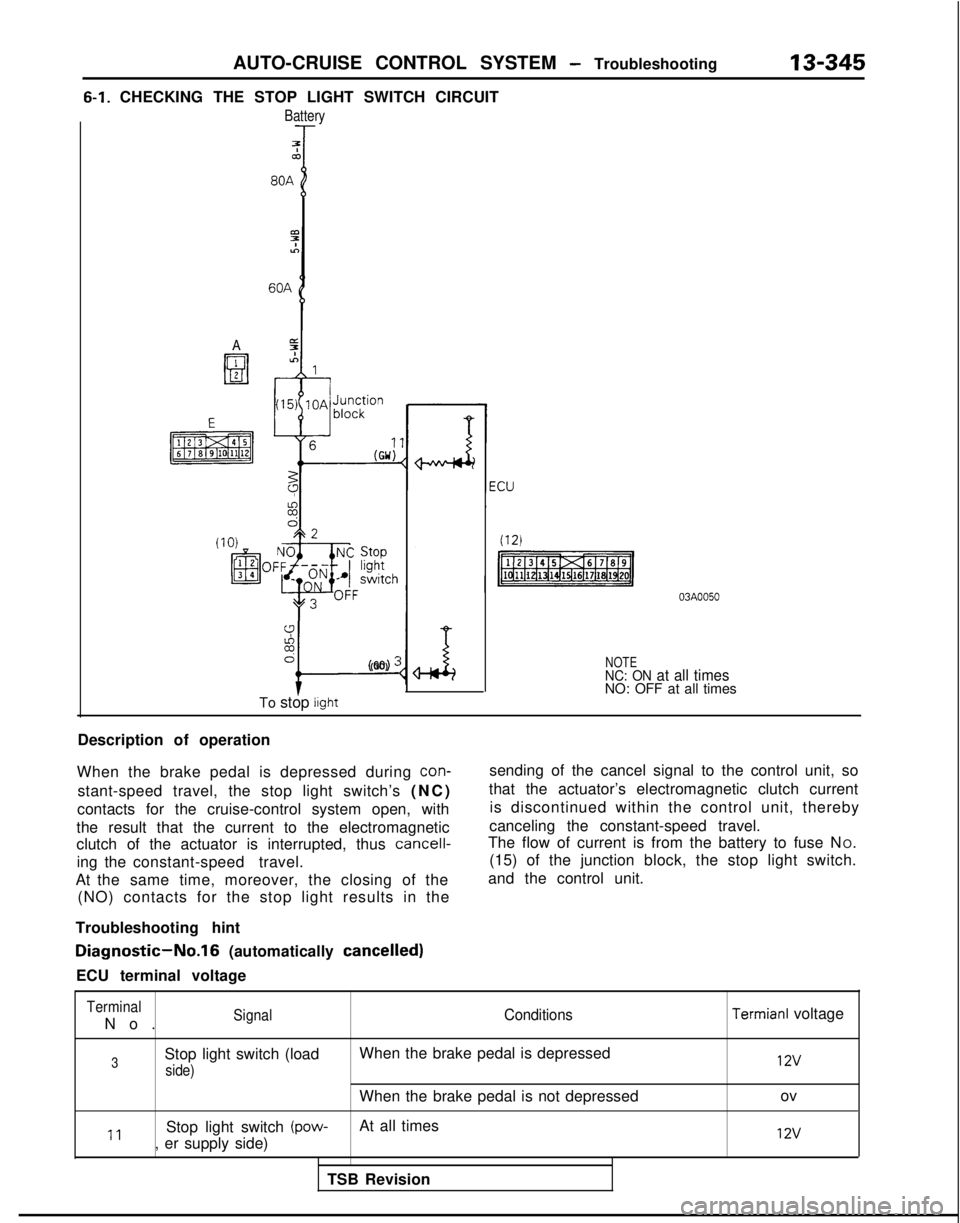
6-1. CHECKING THE STOP LIGHT SWITCH CIRCUIT
Battery
7Tco
A
9%6
I-
(GO) :
To stop light
NOTENC: ON at all timesNO: OFF at all times
Description of operation
When the brake pedal is depressed during
con-
stant-speed travel, the stop light switch’s (NC
)
contacts for the cruise-control system open, with
the result that the current to the electromagnetic
clutch of the actuator is interrupted, thus
cancell-
ing the constant-speed travel.
At the same time, moreover, the closing of the (NO) contacts for the stop light results in the
Troubleshooting hint sending of the cancel signal to the control unit, so
that the actuator’s electromagnetic clutch current is discontinued within the control unit, thereby
canceling the constant-speed travel.
The flow of current is from the battery to fuse N O.
(15) of the junction block, the stop light switch.
and the control unit.
Diagnostic-No.16 (automatically cancelled)
ECU terminal voltage
Terminal
No
.
SignalConditions
3Stop light switch (load
When the brake pedal is depressed
side)
When the brake pedal is not depressed
11Stop light switch (pow-At all times
, er supply side)
TSB Revision
Termianl voltage 12v
ov
12v
Page 489 of 1273
AUTO-CRUISE CONTROL SYSTEM - Troubleshooting13-347
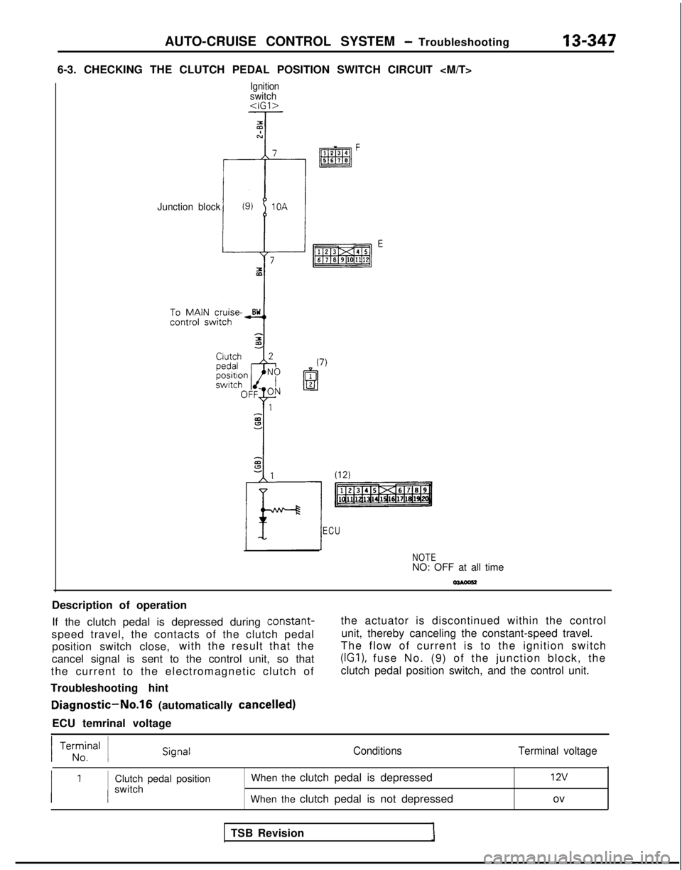
6-3. CHECKING THE CLUTCH PEDAL POSITION SWITCH CIRCUIT
Ignition
switch
Junction block
ECU
NOTENO: OFF at all time
Description of operation If the clutch pedal is depressed during constant-
speed travel, the contacts of the clutch pedal position switch close, with the result that the
cancel signal is sent to the control unit, so that
the current to the electromagnetic clutch of
Troubleshooting hint
Diagnostic-No.16 (automatically cancelled)
ECU temrinal voltage the actuator is discontinued within the control
unit, thereby canceling the constant-speed travel.
The flow of current is to the ignition switch (IGI),
fuse No. (9) of the junction block, the
clutch pedal position switch, and the control unit.
/ Te;z,nal 1Conditions Terminal voltage
Clutch pedal position
switch When the clutch pedal is depressed
When the clutch pedal is not depressed12v
ov
TSB Revision
Page 496 of 1273
13-354AUTO-CRUISE CONTROL SYSTEM - Troubleshooting
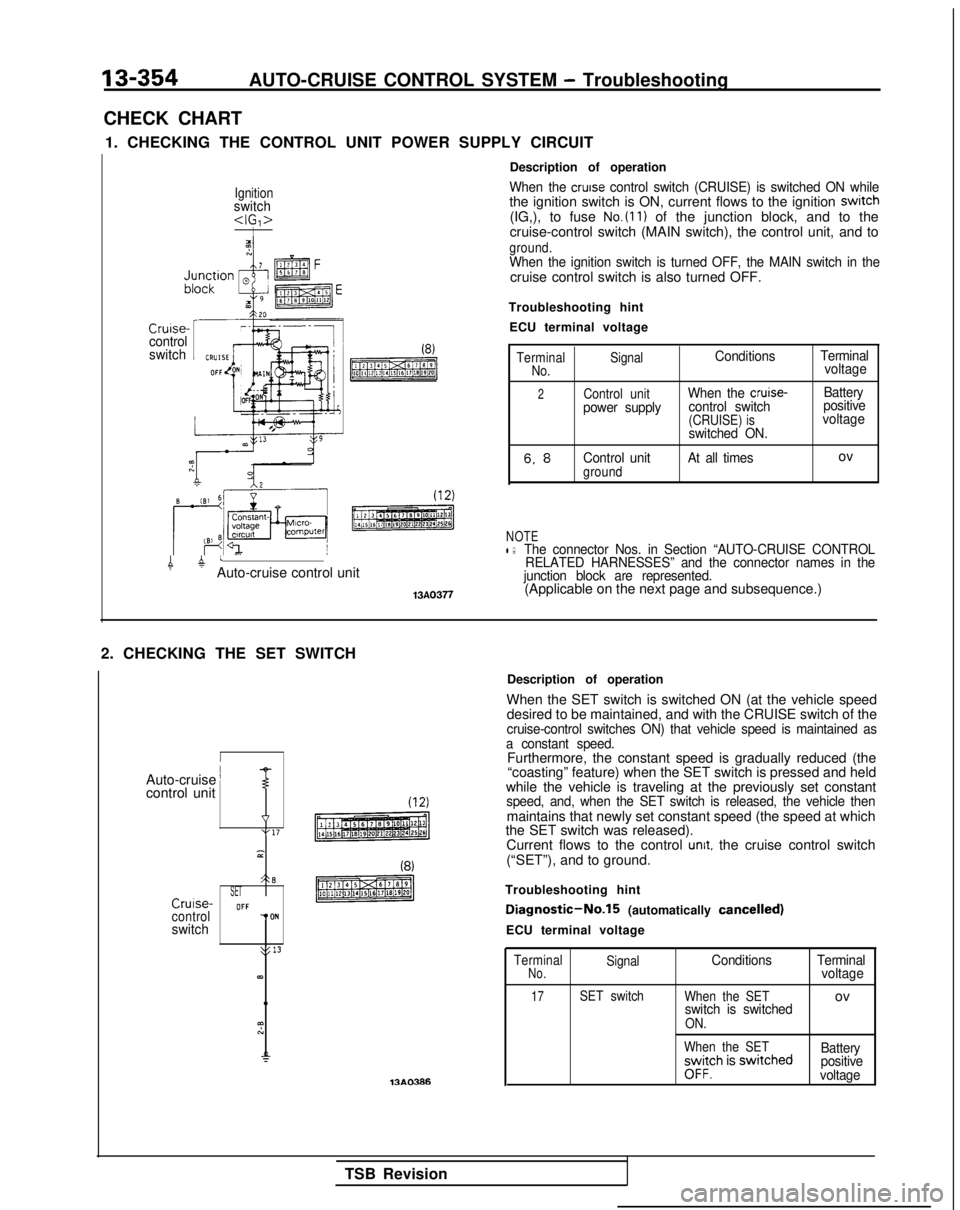
CHECK CHART 1. CHECKING THE CONTROL UNIT POWER SUPPLY CIRCUIT
Ignitionswitch
Cruise-control
switchI(8)
pmTzREq
4 atAuto-cruise control unit
13A0377
Description of operation
When the cruise control switch (CRUISE) is switched ON whilethe ignition switch is ON, current flows to the ignition swrtch(IG,), to fuse No.(ll) of the junction block, and to the
cruise-control switch (MAIN switch), the control unit, and to
ground.When the ignition switch is turned OFF, the MAIN switch in thecruise control switch is also turned OFF.
Troubleshooting hint ECU terminal voltage
Terminal SignalConditions TerminalNo.voltage
2Control unitWhen the cruise-Battery
power supply control switch positive
(CRUISE) isvoltage
switched ON.
6. 8Control unitgroundAt all timesov
NOTEl :The connector Nos. in Section “AUTO-CRUISE CONTROL RELATED HARNESSES” and the connector names in the
junction block are represented.
(Applicable on the next page and subsequence.)
2. CHECKING THE SET SWITCH
I
Auto-cruise ’control unitT
v“17 3
A-3SETCrulse-OFFcontrolTONswitch
>: 13
63)
13AO386Description of operation
When the SET switch is switched ON (at the vehicle speed desired to be maintained, and with the CRUISE switch of the
cruise-control switches ON) that vehicle speed is maintained as
a constant speed.
Furthermore, the constant speed is gradually reduced (the “coasting” feature) when the SET switch is pressed and held
while the vehicle is traveling at the previously set constant
speed, and, when the SET switch is released, the vehicle thenmaintains that newly set constant speed (the speed at which
the SET switch was released).
Current flows to the control
unit. the cruise control switch
(“SET”), and to ground.
Troubleshooting hint
Diagnostic-No.15 (automatically cancelled)
ECU terminal voltage
Terminal SignalConditions TerminalNo.voltage
17SET switch
When the SETovswitch is switchedON.
When the SET
;yv$h is swrtched Battery
positive
voltage
TSB Revision