1989 MITSUBISHI GALANT stop start
[x] Cancel search: stop startPage 954 of 1273

ACTIVE-ELECTRONIC CONTROL SUSPENSION - Troubleshootina 33B-15
Diagnostic
trouble
code NoMalfunction Vehicle condition Probable causeAction
52
Damaged or disconnected
The alarm light illuminates, l Damaged or disconnected Troubleshoo
wiring of the left front or and the attitude-control wiring of the left front or
ing hints
right front valve actuation function and the vehicle- right front valve coil.
classified by
circuit, or a malfunction of height control function arel Damaged or disconnected circuit
[25]an output transistor within
stopped. wiring of the left front orthe ECU.The damping force is held
right front valve circuit
to MEDIUM. harness.
l Disconnection of the connector of the left front
or right front valve circuit.
l ECU malfunction.
53
Damaged or disconnected The alarm light illuminates,
wiring of the left rear or right l Damaged or disconnected Troubleshoot
and the attitude-control wiring of the left rear or
rear valve actuation circuit, ing hints
function and, the vehicle- right rear valve coil.
classified by
or a malfunction of an output height control function are
transistor within the ECU. l Damaged or disconnected circuit
[26]
stopped.
wiring of the left rear or
The damping force is held right rear valve circuit
to MEDIUM.
harness.
l Disconnection of the connector of the left rear
or right rear valve circuit.
l ECU malfunction.
54
55
Even though three mrnutes
The alarm light illuminates,0 Overloaded condition. Refer to
or more have passed for the and the attitude-control l Improper adjustment ofMalfunction
vehicle-height adjustments function and the vehicle- the front or rear
of the front and the rear, and Symptoms
height control function are vehicle-height sensor.
Chart [A] onthe pressure within thestopped.l Air-pressure line isP.33B-17.high-pressure
tank is
The damping force is held
sufficient (the high-pressure clogged.
to MEDIUM. l Malfunction of the front
switch is OFF), the strut unit or the rear shock
vehicle-height adjustments absorber unit air spring.
are not completed. l ECU malfunction.
Even though three minutes The alarm light illuminates,
l Compressor malfunction.Refer to
or more have passed for the and the attitude-control Damaged orMalfunction
vehicle-height adjustments function and the vehicle- disconnected wiring ofSymptoms
of the front and the rear, and height control function are
the harness between theChart
LB1 on
with insufficient pressure stopped. compressor relay and the
P.33B-17.
withtn the high-pressure tankThe damping force is held
compressor.
(the high-pressure
switch isto MEDIUM.
Malfunction of the air
iON), the vehicle-height compression of the
adjustments are not compressor.
completed, or the l Air leakage from the
compressor has operated
continuously for four high-pressure tank
minutes or longer. (non-airtight connection
with the low-pressure
tank).
l High-pressure switch is fused.
The return pump is Control functions are not Air leakage within the frontReplace the
continuously activated stopped (alarm lamp does (left or right) or rear (left orfront or rear
(repeatedly starts and stops not illuminate).
right) valve.solenoid
56erght times), even though
valve.
neither the attitude-control
function nor the
vehicle-height control
function has been initiated.
TSB Revision
Page 1026 of 1273
ACTIVE-ELECTRONIC CONTROL SUSPENSIONService Adjustment- Procedures33B-87
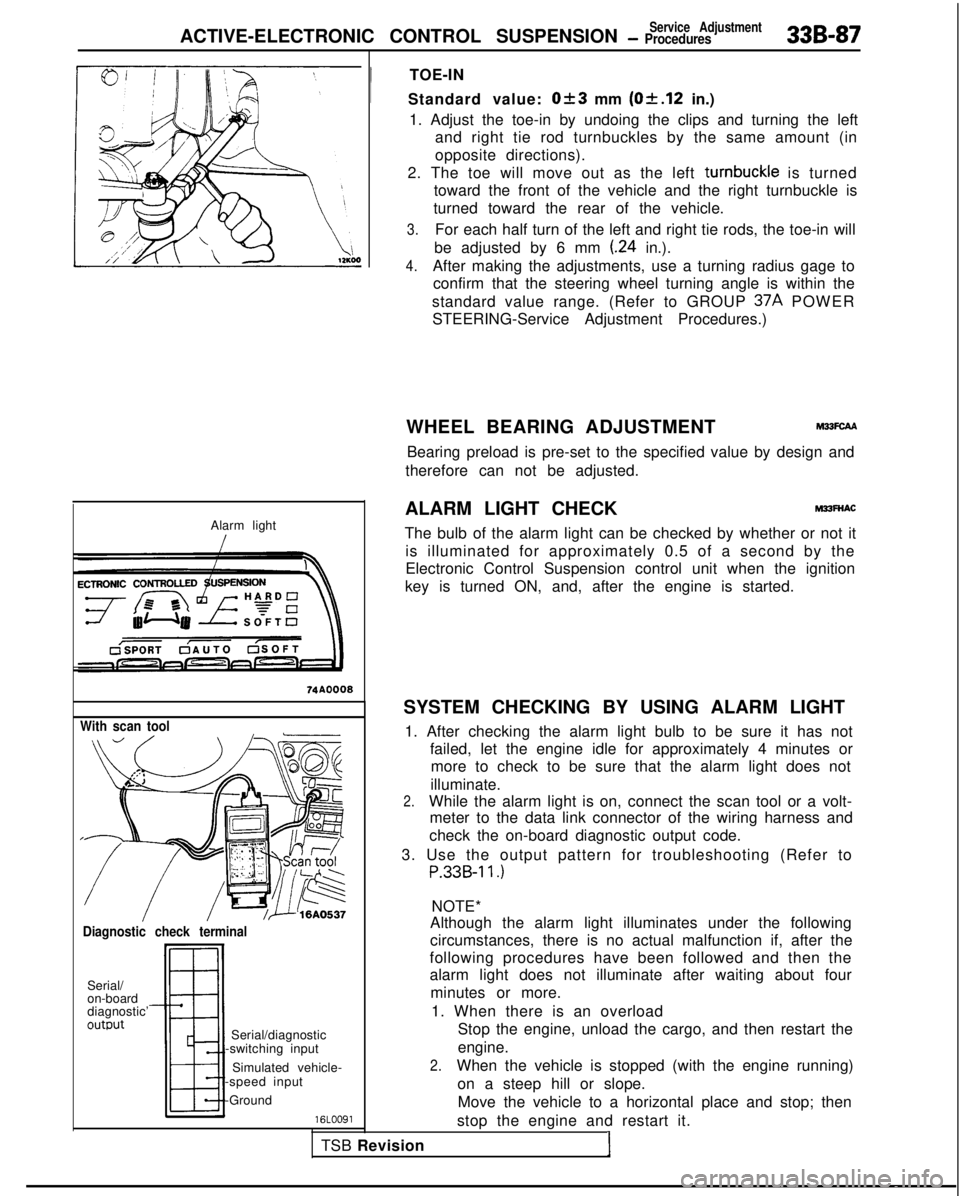
Alarm light
With scan tool
Diagnostic check terminal
Serial/
on-board
diagnostic’
outwt
TSB RevisionI
Serial/diagnostic
-switching input
Simulated vehicle-
-speed input
-Ground
16LOO91
!
TOE-IN
Standard value:
Ok3 mm (Of.12 in.)
1. Adjust the toe-in by undoing the clips and turning the left and right tie rod turnbuckles by the same amount (in
opposite directions).
2. The toe will move out as the left turnbuckle
is turned
toward the front of the vehicle and the right turnbuckle is
turned toward the rear of the vehicle.
3.For each half turn of the left and right tie rods, the toe-in will
be adjusted by 6 mm
(.24 in.).
4.After making the adjustments, use a turning radius gage to confirm that the steering wheel turning angle is within the
standard value range. (Refer to GROUP 37A
POWER
STEERING-Service Adjustment Procedures.)
WHEEL BEARING ADJUSTMENT
M33FcAA
Bearing preload is pre-set to the specified value by design and
therefore can not be adjusted.
ALARM LIGHT CHECK
MPFNAC
The bulb of the alarm light can be checked by whether or not it is illuminated for approximately 0.5 of a second by the
Electronic Control Suspension control unit when the ignition
key is turned ON, and, after the engine is started.
SYSTEM CHECKING BY USING ALARM LIGHT 1. After checking the alarm light bulb to be sure it has not failed, let the engine idle for approximately 4 minutes ormore to check to be sure that the alarm light does not
illuminate.
2.While the alarm light is on, connect the scan tool or a volt- meter to the data link connector of the wiring harness and
check the on-board diagnostic output code.
3. Use the output pattern for troubleshooting (Refer to
P.33B-11.)
NOTE*
Although the alarm light illuminates under the following
circumstances, there is no actual malfunction if, after the
following procedures have been followed and then the
alarm light does not illuminate after waiting about four
minutes or more.
1. When there is an overload Stop the engine, unload the cargo, and then restart the
engine.
2.When the vehicle is stopped (with the engine running)
on a steep hill or slope.Move the vehicle to a horizontal place and stop; then
stop the engine and restart it.
Page 1027 of 1273
338-88 ACTIVE-ELECTRONIC CONTROL SUSPENSION - ~~~%.,~Rment
With voltmeter
!//ii’12A0476
L
edge surface17AOOW(Right
Front) (Left
Rear)
12A0224 J3. When vehicle-height adjustments are made frequently
After stopping the engine, open the hood and allowthe compressor to cool; then restart the engine.
4. When the vehicle is driven on winding roads in the
mountains continuously for 18 minutes or longer.
To protect the return pump from damage, stop the
engine and then restart it.
*: Applicable to 1989 models only.
CHECKING BY ON-BOARD DIAGNOSTIC
1.Regardless of whether or not the alarm light is illuminated,
check the diagnostic output codes at the diagnostic termi-
nal.
2. If a malfunction code is output to the diagnostic terminal, perform the troubleshooting procedures according to the
output code.
NOTE
Diagnostic trouble codes are entered into the memory, even if
the ignition is at the OFF position, so that it is possible to check
for the existence of malfunctions that occurred previously.
NORMAL VEHICLE HEIGHT CHECK AND ADJUST-
MENT
1. Park the vehicle on a flat surface.
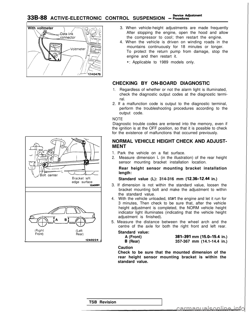
2.Measure dimension L (in the illustration) of the rear height
sensor mounting bracket installation location.
Rear height sensor mounting bracket installation
length:
Standard value (L): 314-316 mm (12.36-12.44 in.)
3. If dimension is not within the standard value, loosen the bracket mounting bolt and make the adjustment to within
the standard value.
4.With the vehicle unloaded, start
the engine and let it run for
3 minutes, Then check to be sure that, after the vehicle
height adjustment is completed, the NORM vehicle height
indicator light illuminates (indicating that the vehicle height
adjustment is finished).
5. Measure the distance between the wheel arch and the centre of the axle for both the right front and left rear.
Standard value: A (Front)
381391 mm (15.9-15.4 in.) 6
(Rear)357-367 mm (14.1-14.4 in.)
Caution
Check to be sure that the mounted dimension of the rear height sensor mounting bracket is within the
standard value.
TSB Revision
Page 1028 of 1273
ACTIVE-ELECTRONIC CONTROL SUSPENSION - ~~:i%,~:iustment 33B-89
Without
disconnecting
:he air tubing
Remaining
pressure
P =
120 kPa
(17 psi)
By disconnecting the
fir tubing
normal
condition
P ‘=.0
Front
tear (From 1990
model!
rmzIIconditlui
12AO281
Vehicle-height switch 6. If the vehicle height is not within the standard value,
loosen the turnbuckles of the front and rear height sensor
rods, and then make the adjustment by changing the
length of the rods. The vehicle height becomes higher
when the rods are lengthened.
Caution 1. Both the front and rear heights must be checked, because, even though only the front or the rear is
adjusted, the other height (rear or front) is also
changed.
2. The adjustments of the vehicle height must be made
while the engine is idling (vehicle stopped).
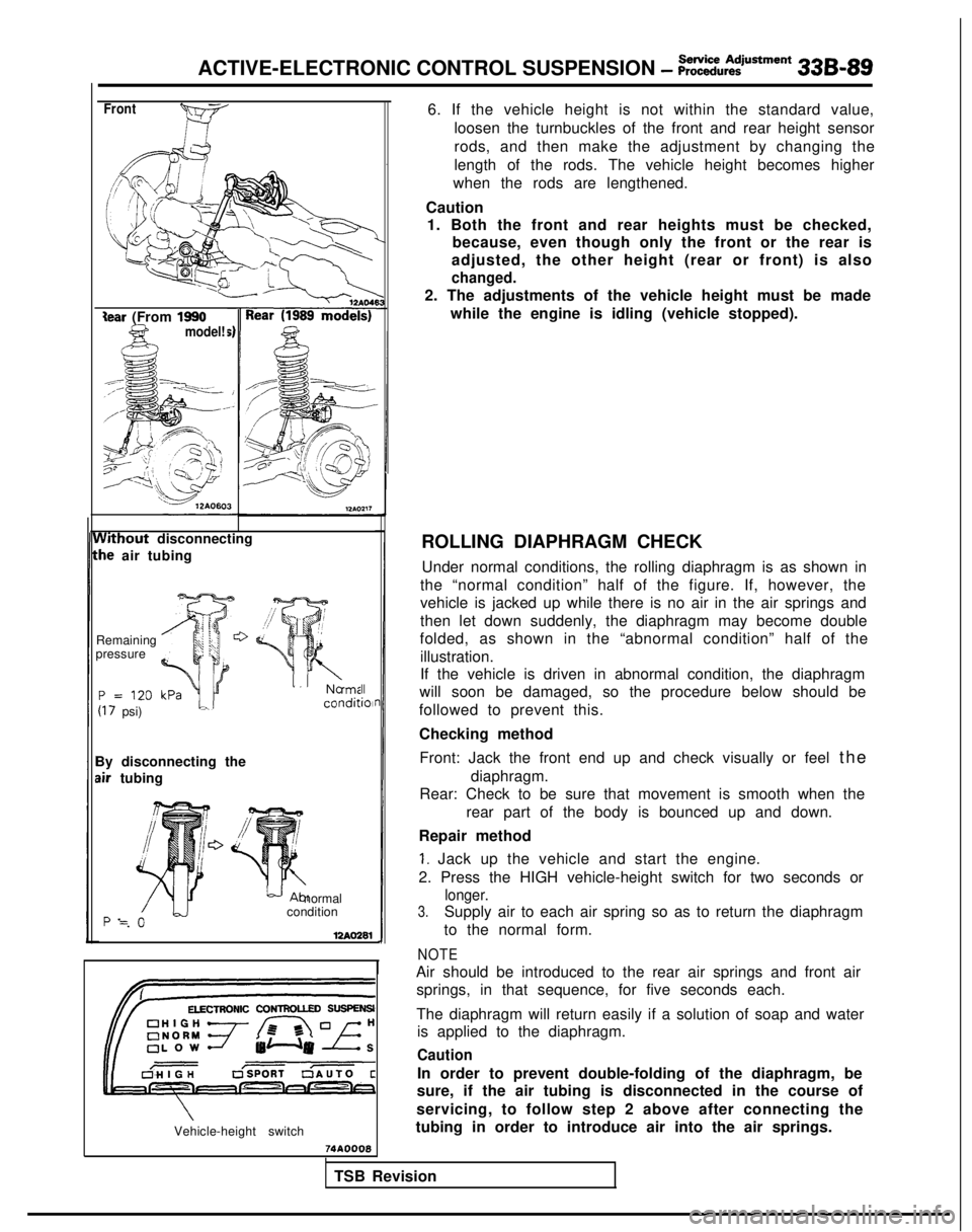
ROLLING DIAPHRAGM CHECK Under normal conditions, the rolling diaphragm is as shown in
the “normal condition” half of the figure. If, however, the
vehicle is jacked up while there is no air in the air springs and
then let down suddenly, the diaphragm may become double
folded, as shown in the “abnormal condition” half of the
illustration.
If the vehicle is driven in abnormal condition, the diaphragm
will soon be damaged, so the procedure below should be
followed to prevent this.
Checking method
Front: Jack the front end up and check visually or feel th
e
diaphragm.
Rear: Check to be sure that movement is smooth when the
rear part of the body is bounced up and down.
Repair method
1. Jack up the vehicle and start the engine.
2. Press the HIGH vehicle-height switch for two seconds or
longer.
3.Supply air to each air spring so as to return the diaphragm
to the normal form.
NOTE
Air should be introduced to the rear air springs and front air springs, in that sequence, for five seconds each.
The diaphragm will return easily if a solution of soap and water is applied to the diaphragm.
Caution
In order to prevent double-folding of the diaphragm, be
sure, if the air tubing is disconnected in the course of
servicing, to follow step 2 above after connecting the
tubing in order to introduce air into the air springs.
74AOOQ8
TSB Revision
Page 1031 of 1273
33B-92 ACTIVE-ELECTRONIC CONTROL SUSPENSION - ~~:%:?stment
CHECKING THE DAMPING FORCE
12A0279
Damping force characteristic
indicator lights
,\,IHARD 0 HARD 0 HARD;g!;
=-\\I, =\\ l,=0 -=-,F; f;F:
SOFT ,gi SOFT
:SOFT or(MEDIUM)(HARD)4UTOSOFT)12AQ271
./I,HARD 0HARD 0HARD ;g;
z-0 -\k 3,\I I,SOFT ;p;SOFT ;R-SOFT I@;
45” or more45” or more
stopSlight
Sharp
16AQ460
1. Move the wheels to the straight-ahead position.
2. Start the engine.
3. Set to the AUTO mode (normal vehicle height).
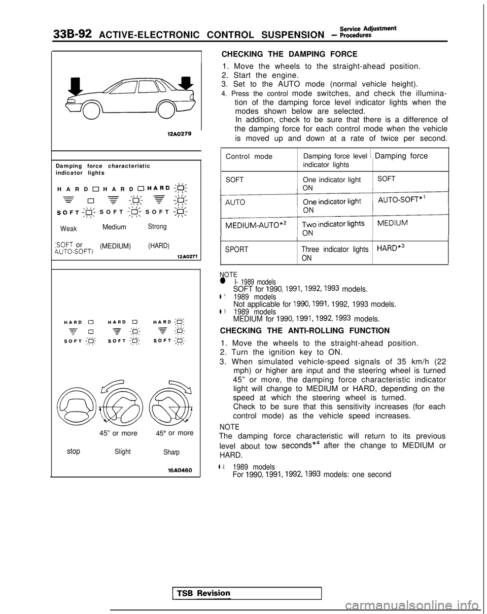
4. Press the control mode switches, and check the illumina-
tion of the damping force level indicator lights when themodes shown below are selected.In addition, check to be sure that there is a difference of
the damping force for each control mode when the vehicle
is moved up and down at a rate of twice per second.
Control mode Damping force level
1 Damping force
indicator lights
SOFTOne indicator light
ON SOFT
SPORT
I
Three indicator lightsHARDe3
ON
NOTEl I- 1989 modelsSOFT for 1990,1991,1992,1993 models.l *:1989 modelsNot applicable for 1990,1991, 1992, 1993 models.l 3:1989 modelsMEDIUM for 1990,1991,1992,1993 models.
CHECKING THE ANTI-ROLLING FUNCTION
1. Move the wheels to the straight-ahead position.
2. Turn the ignition key to ON.
3. When simulated vehicle-speed signals of 35 km/h (22 mph) or higher are input and the steering wheel is turned
45” or more, the damping force characteristic indicator light will change to MEDIUM or HARD, depending on the
speed at which the steering wheel is turned. Check to be sure that this sensitivity increases (for each
control mode) as the vehicle speed increases.
NOTE
The damping force characteristic will return to its previous
level about tow seconds*4
after the change to MEDIUM or
HARD.
l 4:1989 modelsFor 1990,1991,1992,1993
models: one second
Page 1032 of 1273
Service AdjustmentACTIVE-ELECTRONIC CONTROL SUSPENSION - Procedures33B-93
\\ I/HARD ;g;
7 #
SOFT;#c
\\ I/HARD ;F;
7 ;&
SOFT;@;
I12AO399
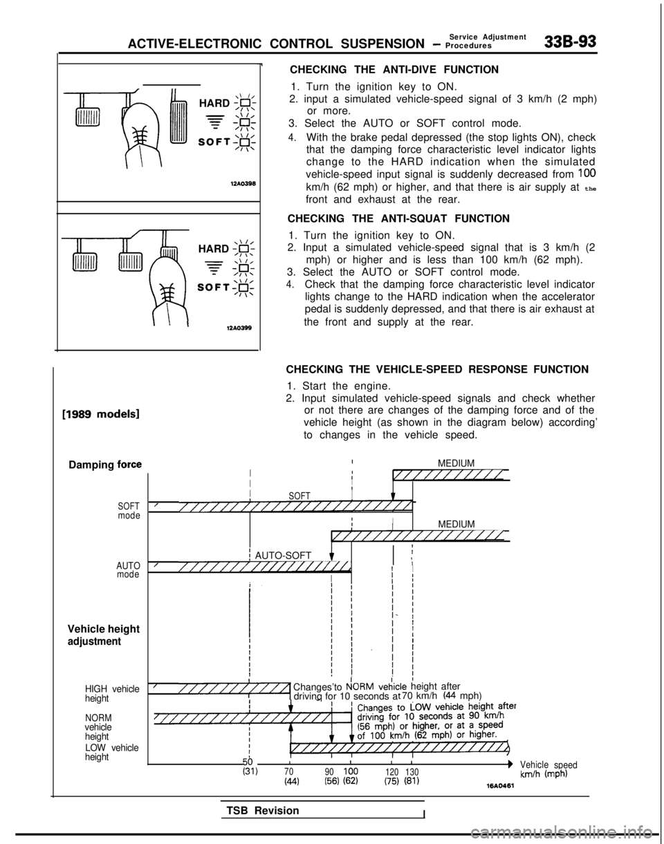
CHECKING THE ANTI-DIVE FUNCTION1. Turn the ignition key to ON.
2. input a simulated vehicle-speed signal of 3 km/h (2 mph) or more.
3. Select the AUTO or SOFT control mode.
4.With the brake pedal depressed (the stop lights ON), check
that the damping force characteristic level indicator lights
change to the HARD indication when the simulated
vehicle-speed input signal is suddenly decreased from
100
km/h (62 mph) or higher, and that there is air supply at the
front and exhaust at the rear.
CHECKING THE ANTI-SQUAT FUNCTION 1. Turn the ignition key to ON.
2. Input a simulated vehicle-speed signal that is 3 km/h (2
mph) or higher and is less than 100 km/h (62 mph).
3. Select the AUTO or SOFT control mode.
4.Check that the damping force characteristic level indicator lights change to the HARD indication when the accelerator
pedal is suddenly depressed, and that there is air exhaust at
the front and supply at the rear. [1989
models1
Damping force
SOFTmode
AUTO mode
Vehicle height
adjustment
HIGH vehicle
height
NORMvehicle
height
LOW vehicle
height
CHECKING THE VEHICLE-SPEED RESPONSE FUNCTION
1. Start the engine.
2. Input simulated vehicle-speed signals and check whether or not there are changes of the damping force and of the
vehicle height (as shown in the diagram below) according’
to changes in the vehicle speed.
IMEDIUMI1I//////////IIIII8SOFTI////////////////////////IIIIMEDIUMI////////////////
j AUTO-SOFT I ;I ,////////////////i//dI I
I
Ij I
I/Changes’to P!ORMveiic“““““1 drivinq for 10 seconds a:le height after t 70 km/h (44 mph)
III
I 1g,70
90100 120130bVehicle
speed
(44(56) (62)(75) (81)km/h (mph)1610461
TSB RevisionI
Page 1034 of 1273
ACTIVE-ELECTRONIC CONTROL SUSPENSION - ;;:i~%:?~~“~
33B-95
Adaptor E (MB991227)
Shut-off valve 12A.0350
iigh-pressure
witch
Air-pressure gauge (MB991075)
Adaptor C
(MB991 075.q
,daptor E (MB991226) /P-
3intH &‘xb
2.
3.
4.
5.
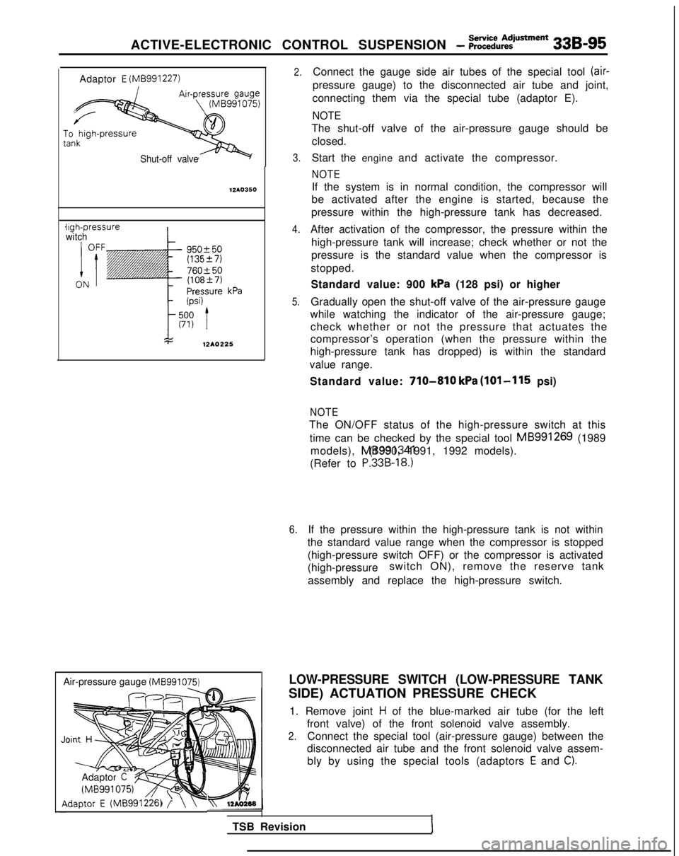
Connect the gauge side air tubes of the special tool (air-
pressure gauge) to the disconnected air tube and joint,
connecting them via the special tube (adaptor E).
NOTE
The shut-off valve of the air-pressure gauge should be closed.
Start the engine and activate the compressor.
NOTE
If the system is in normal condition, the compressor will
be activated after the engine is started, because the
pressure within the high-pressure tank has decreased.
After activation of the compressor, the pressure within the high-pressure tank will increase; check whether or not the
pressure is the standard value when the compressor is
stopped.
Standard value: 900
kPa (128 psi) or higher
Gradually open the shut-off valve of the air-pressure gauge
while watching the indicator of the air-pressure gauge; check whether or not the pressure that actuates the
compressor’s operation (when the pressure within the
high-pressure tank has dropped) is within the standard
value range.
Standard value:
710-810 kPa (101-115 psi)
NOTE
The ON/OFF status of the high-pressure switch at this time can be checked by the special tool MB991269
(1989
models), MB991341 (1990, 1991, 1992 models).
(Refer to
P.33B-18.)
6.If the pressure within the high-pressure tank is not within
the standard value range when the compressor is stopped
(high-pressure switch OFF) or the compressor is activated
(high-pressure switch ON), remove the reserve tank
assembly and replace the high-pressure switch.
LOW-PRESSURE SWITCH (LOW-PRESSURE TANK
SIDE) ACTUATION PRESSURE CHECK
1. Remove joint
H of the blue-marked air tube (for the left
front valve) of the front solenoid valve assembly.
2.Connect the special tool (air-pressure gauge) between the
disconnected air tube and the front solenoid valve assem-
bly by using the special tools (adaptors
E and C).
TSB RevisionI
Page 1035 of 1273
338-96
ACTIVE-ELECTRONIC CONTROL SUSPENSION - ;;~:;u~:iusment
Low-pressure
switch
PressurekPa (psi)
I
OFF
t
140 (20)
70 (10)
ON
12AO226
12A04P
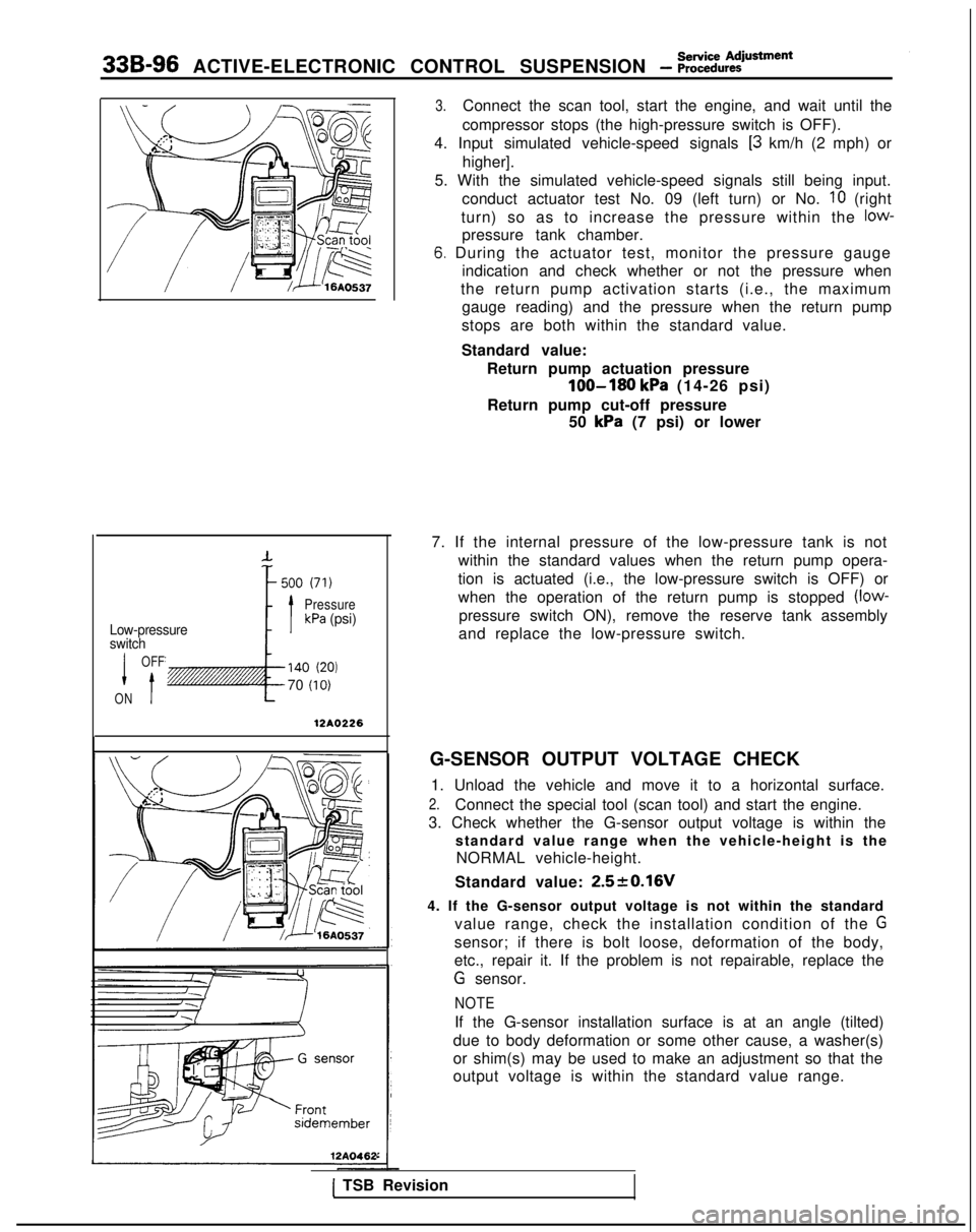
3.Connect the scan tool, start the engine, and wait until the
compressor stops (the high-pressure switch is OFF).
4. Input simulated vehicle-speed signals
[3 km/h (2 mph) or
higher].
5. With the simulated vehicle-speed signals still being input. conduct actuator test No. 09 (left turn) or No.
IO (right
turn) so as to increase the pressure within the
low-
pressure tank chamber.
6. During the actuator test, monitor the pressure gauge indication and check whether or not the pressure when
the return pump activation starts (i.e., the maximum gauge reading) and the pressure when the return pump
stops are both within the standard value.
Standard value: Return pump actuation pressure
loo-180 kPa (14-26 psi)
Return pump cut-off pressure 50
kPa (7 psi) or lower
7. If the internal pressure of the low-pressure tank is not within the standard values when the return pump opera-
tion is actuated (i.e., the low-pressure switch is OFF) or
when the operation of the return pump is stopped
(low-
pressure switch ON), remove the reserve tank assembly
and replace the low-pressure switch.
G-SENSOR OUTPUT VOLTAGE CHECK 1. Unload the vehicle and move it to a horizontal surface.
2.Connect the special tool (scan tool) and start the engine.
3. Check whether the G-sensor output voltage is within the standard value range when the vehicle-height is theNORMAL vehicle-height.
Standard value:
2.520.16V
4. If the G-sensor output voltage is not within the standard value range, check the installation condition of the
G
sensor; if there is bolt loose, deformation of the body,
etc., repair it. If the problem is not repairable, replace the
G sensor.
NOTE
If the G-sensor installation surface is at an angle (tilted)
due to body deformation or some other cause, a washer(s)
or shim(s) may be used to make an adjustment so that the
output voltage is within the standard value range.
1 TSB Revision