1989 MITSUBISHI GALANT clutch
[x] Cancel search: clutchPage 144 of 1273
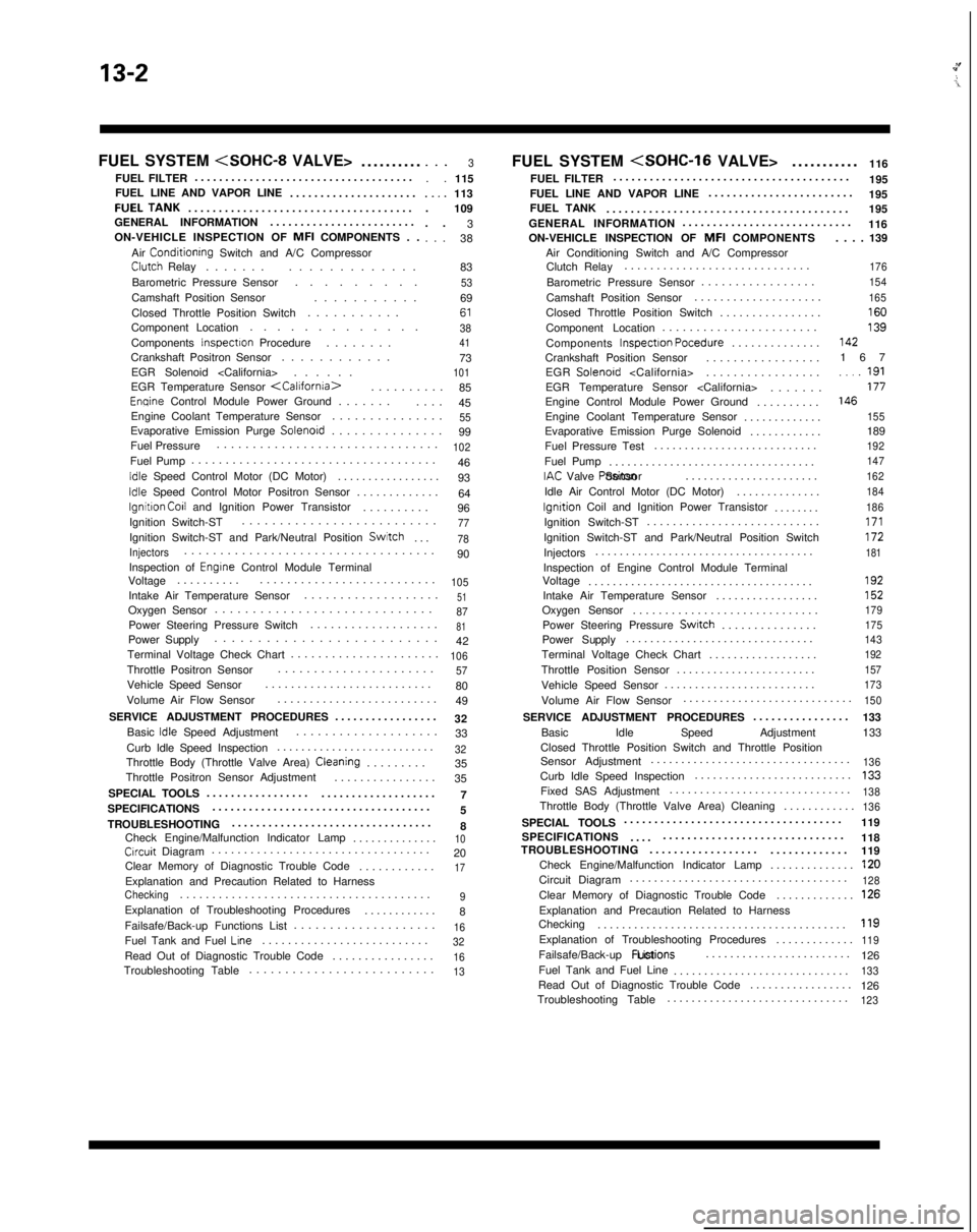
13-2
FUEL SYSTEM
..........
FUEL FILTER ....................................
FUEL LINE AND VAPOR LINE .....................FUELTANK....................................
.
GENERAL INFORMATION ........................
ON-VEHICLE INSPECTION OF MFI
COMPONENTS . .
Air
Conditionrng Switch and A/C CompressorClutch Relay ......
.
.............
Barometric Pressure Sensor .........
Camshaft Position Sensor ...........
Closed Throttle Position Switch ...........
Component Location .............
Components
Inspectron Procedure .......
.
Crankshaft Positron Sensor ............
EGR Solenoid
. . .3. .
115..,.113
. 109
. . 3
. . . 38
83
536961384173101EGR Temperature Sensor
.
85
Enqine Control Module Power Ground ......
.
....
45
Engine Coolant Temperature Sensor ...............
55Evaporative Emission Purge Solenord..............
.
99
Fuel Pressure ...............................
102Fuel Pump
...................................
.
46
Idle Speed Control Motor (DC Motor) ................
.
93
Idle Speed Control Motor Positron Sensor ............
.
64
lgnitron Co11 and Ignition Power Transistor .........
.
96
Ignition Switch-ST ..........................
77Ignition Switch-ST and Park/Neutral Position Switch
...78
Injectors..................................
.
90
Inspection of
Engrne Control Module Terminal
Voltage .........
.
..........................
105Intake Air Temperature Sensor ..................
.
51Oxygen Sensor
............................
.
87Power Steering Pressure Switch
..................
.
81Power Supply
.........................
.
42
Terminal Voltage Check Chart ......................
106Throttle Positron Sensor.....................
.
57Vehicle Speed Sensor
.........................
.
80
Volume Air Flow Sensor .........................
49
SERVICE ADJUSTMENT PROCEDURES .................
32
Basic
Idle Speed Adjustment ...................
.
33
Curb Idle Speed Inspection ..........................
32Throttle Body (Throttle Valve Area) Cleaning........
.
35
Throttle Positron Sensor Adjustment ................
35
SPECIAL TOOLS 7
.................
...................
SPECIFICATIONS ....................................
5
TROUBLESHOOTING .................................
8
Check Engine/Malfunction Indicator Lamp ..............
10Crrcuit Diagram.................................
.
20
Clear Memory of Diagnostic Trouble Code ............
17Explanation and Precaution Related to HarnessChecking......................................
.
9Explanation of Troubleshooting Procedures
...........
.
8
Failsafe/Back-up Functions List ....................
16Fuel Tank and Fuel Lrne.........................
.
32Read Out of Diagnostic Trouble Code
...............
.
16Troubleshooting Table
.........................
.
13
FUEL SYSTEM
116
FUEL FILTER .......................................
195
FUEL LINE AND VAPOR LINE ........................
195
FUEL TANK ........................................ 195
GENERAL INFORMATION ............................
116
ON-VEHICLE INSPECTION OF MFI
COMPONENTS
Air Conditioning Switch and A/C Compressor Clutch Relay .............................
Barometric Pressure Sensor .................
Camshaft Position Sensor ....................
Closed Throttle Position Switch ................
Component Location .......................
Components Inspectron Pocedure
..............
Crankshaft Position Sensor .................
EGR Solenoid
EGR Temperature Sensor
Engine Control Module Power Ground ..........
Engine Coolant Temperature Sensor .............
Evaporative Emission Purge Solenoid ............
Fuel Pressure Test ...........................
Fuel Pump ..................................
IAC Valve Positon Sensor
......................
Idle Air Control Motor (DC Motor) ..............
lgnrtion Coil and Ignition Power Transistor
.......
.
Ignition Switch-ST ...........................
Ignition Switch-ST and Park/Neutral Position Switch
Injectors ....................................
Inspection of Engine Control Module Terminal
Voltage .....................................
Intake Air Temperature Sensor .................
Oxygen Sensor .............................
Power Steering Pressure
Swatch..............
.
Power Supply ...............................
Terminal Voltage Check Chart ..................
Throttle Position Sensor .......................
Vehicle Speed Sensor ......................... . . . . 139
176
154
165
16013914216
7
..,_ 191177146
155
189192
147
162
184
186
171172181
192152
179
175
143
192
157
173
Volume Air Flow Sensor ...........................
.
150
SERVICE ADJUSTMENT PROCEDURES
...............
.
133
Basic Idle Speed Adjustment 133
Closed Throttle Position Switch and Throttle Position
Sensor Adjustment .................................
136Curb Idle Speed Inspection
.........................
.
133Fixed SAS Adjustment
.............................
.
138Throttle Body (Throttle Valve Area) Cleaning
...........
.
136
SPECIAL TOOLS
...................................
.
119
SPECIFICATIONS 118
.... ..............................
TROUBLESHOOTING ..................
.............
119
Check Engine/Malfunction Indicator Lamp ..............
120Circuit Diagram...................................
.
128Clear Memory of Diagnostic Trouble Code
............
.
126Explanation and Precaution Related to Harness
Checking ........................................
.
119Explanation of Troubleshooting Procedures
............
.
119Failsafe/Back-up
Fuctions List
........................
126
Fuel Tank and Fuel Line .............................
133Read Out of Diagnostic Trouble Code ................
.
126
Troubleshooting Table ..............................
123
Page 145 of 1273
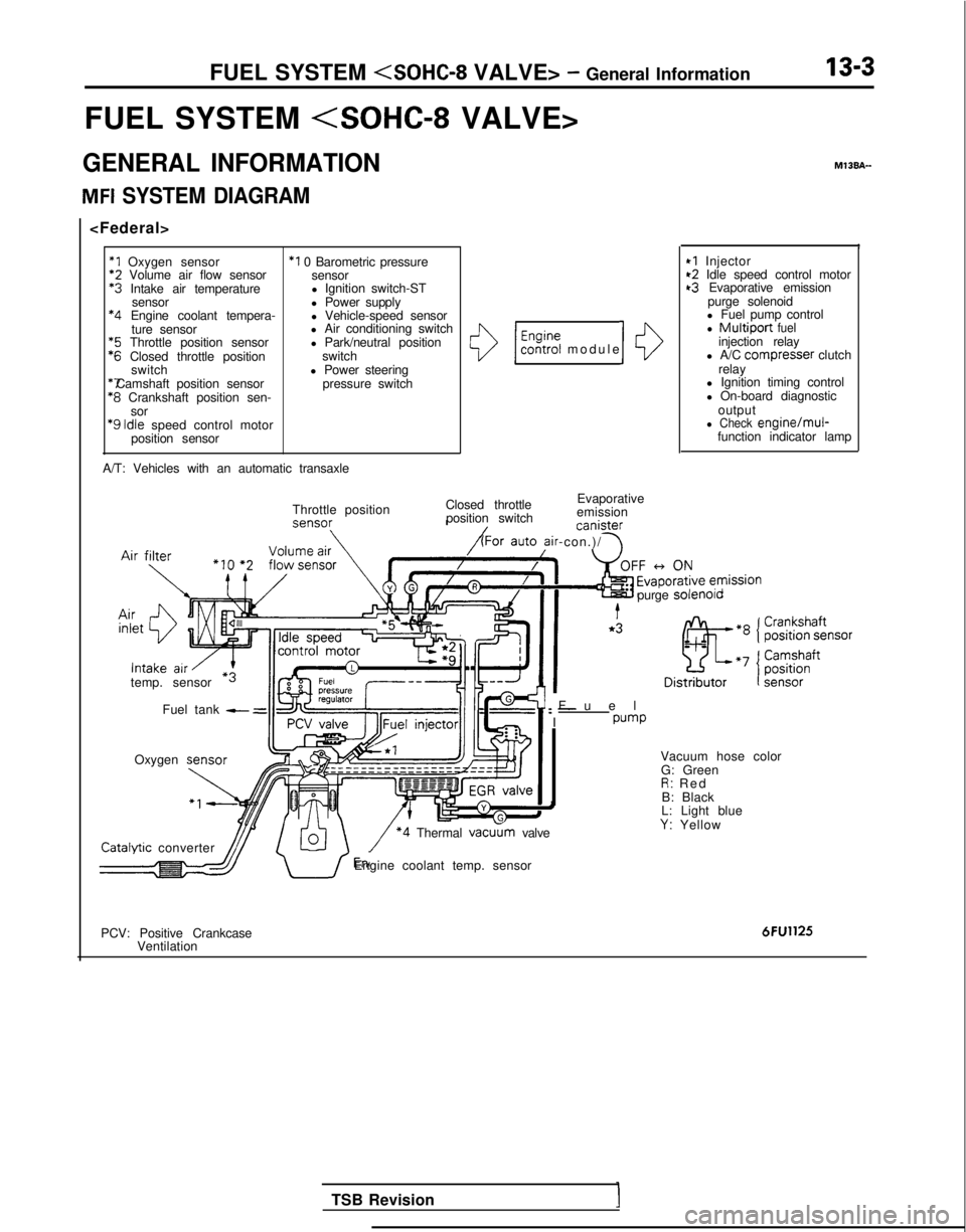
FUEL SYSTEM
FUEL SYSTEM
GENERAL INFORMATION
MFI SYSTEM DIAGRAM
*1 Oxygen sensor
*2
Volume air flow sensor *3
Intake air temperature
sensor *4
Engine coolant tempera-
ture sensor *5
Throttle position sensor *6
Closed throttle position
switch *7 Camshaft position sensor
*8
Crankshaft position sen-
sor
‘9 Idle
speed control motor
position sensor
*I 0 Barometric pressure sensor
l Ignition switch-ST
l Power supply
l Vehicle-speed sensor
l Air conditioning switch
l Park/neutral position
switch
l Power steering pressure switch
A/T: Vehicles with an automatic transaxle
()/ $%?i modul
e
Closed throttle Evaporative
position switch emission canister
ir-con.)/ \
10
Throttle position
temp. sensor Fuel tank
- =
Oxygen M13BA-
I
*I Injector~2 Idle speed control motort3 Evaporative emission
purge solenoid
l Fuel pump control
l Multiport fuelinjection relay
l A/C compresser clutch
relay
l Ignition timing control
l On-board diagnostic
output
l Check engine/mul-function indicator lamp
Fue
l
: -
I
pump
purge
solenolo Catalvtic
converter
\/ *4 Thermal vacu
G: Green
R: Re
d
B: Black
L: Light blue
Y: Yellow
dJJ/ U’Engine coolant temp. sensor
PCV: Positive Crankcase Ventilation
6FU1125
TSB Revision
Page 146 of 1273
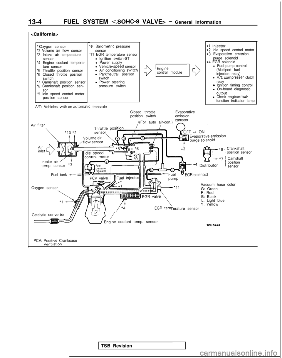
13-4FUEL SYSTEM
*2 Volume
air
flow sensor$3 Intake air temperature
sensor
*4 Engine coolant tempera-ture sensor
“5 Throttle position sensor‘6 Closed throttle position switch
*7 Camshaft position sensor*8 Crankshaft position sen-
sor
*9 Idle speed control motor position sensor “I 0
Barometric pressure
sensor
‘11 EGR temperature sensor
l Ignition switch-STl Power supply
l
Vehrcle-speed sensor
l Air conditioning switch
l Park/neutral position
switch
l Power steering pressure switchI13
Engrnecontrol module10
rl Injectort2 Idle speed control motorr3 Evaporative emission
purge solenoid
r4 EGR solenoidl Fuel pump control
(Multiport fuel
injection relay)
l A/C compresser clutchrelay0 Ignition timing control
l On-board diagnostic
output
l Check engine/muj-function indicator lamp
A/T: Vehicles
with an automatrc
transaxle
Closed throttleposition switch Evaporative
emission
/(For auto air-con.) can’ster
/ n
Vacuum hose
G: Green
R: Red
B: Black L: Light blue
Y: Yellow
erature sensor Air
filter
Fuel tank - =
Oxygen sensor
\ U /Eni coolant temp. sensor1FUO447
Crankshaft
position sensor
Camshaft
position
sensor
color
PCV: Posrtive
Crankcase
TSB Revision
Page 180 of 1273
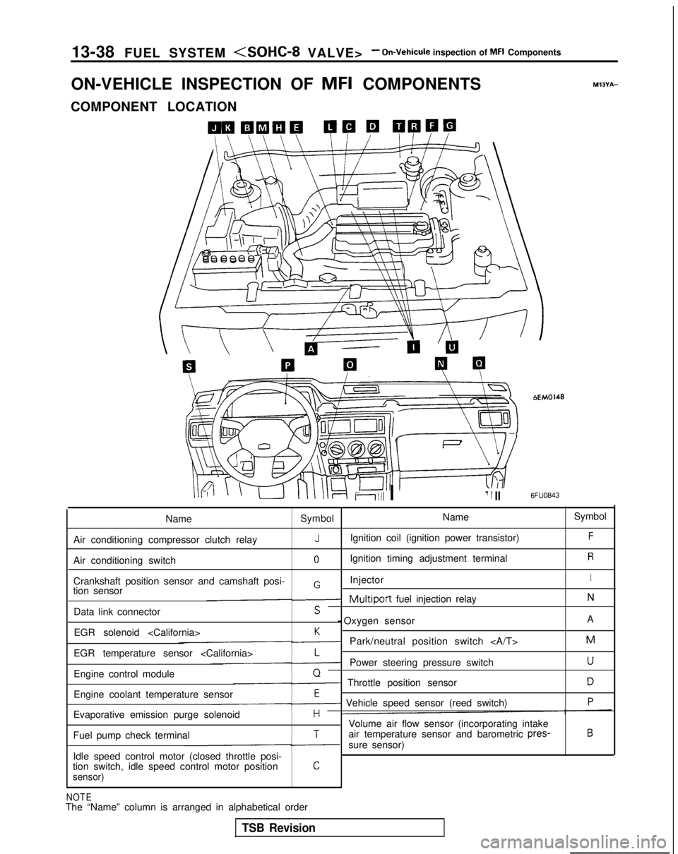
13-38
FUEL SYSTEM
ON-VEHICLE INSPECTION OF MFI
COMPONENTS
COMPONENT LOCATION
Ii111 I‘I 1 II
bEM0148
6FUO843
M?BYA-
Name Symbol Name
Symbol
Air conditioning compressor clutch relay
JIgnition coil (ignition power transistor)F
Air conditioning switch 0Ignition timing adjustment terminalR
Crankshaft position sensor and camshaft posi- InjectorIGtion sensor-Multiport fuel injection relayN
Data link connectorS - Oxygen sensor
A
EGR solenoid
K-Park/neutral position switch M
EGR temperature sensor
L-Power steering pressure switchU
Engine control moduleQ- Throttle position sensorD
Engine coolant temperature sensorE- Vehicle speed sensor (reed switch)P
Evaporative emission purge solenoidHVolume air flow sensor (incorporating intake
Fuel pump check terminalTair temperature sensor and barometric pres-B
-sure sensor)
Idle speed control motor (closed throttle posi-
tion switch, idle speed control motor position
Csensor)
NOTEThe “Name” column is arranged in alphabetical order
TSB Revision
Page 207 of 1273
FUEL SYSTEM
(1) Improper adjustment of the basic idling speed.
(2) Deposits adhering to the ttirottle valve.
(3) Air being taken into the intake manifold due to a gasket leak, etc.
OPERATION
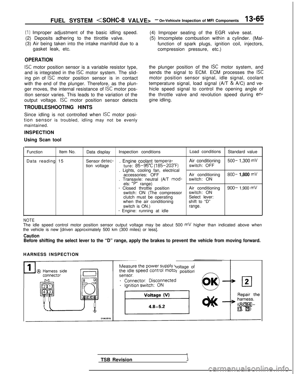
ISC motor position sensor is a variable resistor type,
and is integrated in the
ISC motor system. The slid-
ing pin of
ISC motor position sensor is in contact
with the end of the plunger. Therefore, as the plun- ger moves, the internal resistance of
ISC motor pos-
ition sensor varies. This leads to the variation of the (4) Improper seating of the EGR valve seat.
(5) lmcomplete combustion within a cylinder. (Mal-
function of spark plugs, ignition coil, injectors,
compression pressure, etc.)
the plunger position of the
ISC motor system, and
sends the signal to ECM. ECM processes the
ISC
motor position sensor signal, idle signal, coolant
temperature signal, load signal (A/T &
A/C) and ve-
hicle speed signal to control the opening angle of
the throttle valve and revolution speed during
en-
output voltage. ISC motor position sensor detects gine idling.
TROUBLESHOOTING HINTS
Since idling is not controlled when ISC motor posi-
tion sensor is troubled, idling may not be evenly
maintained.
INSPECTION
Using Scan tool
FunctionItem No. Data display Inspection conditions Load conditions
Standard value
Data reading 15 Sensor detec-
. Engine coolant tempera-
Air conditioning 500- 1,300 mV
tion voltage
ture: 85-95’C (185-203°F)
switch: OFF
. Lights, cooling fan, electrical accessories: OFF Air conditioning 800-
1,800 mV. Transaxle: neutral (A/T
mod-
switch: ON
els: “P”
range)
1 Closed throttle position Air conditioning900- 1,900 mVswitch: ON (The compressorswitch: ON
clutch must be operating Select lever:
when the air conditioning shift to “D”
switch is ON.)
range.* Engine: running at idle
NOTEThe idle speed control motor position sensor output voltage may be about\
500 mV higher than indicated above when
the vehicle is new [driven approximately 500 km (300 miles) or less].
CautionBefore shifting the select lever to the “D” range, apply the brake\
s to prevent the vehicle from moving forward.
HARNESS INSPECTION
Measure the power supply voltage of
the idle speed control motor position
ei;;;it;;sco$ected
__...._ -.-
TSB Revision
Page 225 of 1273
FUEL SYSTEM
inspection of MFI Components13-83
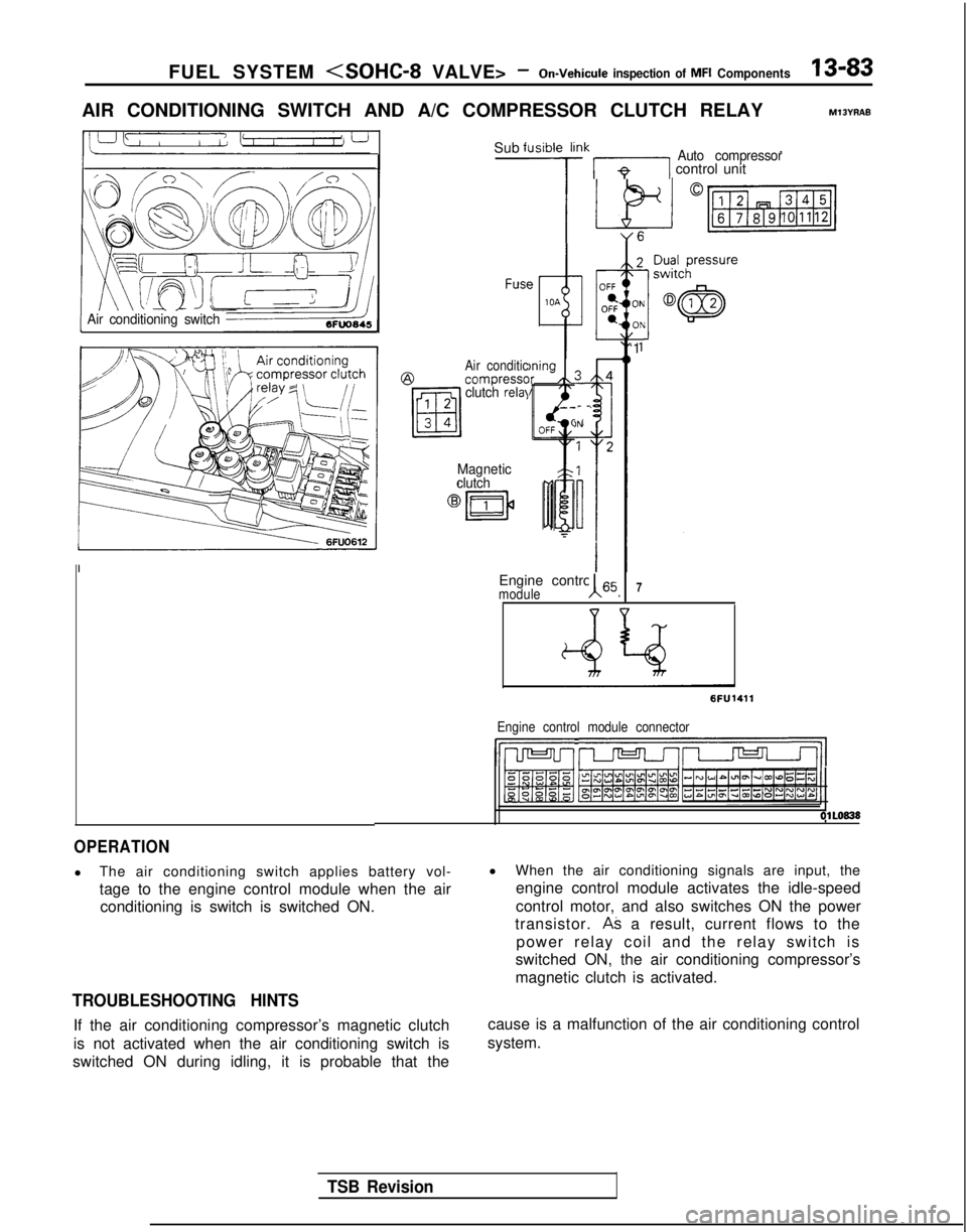
AIR CONDITIONING SWITCH AND A/C COMPRESSOR CLUTCH RELAYM13YRAE
Air conditioning switch
Sub fl
FUSC?
Air conditic@compresscclutch relal
Magnetic
clutch
Jsibie li
7
)ningIr /k
!Ik 171 control unitAuto compressor
-
-
)N
Engine control 65moduleA I7
‘1
6FU1411
Engine control module connector
IhJ-Jl r--vrJ=-Jl/l
OlLO838
OPERATION
l
The air conditioning switch applies battery vol-
tage to the engine control module when the air
conditioning is switch is switched ON.
TROUBLESHOOTING HINTS
If the air conditioning compressor’s magnetic clutch
is not activated when the air conditioning switch is
switched ON during idling, it is probable that the l
When the air conditioning signals are input, the
engine control module activates the idle-speed
control motor, and also switches ON the power
transistor.
AS a result, current flows to the
power relay coil and the relay switch is
switched ON, the air conditioning compressor’s
magnetic clutch is activated.
cause is a malfunction of the air conditioning control
system.
TSB Revision
Page 226 of 1273
13-84 FUEL SYSTEM
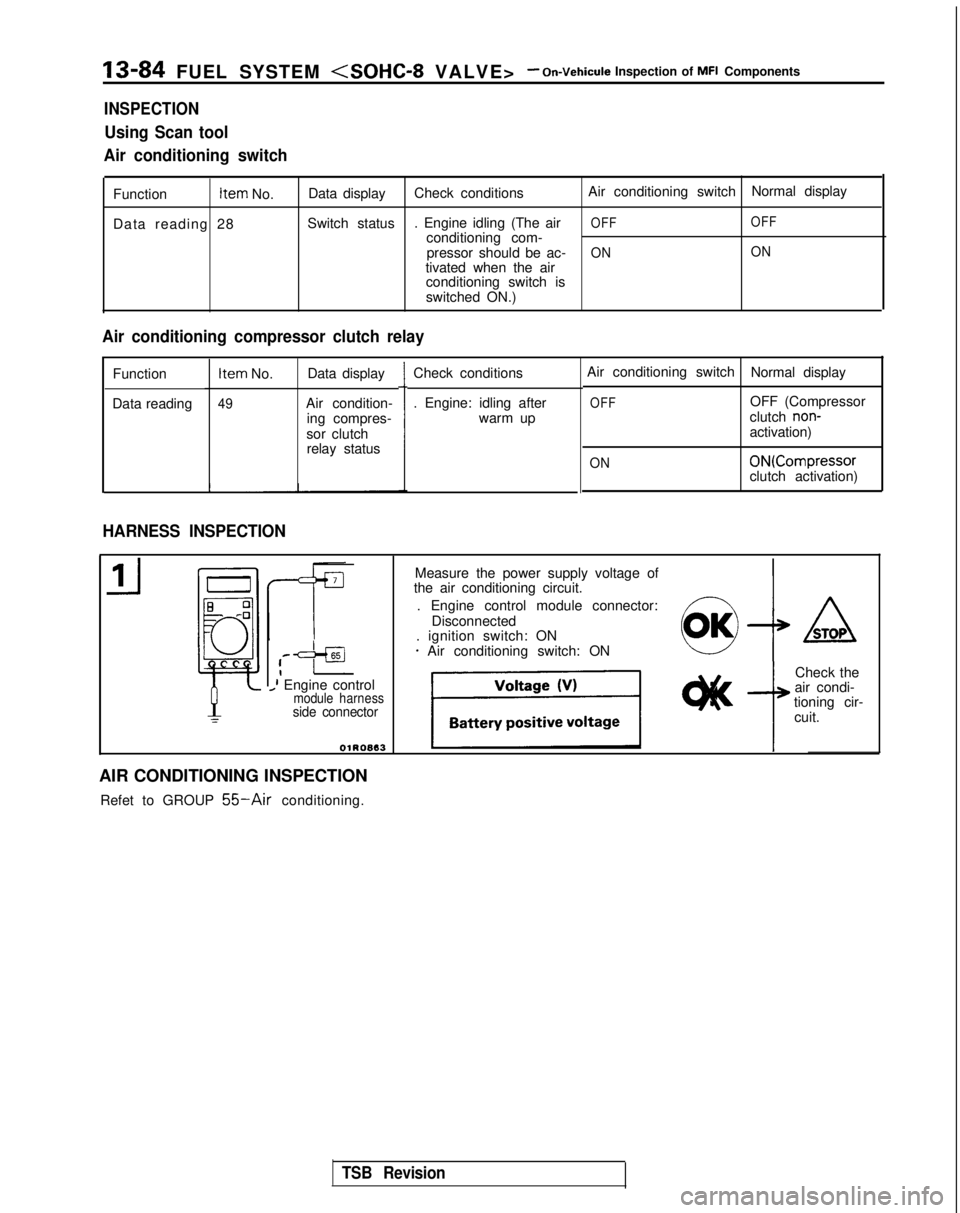
INSPECTION
Using Scan tool
Air conditioning switch
Function Item
No.
Data reading 28 Data display
Check conditions Air conditioning switch
Normal display
Switch status . Engine idling (The air
OFF OFFconditioning com-
pressor should be ac-ON ONtivated when the air
conditioning switch is
switched ON.)
Air conditioning compressor clutch relay
Function
Data reading Item
No. Data display
49Air condition-
ing compres-
sor clutch relay status Check conditions
. Engine: idling after
warm up
HARNESS INSPECTION
Air conditioning switch Normal display
OFFOFF (Compressor
clutch non-activation)
ON ON(Compressor
clutch activation)
,--=+aI_I Engine controlmodule harnessside connector
OlROB13
Measure the power supply voltage of
the air conditioning circuit.
. Engine control module connector: Disconnected
. ignition switch: ON
* Air conditioning switch: ON4
ASTOP
Check the
air condi-
tioning cir-
cuit.
AIR CONDITIONING INSPECTION Refet to GROUP
55-Air conditioning.
TSB Revision
Page 249 of 1273
FUEL SYSTEM
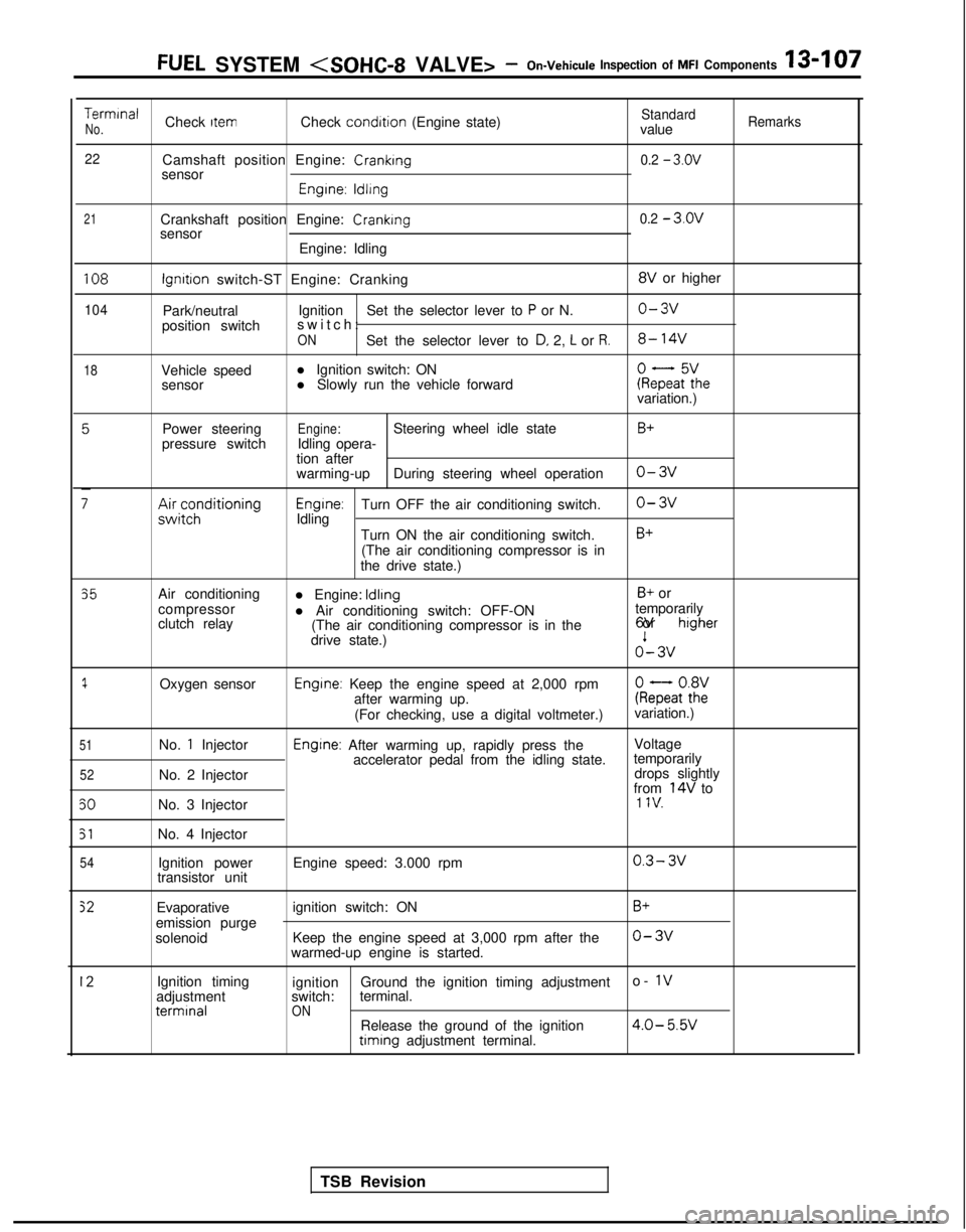
TerminalCheck ItemCheck condition
(Engine state)StandardNo.valueRemarks
22
Camshaft position Engine: Cranking0.2 - 3.ov
sensor
Engrne: ldllng
21Crankshaft position Engine: Crankingsensor
Engine: Idling0.2 - 3.ov
108
104
18
lgnrtron switch-ST Engine: Cranking 8V
or higher
Park/neutral Ignition
Set the selector lever to
P or N.o-3v
position switch switch
:
ONSet the selector lever to D, 2, L or R.8- 14V
Vehicle speed
l Ignition switch: ON
sensor l Slowly run the vehicle forwardkeFaF:hevariation.)
Power steering
pressure switch
;;ir;z;ditioning
Engine:Steering wheel idle state
Idling opera-
tion after
warming-up During steering wheel operation
Engrne:Turn OFF the air conditioning switch.
Idling
Turn ON the air conditioning switch.(The air conditioning compressor is in
the drive state.)
B+
o-3v
o-3v
B+
35
1
51
52
50
51
54
Air conditioning
compressor
clutch relay
Oxygen sensor
No.
1 Injector
No. 2 Injector
No. 3 Injector
No. 4 Injector Ignition power
transistor unit l Engine: Idling
B+ or
l Air conditioning switch: OFF-ON temporarily
(The air conditioning compressor is in the 6V or
higher
drive state.)o’- 3v
Engine: Keep the engine speed at 2,000 rpm
after warming up. kQatot8h2:
(For checking, use a digital voltmeter.) variation.)
Engine: After warming up, rapidly press the
Voltage
accelerator pedal from the idling state. temporarily
drops slightly
from
14V to1 IV.
Engine speed: 3.000 rpm0.3- 3v
Evaporative
emission purge
solenoid ignition switch: ON
Keep the engine speed at 3,000 rpm after the
warmed-up engine is started.B+
o-3v
12Ignition timing
adjustment terminal
ignition
Ground the ignition timing adjustment o- 1vswitch:
terminal.ONRelease the ground of the ignition4.0- 5.W timing
adjustment terminal.
TSB Revision