Page 380 of 1273
13-238FUEL SYSTEM - Troubleshooting
CIRCUIT DIAGRAM (CONTINUED)
FUSIBLE LINFsv
kJT0 COMPRESSORCONTROL UNIT
c-30 E
A-07-2X
$-231
IOD OR
~6oNFIK%OF
I
3
L2Ei
E
,234 C-37-l
J/B
MFIRELAY
Bkc-39
6A-07X
Els4
A-48
mA-08
I
AIRCONDITIONING
ENGINE COOLANT
g rfIi EFiTURE
@;j&FJQgQ'~.)
IB-22 I
103t%d, 1.
E
a 53c-10
V
B-05I J--
I
IMAGNETIC CLUTCH
MFI CONTROL UNITKX35-AC-HO53QB-NY
TSB Revision
Page 385 of 1273
FUEL SYSTEM - Troubleshooting
13-243
A-48
IEEl
Sl-
c-37-3,:
l&l
lx
1e34
MFIRELAYJ/Br
1
1
x
BSLHENOI D(VHEICLES FORCALIFORNIA)
2
&
53c-10
-
103
, BAWL”‘,
E2-J
G
I FUSIBLE LINb
C
0
10A
4A-07-2X
1
liizEa1234
IOD ORGTORAGE3CONNECTOR
2
1
2
AUTO COMPRESSOR
CONTROL UNIT
OF? N
i
!
%
#j;;y;,
(3OPSl)
0N:ZlOOhPa(29DPSi)OFF:2’i’OOkPa(384PS I)
I
[
MAGNET1 C CLUTCH
3
lh
B-05
Elle.3
=
MFI CONTROL UNIT
TSB Revision
Page 393 of 1273
Page 427 of 1273

FUEL SYSTEM -On-Vehicle Inspection of MFI Components13-285
AIR CONDITIONING SWITCH AND A/C COMPRESSOR CLUTCH RELAYmt3n7.4al
Jk: L 1 /J l-k~-~+ L!- Air conditioning switch
0
/’
’ ’ -~.i>
‘\ /,
(\ QeF --:
’ -q,,T
(‘a/ A-.,>*/ \
) !I/ ,+f---J;I’,,p
s- / :\,$jy W/’
\mc-- -; --
\\ \\$ &
IF -~1. bI /~-~ i E--z
\ \I i
!
L-,-1&L.- ~~~~.
6FUO845 I
Sub fusible link
‘7 IpI Z%37°GZressor
2 Dual pressure
switch
1
t
Air conditioning OFF
engif’Ie codant* temperatureON switc
h
T
2
TSB Revision
Engine control module
,(65 1\7
v v
Engine control module connector6FU1457
OlLo838
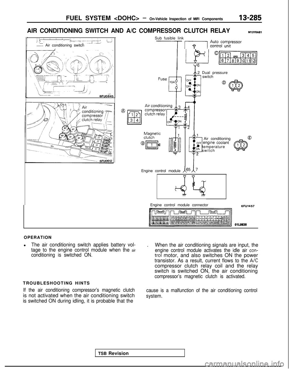
OPERATION
l
The air conditioning switch applies battery vol-
tage to the engine control module when the
air
conditioning is switched ON.
TROUBLESHOOTING HINTS
If the air conditioning compressor’s magnetic clutch
is not activated when the air conditioning switch
is switched ON during idling, it is probable that the
.When the air conditioning signals are input, the
engine control module activates the idle air con-
trol motor, and also switches ON the power
transistor. As a result, current flows to the A/C
compressor clutch relay coil and the relay
switch is switched ON, the air conditioning
compressor’s magnetic clutch is activated.
cause is a malfunction of the air conditioning control
system.
Page 428 of 1273
13-286FUEL SYSTEM - On-Vehicle Inspection of MFI Components
INSPECTION Using Scan tool
Air conditioning switch
Function Item No.
Data reading 28
Data displayCheck conditionsAir conditioning switchNormal
display
Switch status
. Engine idlingOFF OFF
(The air conditioning
compressor should beONONactivated when the air
conditioning switch is
switched ON.)
Air conditioning compressor clutch relay
Function
Item No.
Data reading 49
Data display
Check conditionsAir conditioning switchNormal display
Air condition-
. Engine: idling afterOFFOFF (Compressor
ing compres-warm up clutch non-
sor clutch
activation)
relay status ON
ONKompressorclutch activation)
HARNESS INSPECTION________ --- -__-. -- ~~-
Measure the power supply voltage of
the air conditioning circuit.
. Engine control module connec-tor: Disconnected- Ignition switch: ON+ Air conditioning switch: ON
side connector
AIR CONDITIONING INSPECTION
Refer to GROUP 55-Air Conditioning.
1 TSB RevisionI
Page 441 of 1273

FUEL SYSTEM -On-Vehicle Inspection of
MFI Components13-299
OPERATION
l The amount of air taken in during idling is
regulated by the opening and closing of the
servo valve located in the air passage that
bypasses the throttle valve.
l The servo valve is opened or closed by the
activation of the stepper motor (incorporated
within the idle air control motor) in the forward
or reverse direction.
TROUBLESHOOTING HINTS
Hint 1: If the number of stepper motor steps increases to
IOO- 120 steps or decreases
to 0 step, the cause may be presumed to be a malfunction of the stepper motor or
damaged or disconnected wiring of the
harness.
Hint 2: If the number of stepper motor steps
deviates from the standard value even
though the results of the checking of the
harness of the idle air control motor and of
the comoonent
itself indicate no abnormal
condition, the cause may be presumed to be one of the following.
INSPECTION
Using Scan tool
lBattery power supply is supplied, by way of the
multiport fuel injection relay, to the coil of the
stepper motor. The engine control module
switches ON the power transistors (located
within the engine control module) in sequential
order, and, when current flows to the stepper motor coil, the stepper motor is activated in the
forward or reverse direction.
(1) Improper adjustment of the standard
idling speed.
(2) Deposits adhered to the throttle valve.
(3) Leakage of air into the intake manifold
from a gasket gap, etc.
(4) Incomplete close contact of the EGRvalve seat.
(5) Incomplete combustion within the
cylinder.
(Malfunction of the spark plugs, the
ignition coil, the iniectors,
the
com- pression
pressure, etc.)
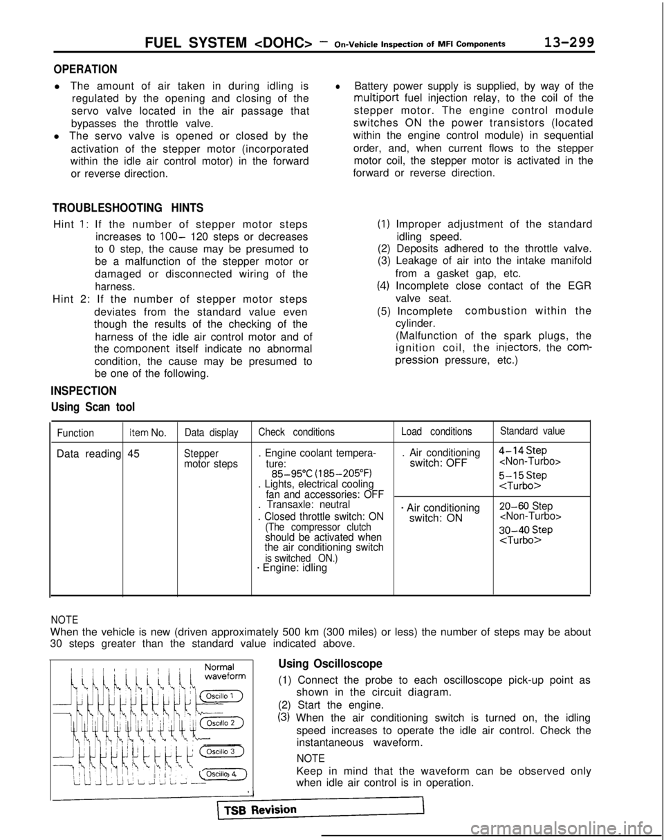
FunctionItem No.Data display Check conditions Load conditionsStandard value
Data reading 45Steppermotor steps. Engine coolant tempera-
. Air conditioning
4-14Step
ture:switch: OFF 85-95°C
(185-205°F)
. Lights, electrical cooling
:$b::pfan and accessories: OFF
. Transaxle: neutral
. Closed throttle switch: ON
- Air conditioning 20-60 Step
switch: ON
(The compressor clutchshould be activated when
the air conditioning switch;J-;;o~P
is switched ON.)* Engine: idling
1;:!,1;:!,
/!-I\/!-I\
f$&$:”f$&$:”
! ,‘,! ,‘,
4);4);
;jj\(Q(j!jGZ-);jj\(Q(j!jGZ-)
lili
q#Q~Hq#Q~HF]F]
ii 2 L J 2 L ~ -0SClllO 4ii 2 L J 2 L ~ -0SClllO 4
NOTE
When the vehicle is new (driven approximately 500 km (300 miles) or l\
ess) the number of steps may be about
30 steps greater than the standard value indicated above.
Using Oscilloscope
(1) Connect the probe to each oscilloscope pick-up point as
shown in the circuit diagram.
(2) Start the engine.
(3) When the air conditioning switch is turned on, the idling speed increases to operate the idle air control. Check theinstantaneous waveform.
NOTE
Keep in mind that the waveform can be observed only
when idle air control is in operation.
Page 458 of 1273

13-316FUEL SYSTEM -On-Vehicle
Inspection
of
MFI
Components
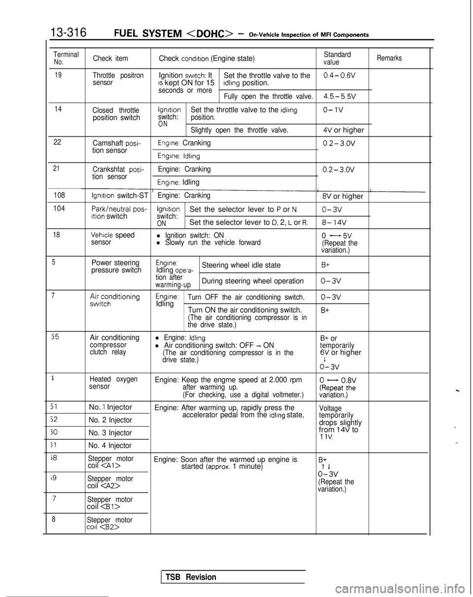
TerminalNo.Check itemCheck condition (Engine state)Standardvalue
Remarks
19Throttle positronIgnition switch: ItSet the throttle valve to the0.4- 0.wsensorIS kept ON for 15seconds or moreidlrng position.
Fully open the throttle valve.4.5- 5.5v
14
Closed throttlelgnrtrono-1vposition switchswitch:Set the throttle valve to the idling
position.
ONSlightly open the throttle valve.4V or higher
22Camshaft posi-tion sensorEngine: Cranking0.2- 3.ov
Engine: ldlrng
21
Crankshfat posi-tion sensor Engine: Cranking0.2- 3.ov
Engine: Idling
108lgnrtion switch-STEngine: Cranking8V or higher
104
Park/neutral
pos-ition switchIgnitionSet the selector lever to P or N.o-3vswitch:ONSet the selector lever to D, 2, L or R.8- 14V
18Vehicle speedl Ignition switch: ON
sensorl Slowly run the vehicle forward0 - 5v(Repeat the
variation.)
5Power steering
pressure switchEngine:Idling opera-Steering wheel idle stateB+
tion afterwarming-upDuring steering wheel operationo-3v
7A&;;;ditioningEngine:Idling _Turn OFF the air conditioning switch.o-3v
Turn ON the air conditioning switch.B+
(The air conditioning compressor is in
the drive state.)
35Air conditioningl Engine: IdlingB+ orcompressor
clutch relayl Air conditioning switch: OFF -, ON(The air conditioning compressor is in the
temporarily
drive state.)6V or higher o’-
3v
1Heated oxygen
sensorEngine: Keep the engrne speed at 2.000 rpmafter warming up.
(For checking, use a digital voltmeter.)ke;atoZivariation.)
51No. 1 InjectorEngine: After warming up, rapidly press the
52No. 2 Injector accelerator pedal from the idlrng state,Voltage
temporarily
drops slightly
30No. 3 Injectorfrom 14V to1 IV.
51No. 4 Injector
j8
Stepper motorcoil Engine: Soon after the warmed up engine isB+started (approx. 1 minute)
i9
Stepper motor0%
coil (Repeat the
variation.)
‘7Stepper motorcoil
8Stepper motorco11
TSB Revision
Page 474 of 1273

13-332
AUTO-CRUISE CONTROL SYSTEM - Specifications
AUTO-CRUISE CONTROL SYSTEM
SPECIFICATIONS
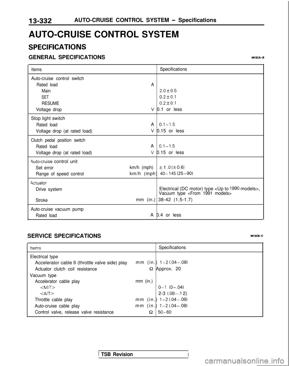
GENERAL SPECIFICATIONSM13CA--B
Items
Auto-cruise control switch
Rated load Main
SET
RESUME
Voltage drop
Stop light switch
Rated load
Voltage drop (at rated load)
Clutch pedal position switch
Rated load
Voltage drop (at rated load)
4uto-cruise control unit
Set errorRange of speed control
4ctuator
Drive system
Stroke
Auto-cruise vacuum pump
Rated load
Specifications
A
2.0f0.5
0.2fO.l 0.2t-0.1
V 0.1 or less
A
0.1-1.5
V 0.15 or less
A
0.1-1.5
V 0.15 or less
km/h (mph)IL 1 .O (kO.6)
km/h (mph) 40-145
(25-90)
Electrical (DC motor) type
1990 models>,Vacuum type
mm (in.) 38-42 (1.5-1.7)
A 0.4 or less
SERVICE SPECIFICATIONS
Ml3CB-.C
ItemsSpecifications
Electrical type
Accelerator cable B (throttle valve side) play mm (in.) l-2 (.04-.08)
Actuator clutch coil resistanceQ Approx. 20
Vacuum type
Accelerator cable play mm (in.)
O-l (O-.04)
Gv-r~2-3 (.08-.I 2)
Throttle cable playmm (in.) l-2 (.04-.08)
Auto-cruise cable playmm (in.) l-2
(.04-.08)
Control valve, release valve resistance52 50-60
1 TSB RevisionI