Page 545 of 1273
AUTO-CRUISE CONTROL SYSTEM - Service Adjustment procedures13-403
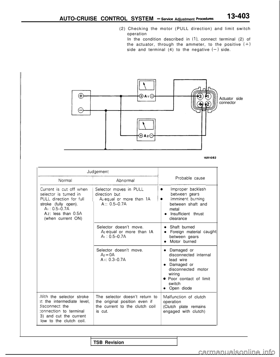
(2) Checking the motor (PULL direction) and limit switch
operation
In the condition described in
(1). connect terminal (2) of
the actuator, through the ammeter, to the positive
(+)
side and terminal (4) to the negative (-) side.
Actuator side
connector
16R1082
~1 L-E~~~~~~
stroke (fully open). A:: 0.5-0.7Abetween shaft andAI : 0.5-0.7Ametal
A Z: less than 0.5A
l Insufficient thrust
(when current ON) clearance
Selector doesn’t move. l Shaft burned Azequal
or more than IA l Foreign material
caugt
AI : 0.5-0.7Abetween gears
l Motor burned
Selector doesn’t move. Az=OA
A I:
0.3-0.7A
l Damaged or
disconnected internal
lead wire
l Damaged or disconnected motor
wiring
0 Poor contact of limit
switch
l Open diode
Nith the selector stroke The selector doesn’t return toMalfunciion of clutch3t the intermediate level,
the original position even if
operationdisconnect
the
the current to the clutch coil
(Clutch plate remains
:onnection to terminalis cut. engaged with clutch)
3) and cut the current
low to the clutch coil.
1t
TSB Revision
Page 547 of 1273

AUTO-CRUISE CONTROL SYSTEM - Sewice Adjustment Procedures
ECU connector terminals
19171513ll><7531
2018161412 101 98642
16A1060
ELECTRONIC CONTROL UNIT (ECU) SIGNAL CIRCUIT
CHECK
Disconnect the connector of the ECU, and then check at the
body side wiring harness according to the chart below.
IG SW: Ignition switch
MAIN SW: Main switch
OD SMI: Overdrive switch
Termi-~ Connection or mea-
nal
~
sured part Measure-
Tester con-
ment item nection
Check conditions
Standard
I-
I-
1 ~
Actuator (motor) Resistance1 - “‘2Actuator selector Approx. 120
(Fully closed position)
1
2
3I Stop light switchVoltage3-Ground ~
IG S/W ON, Main SW O
N
Battery positive
~
(for auto-cruise ~
control cancellation)
j )
i (Don’t press brake pedal.)j voltage
and actuator (clutch)I Press brake pedal after checkingBattery positive
5 1 Power supply (MAIN)
/ above.voltage -0V
Voltage5-Ground
1 IG S/W
ON, Main S/W ONBattery positive
voltage
6None-i -i-
7 1
Power supply (IGz)Voltag
e
7-GroundIG SfW O
N
Battery positive
voltage
8*z ~
On-board diagnostic--i- -
TSB Revision
9Accelerator pedal Voltageg-GroundIG SW O
N
Battery positive
switch
(Accelerator pedal free)voltage
1 Press accelerator pedal after/ Battery positive
II checking above.[voltage -0V
IO I Vehicle speed sensor
Voltage1 O-Ground’ W
ith the ignition key at the ON
’ ~
4 voltage
position, slowly turn the speedom- changes/
ca-
eter cable. ble
rotation
11SET switch
Continuity1 l-Ground ’ SET switch ON (Press) Continuity
SET switch OFF (Release) No continuity
12OD switch
13RESUME switch 1
Voltage
Continuity
12-GroundIG SNV ON OD SW ON position
Battery positive
voltage
OD
SW OFF position ~
OV
13-Ground ~
RESUME switch ON (Turn) Continuity
; RESUME switch OFF (Release)
No continuity
14’2 ~
4 A/T control module( -/- I- !
-
I/15 1 Stop light switch load
~
Voltage15-Ground’ Press the brake pedal.Battery positiveside/voltage
16 j Ground
Continuity1 16-GroundAt all times ~
Continuity
Page 548 of 1273
13-406AUTO-CRUISE CONTROL SYSTEM - Service A&tment ~mcec~ure~
Termi-
nal
17
18
19
20
l-
it
L
Connection of mea-
sured part Park/neutral position
switch (P, N)
T
f
+
Stop light switch
power supply side
Continuity ~
17-Ground
1
.~.~.~ ~.-. _ - ~~- -~/Voltage)
18-Ground
~~
____~ _~ ~.. ----+--.. .-~
Clutch pedal position
Voltage1 1 g-Groundswitch
Measure-1
Tester
ment item 1
connection
Ground
1 ~
Continuity ~
20-Ground
-Conrroljunitj I! @jIII LNOtOMl ‘-r’
+-j-
--J--L--
Actuator motor
03R0210
Check conditionsStandard
“P” or “N” rangeContinuity
Other than “P” or “N” range
,No continui-
v
At all timesj Battery positive
IG S/W
ON
Clutch pedal position switch OFF
At all times/ Continuity 1
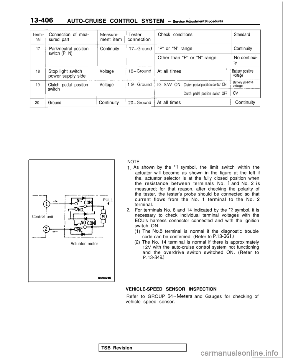
NOTE
1. As shown by the “1 symbol, the limit switch within the
actuator will become as shown in the figure at the left if
the. actuator selector is at the fully closed position when
the resistance between terminals No.
1 and No. 2 i
s
measured; for that reason, after checking the polarity of
the tester, the tester’s probe should be connected so that
current flows from the No. 1 terminal to the No. 2
terminal.
2.For terminals No. 8 and 14 indicated by the “2
symbol, it is
necessary to check individual terminal voltages with the
ECU’s harness connector connected and with the ignition
switch ON.
(1) The
No.8 terminal is normal if the diagnostic trouble
code can be confirmed. (Refer to
P.13-361.)
(2) The No. 14 terminal is normal if there is approximately
12V with the auto-cruise control system not functioning
and the overdrive switch switched ON. (Refer to
P. 13-349.)
VEHICLE-SPEED SENSOR INSPECTION
Refer to GROUP
54-Meters and Gauges for checking of
vehicle speed sensor.
TSB Revision
Page 550 of 1273
Page 551 of 1273
Page 651 of 1273
21-1
CLUTCH
CONTENTS
CLUTCH CONTROL. . . . . . . . . . . . . . . . . . . . . . . . . . . . . . . . . . . . \
. . . . .10SPECIFICATIONS. . . . . . . . . . . . . . . ..*...........................2
CLUTCHMASTER CYLINDER. . . . . . . . . . . . . . . . . . . . . . . .12GeneralSpecifications. . . . . . . . . . . . . . . . . . . . . . . . . . . . . . . . . .2
CLUTCH PEDALLubricants . . . . . . . . . . . . . . . . . . . . . . . . . . . . . . .\
. . . . . . . . . . . . . . . . . . . . . . .3. . . . . . . . . . . . . . . . . . . . . . . . . . . . . . . . . . . . \
. . . . . . . . . .7
ServiceSpecifications. . . . . . . . . . . . . . . . . . . . . . . . . . . . . . . . . . .2
CLUTCHRELEASECYLINDER. . . . . . . . . . . . . . . . . . . . . . .13Torque Specifications . . . . . . . . . .._.......................3
SERVICE ADJUSTMENT PROCEDURES . . . . . . . 5TROUBLESHOOTING. . . . . . . . . . . . . . . . . . . . . . . . . . . . . . . . . . . . \
. .4
Bleeding. . . . . . . . . . . . . . . . . . . . . . . . . . . . . . . .6Clutch chatters
Clutch Pedal Inspection and Adjustment . . . .
5Clutch noise
Clutch pedal feels “heavy”
Clutch slips
Gear shift malfunction
CAUTION When
servicing clutch assemblies or com-
ponents for vehicles with SOHC engine
(Up to 1991 models), do NOT create dust
by sanding or by cleaning clutch parts
with a dry brush or with compressed air.
(A water dampened cloth should be used).
The clutch disc contains “Asbestos Fibers”
which can become airborne if dust is
created during service operations. Breath-
ing dust containing “Asbestos Fibers”
may cause serious bodily harm.
Page 652 of 1273
21-2CLUTCH - Specifications
SPECIFICATIONS
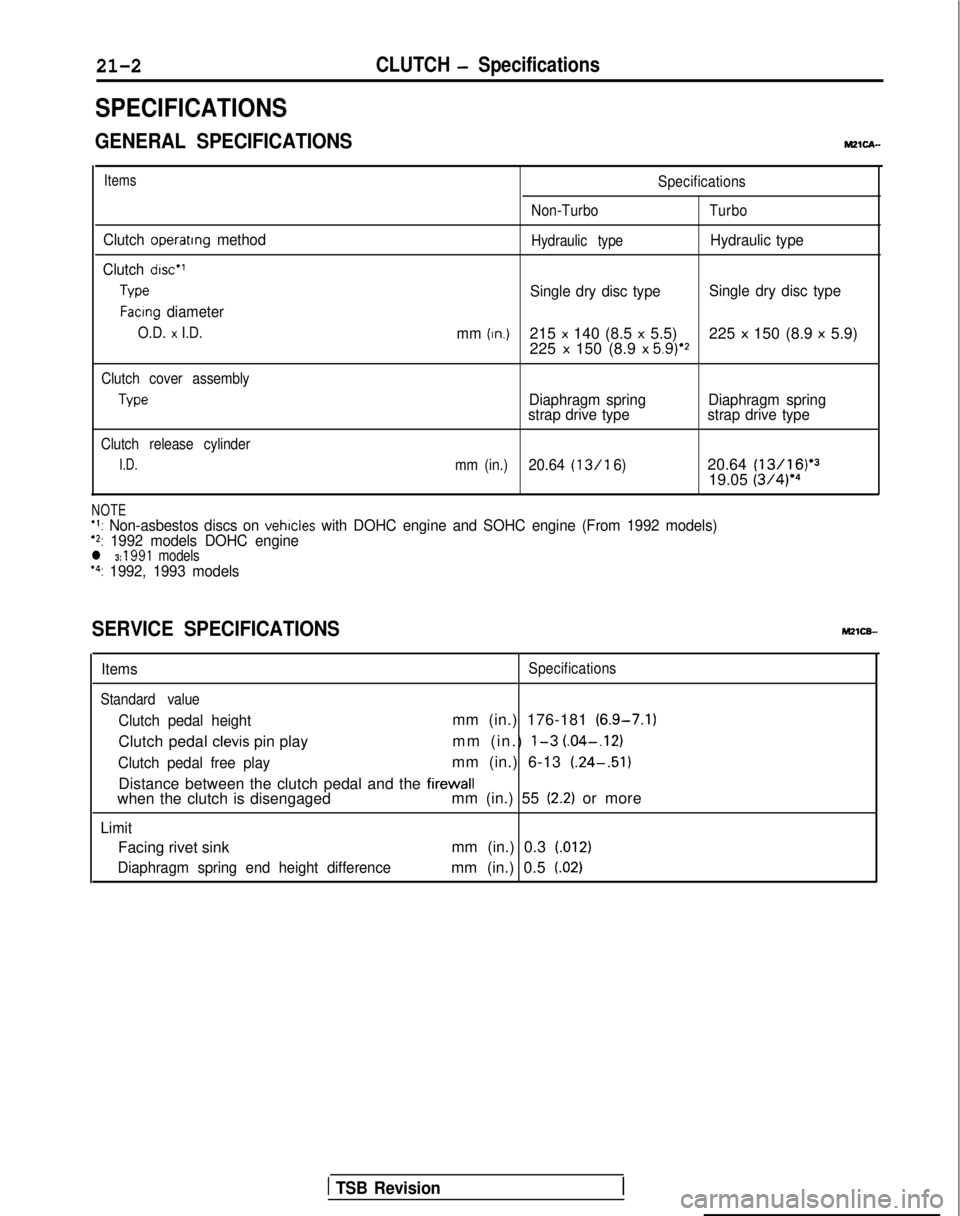
GENERAL SPECIFICATIONSMZlCA-
Items
Clutch operattng method
Clutch disc”
Type
Facing diameter
O.D. x I.D.
Specifications
Non-Turbo Turbo
Hydraulic type
Hydraulic type
Single dry disc type Single dry disc type
mm
(In.)215 x 140 (8.5 x 5.5) 225 x 150 (8.9 x 5.9)
225 x 150 (8.9 x 5.9)‘2
Clutch cover assembly
Type
Clutch release cylinder
I.D.
Diaphragm spring Diaphragm spring
strap drive type strap drive type
mm (in.)20.64 (13/l 6)20.64 (13/16)‘3
19.05 (3/4)‘4
NOTE+l: Non-asbestos discs on vehicles with DOHC engine and SOHC engine (From 1992 models)‘2: 1992 models DOHC enginel 3: 1991 models“: 1992, 1993 models
SERVICE SPECIFICATIONS
ItemsSpecifications
Standard value
Clutch pedal heightmm (in.) 176-181 (6.9-7.1)
Clutch pedal
clevis pin play mm (in.) l-3 (.04-.I21
Clutch pedal free playmm (in.) 6-13
(.24-.51)
Distance between the clutch pedal and the
firewallwhen the clutch is disengaged mm (in.) 55 (2.2) or more
Limit
Facing rivet sinkmm (in.) 0.3 1.012)
Diaphragm spring end height differencemm (in.) 0.5 f.02)
1 TSB Revision
Page 653 of 1273
CLUTCH - Specifications21-3
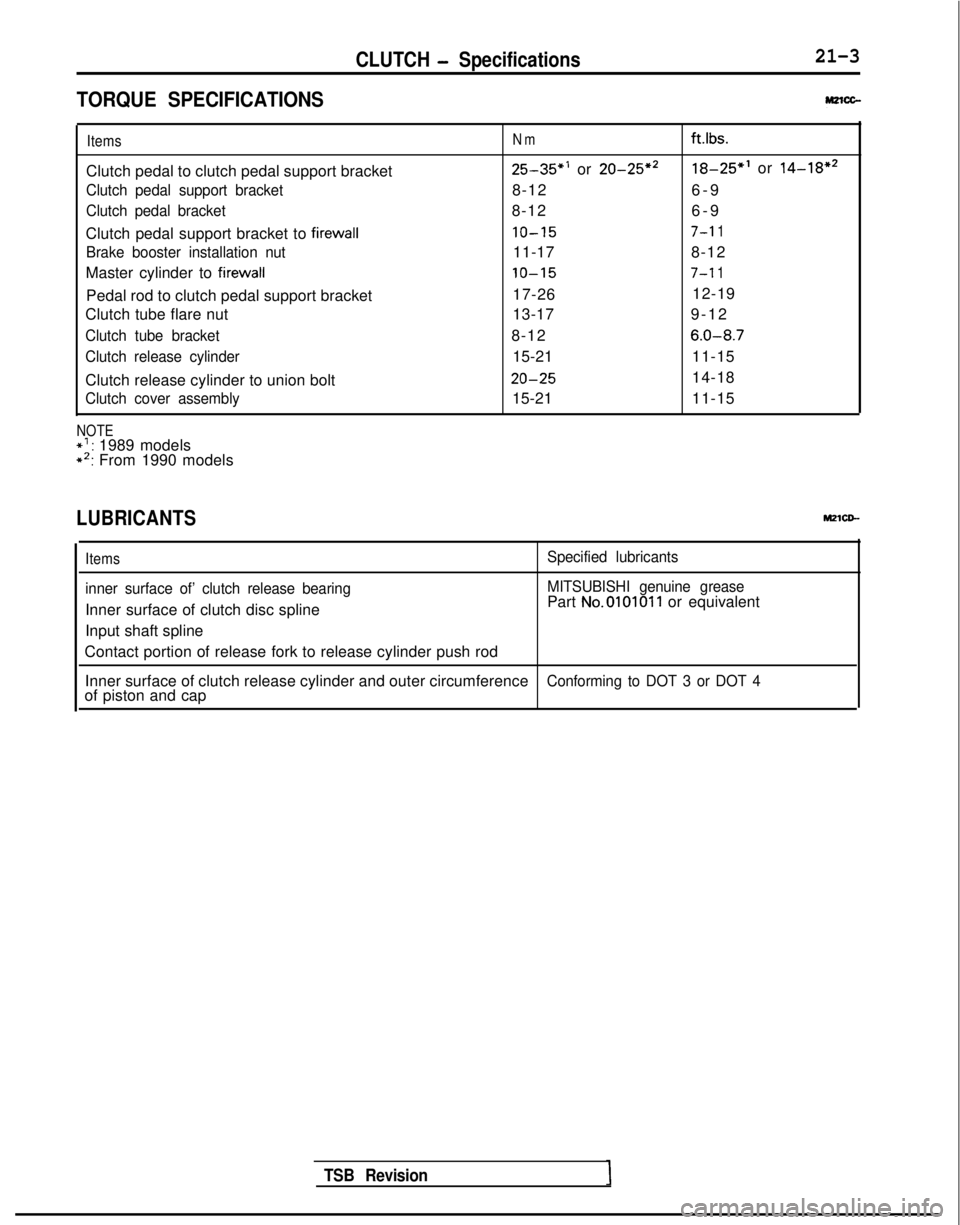
TORQUE SPECIFICATIONSM2lcc-
ItemsNmft.lbs.
Clutch pedal to clutch pedal support bracket25-35”’ or 20-25*218-25”’ or 14-18*2
Clutch pedal support bracket8-12
6-
9
Clutch pedal bracket8-12
6-
9
Clutch pedal support bracket to
firewall10-157-l 1
Brake booster installation nut11-17 8-12
Master cylinder to
firewall10-157-l 1
Pedal rod to clutch pedal support bracket 17-26
12-19
Clutch tube flare nut 13-179-1
2
Clutch tube bracket8-126.0-8.7
Clutch release cylinder15-21
11-15
Clutch release cylinder to union bolt
20-2514-18
Clutch cover assembly15-21 11-15
NOTE*’ : 1989 models*‘: From 1990 models
LUBRICANTSMZlCD-
Items
inner surface of’ clutch release bearing
Inner surface of clutch disc spline
Input shaft spline
Specified lubricants
MITSUBISHI genuine grease
Part No.010101 1 or equivalent
Contact portion of release fork to release cylinder push rod Inner surface of clutch release cylinder and outer circumference
Conforming to DOT 3 or DOT 4of piston and cap
TSB Revision