Page 500 of 1273
13-358AUTO-CRUISE CONTROL SYSTEM - Troubleshooting
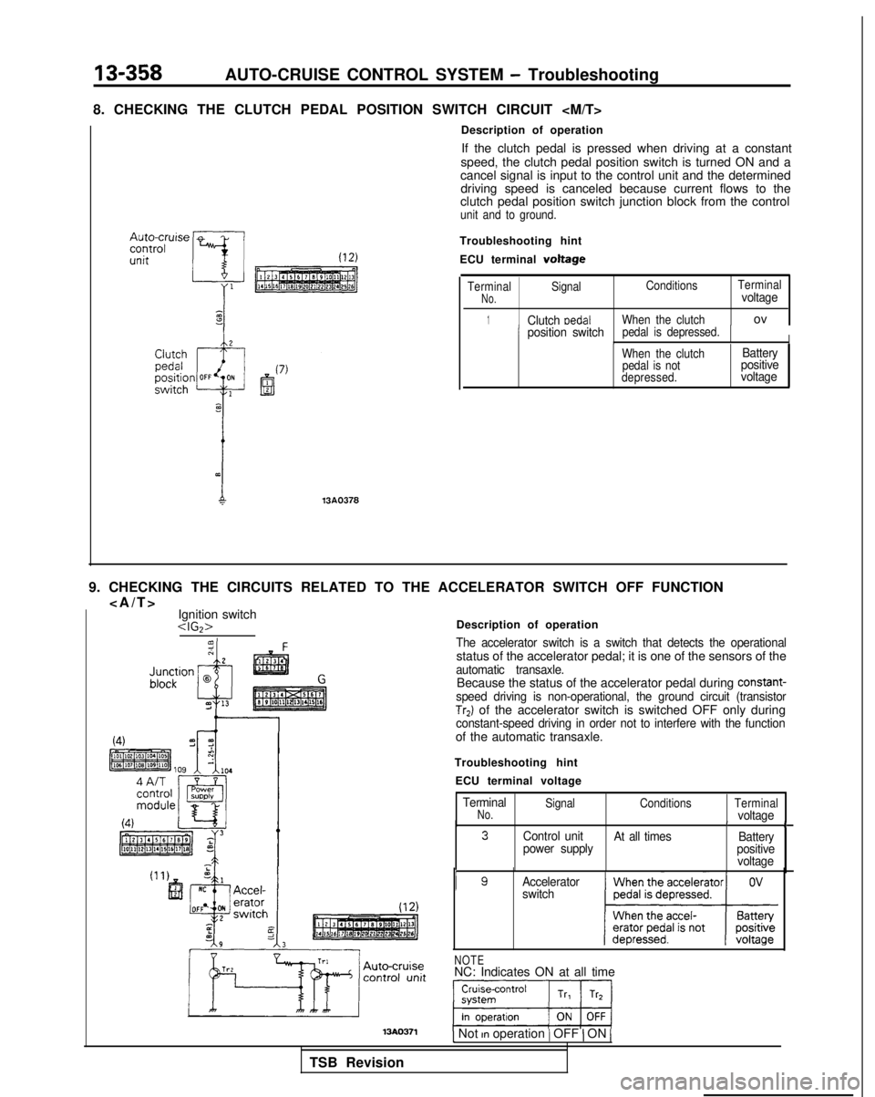
8. CHECKING THE CLUTCH PEDAL POSITION SWITCH CIRCUIT
13A0378
Description of operation If the clutch pedal is pressed when driving at a constant
speed, the clutch pedal position switch is turned ON and a
cancel signal is input to the control unit and the determined driving speed is canceled because current flows to the
clutch pedal position switch junction block from the control
unit and to ground.
Troubleshooting hint
ECU terminal
voltage
Terminal Signal Conditions
TerminalNo.voltage
1Clutch medalWhen the clutchov
Iposition switchpedal is depressed.IWhen the clutch
pedal is not
depressed.Battery
positive
voltage
9. CHECKING THE CIRCUITS RELATED TO THE ACCELERATOR SWITCH OFF FUNCTION
>
Ignition switch
The accelerator switch is a switch that detects the operationalstatus of the accelerator pedal; it is one of the sensors of theautomatic transaxle.Because the status of the accelerator pedal during constant-speed driving is non-operational, the ground circuit (transistorTr2) of the accelerator switch is switched OFF only duringconstant-speed driving in order not to interfere with the functionof the automatic transaxle.
Troubleshooting hint ECU terminal voltage
TerminalNo.Signal ConditionsTerminalvoltageII3Control unit
At all times Battery
power supply positive
voltage
I gAccelerator
switch
NOTENC: Indicates ON at all time
1 Not rn operation / OFF ) ON 1
TSB Revision
Page 506 of 1273
13-364AUTO-CRUISE CONTROL SYSTEM - Troubleshooting
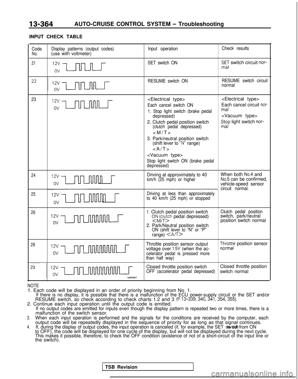
INPUT CHECK TABLE
Code Display patterns (output codes) Input operationCheck resultsNo.(use with voltmeter)
21SET switch ONSmE,: switch circuit nor-
RESUME switch ON RESUME switch circuit
normal
23
Each cancel switch ONEach cancel circuit nor-
1. Stop light switch (brake pedalmal
depressed)
2. Clutch pedal position switch(clutch pedal depressed)
St;p light switch nor-
>
3. Park/neutral position switch
(shift lever to “N” range)
>
Stop light switch ON (brake pedal
depressed)
24
25
n r
Driving at approximately to 40 When both No.4 and
km/h (25 mph) or higherNo.5 can be confirmed,
vehicle-speed sensor
circuit normal.
n r
Driving at less than approximately
to 40 km/h (25 mph) or stopped
26I. Clutch pedal position switchsNJFy;h pedal depressed)
2. Park/Neutral position switch
ON (shift lever to “N” or “P”
range)
Clutch pedal positionswitch, park/neutral position switch normal
28Throttle position sensor output
voltage over 1.5V (when the ac-celerator pedal is pressed more
than half way)
$yro;e position sensor
Closed throttle position switch Closed throttle position
OFF (accelerator pedal depressed)switch normal
NOTE1. Each code will be displayed in an order of priority beginning from No\
. 1.If there is no display, it is possible that there is a malfunction of th\
e ECU power-supply circuit or the SET and/orRESUME switch, so check according to check charts 1.2 and 3 (P.13-339,340,341,354,355).2. Continue each input operation until the output code is emitted.If no output codes are emitted for inputs even though the display patter\
n is repeated two or more times, there is amalfunction of the switch sensor.3.When each input operation is performed and the signals for the condition\
s are received by the computer, eachoutput code will be repeatedly displayed in the sequence of priority for\
as long as that signal continues.4.If, during the display of output codes, the input operation is canceled \
(if, for example, the SET switch is set from ONto OFF), the code will be displayed for one cycle of the display, but w\
ill not be displayed during the next cycle.This makes it possible, therefore, to check the OFF condition (existenc\
e of not of a short-circuit of the input line orthe switch).
TSB Revision
Page 507 of 1273
AUTO-CRUISE CONTROL SYSTEM - Troubleshooting13-365
AUTO-CRUISE CONTROL RELATED HARNESSES
16AO621
1 - Starter motor 7 - Clutch pedal position switch 14 - Overdrive switch2 - Park/neutral position switch8 - Column switch
15 - Control harness and body harness coupling
3 - Actuator , 9 - lgnrtion switch
16 - Control harness and body harness CouplingAuto-cruise pump10 - Stop light switch 17 - Diode 11 - Accelerator control unit16 - MFI control module4 - 4 A/T control module12 - Auto-cruise control unit
5
- Combination meter13 - On-board diagnostic output
6 - Combination meterterminal
TSB Revision
Page 515 of 1273
AUTO-CRUISE CONTROL SYSTEM - Troubleshooting13-373
CIRCUIT DIAGRAM
LINK@
1C-36
IGNITION SWITCH(IG1)SUB FUSIB
z
';,\7
c-43
J/B/t
6
15
6
CLUTCH PEDALI'f'+&ON
C-46
AUTO-CRUISE
CONTROL UNIT'
Y5^v
13
16 17
--- _--_-_
r;I1 ,*3
COLUMN SWITCH
AUTO-CRUISE CONTROL SWITCH
18
C-69
&J;T"igfUISE
ACTUATOR
iKl(3%AC-Hl535-NY
1 TSB Revision
Page 520 of 1273
13-378AUTO-CRUISE CONTROL SYSTEM - Troubleshooting
CIRCUIT DIAGRAM
aEiI
3 C-36
1
7
IGNITION
2
(1
J/E!I@
IIOA
z7
c-39
UTO-CRUISE
ONTROL UNIT “12
”z 1
q2
CLUTCH
@&ON/1
3C-46 OFT -,:o\I
-.E!
IY
I
I.------e-J1
COLUMN EWITCH
AUTO-CRUIGB
CONTROL SWITCH
13.
I
4_----c-07- 1
3
a:I
I
5Im-1
TSB Revision
Page 540 of 1273
13-398
AUTO-CRUISE CONTROL SYSTEM - Setice Adjustment procedures
03*02.5*
1
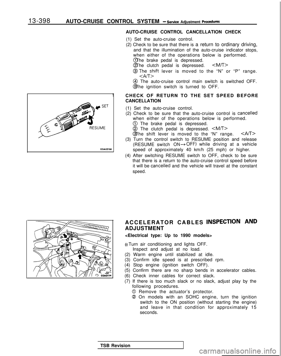
AUTO-CRUISE CONTROL CANCELLATION CHECK
(1) Set the auto-cruise control.
(2) Check to be sure that there is a return to ordinary driving,
and that the illumination of the auto-cruise indicator stops,
when either of the operations below is performed. @ The brake pedal is depressed.
@ The clutch pedal is depressed.
@ TJhEzift lever is moved to the “N” or “P” range.
@I The auto-cruise control main switch is switched OFF.
@ The ignition switch is turned to OFF.
CHECK OF RETURN TO THE SET SPEED BEFORE
CANCELLATION (1) Set the auto-cruise control.
(2) Check to be sure that the auto-cruise control is
cancelled
when either of the operations below is performed.
@ The brake pedal is depressed.
@ The clutch pedal is depressed. @ The shift lever is moved to the “N” range.
CAST>
(3) Turn the control switch to RESUME position and release
(RESUME switch
ON*OFF) while driving at a vehicle
speed of approximately 40 km/h (25 mph) or higher.
(4) After switching RESUME switch to OFF, check to be sure that there is a return to the auto-cruise control speed before
it will be
cancelled and the vehicle will travel at the constant
speed.
ACCELERATOR CABLES INSPECTION AND
ADJUSTMENT
(I) Turn air conditioning and lights OFF. Inspect and adjust at no load.
(2) Warm engine until stabilized at idle.
(3) Confirm idle speed is at prescribed rpm.
(4) Stop engine (ignition switch OFF).
(5) Confirm there are no sharp bends in accelerator cables.
(6) Check inner cables for correct slack.
(7) If there is too much slack or no slack, adjust play by the following procedures.
0 Remove the actuator’s protector.
0 On models with an SOHC engine, turn the ignition
switch to the ON position (without starting the engine)
and leave in that condition for approximately 15
seconds.
TSB Revision
Page 543 of 1273
AUTO-CRUISE CONTROL SYSTEM - Setice Adiustment Procedures13-401
16AO192
--
Ib/-
SJy-
iii
3 1
24
J
14LO142
INDIVIDUAL PARTS INSPEtiTION
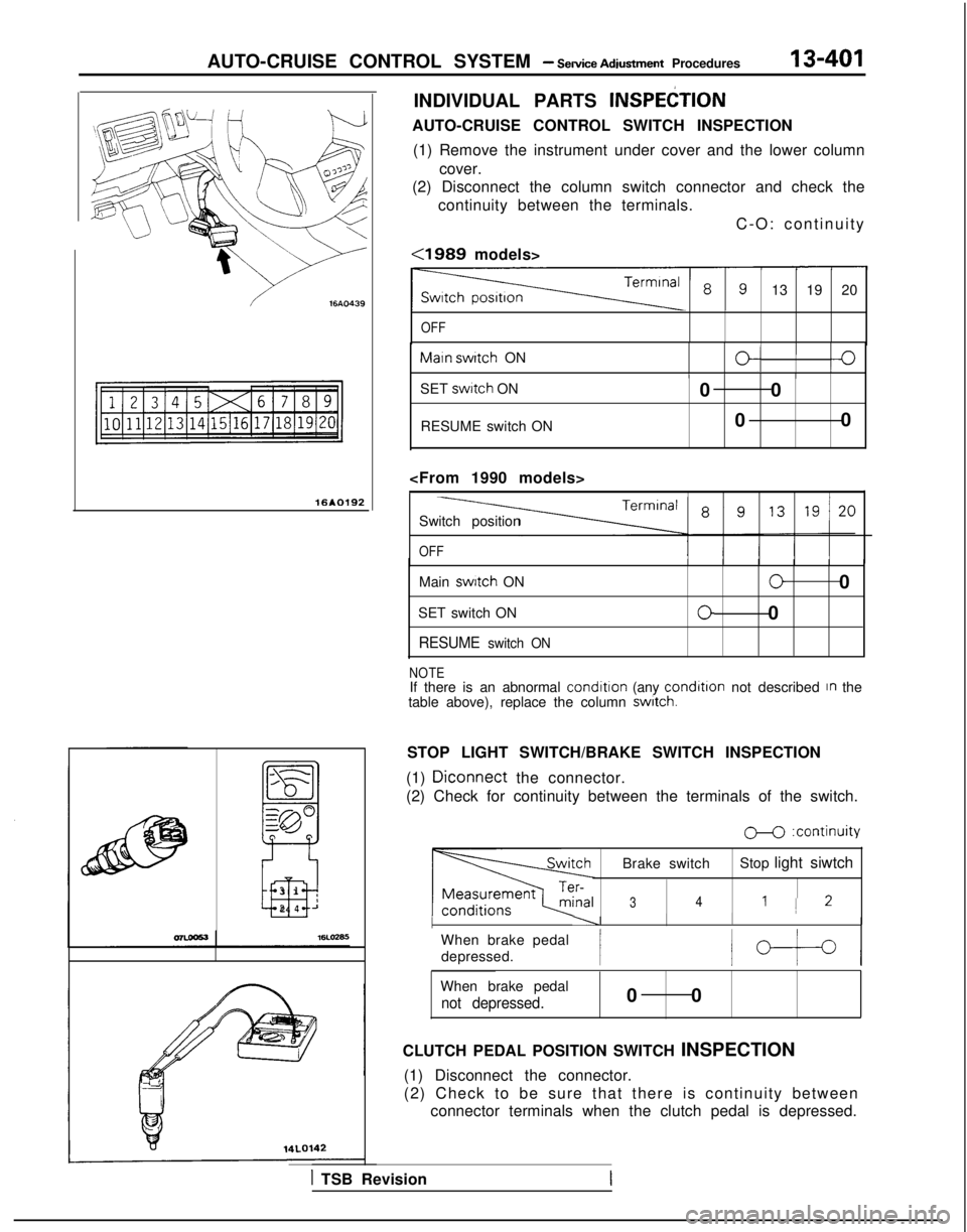
AUTO-CRUISE CONTROL SWITCH INSPECTION
(1) Remove the instrument under cover and the lower column cover.
(2) Disconnect the column switch connector and check the
continuity between the terminals.
C-O: continuity
<1989 models>
13 19 20
OFF Maln
switch
ON
O/I0IIIISET swttch
ON
RESUME switch ON 0 0
0 0
Switch position
OFF
Main switch
ON
SET switch ON
RESUME switch ON
00
00
NOTEIf there is an abnormal condition
(any condltlon
not described In the
table above), replace the column switch.
STOP LIGHT SWITCH/BRAKE SWITCH INSPECTION
(1)
Diconnect the connector.
(2) Check for continuity between the terminals of the switch.
M :continuity
Brake switch Stop light siwtch
341 1 2
I----II I
When brake pedal
depressed.
/b-t-4
When brake pedal
not depressed.0 0
CLUTCH PEDAL POSITION SWITCH INSPECTION (1) Disconnect the connector.
(2) Check to be sure that there is continuity between connector terminals when the clutch pedal is depressed.
1 TSB Revision
Page 544 of 1273
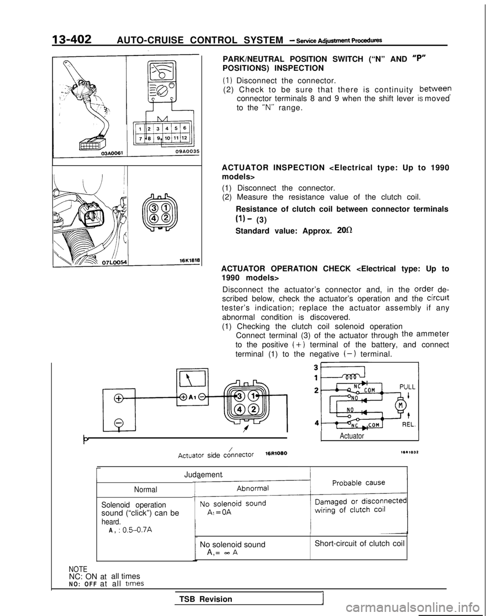
13-402AUTO-CRUISE CONTROL SYSTEM - service Adjusbnent PWSXIU~S
PARK/NEUTRAL POSITION SWITCH (“N” AND “P”
POSITIONS) INSPECTION
(1) Disconnect the connector.
(2) Check to be sure that there is continuity ,between
connector terminals 8 and 9 when the shift lever IS moved
to the “N”
range.
ACTUATOR INSPECTION
(1) Disconnect the connector.(2) Measure the resistance value of the clutch coil.
Resistance of clutch coil between connector terminals
(1) - (3)
Standard value: Approx.
2Ofl
ACTUATOR OPERATION CHECK
Disconnect the actuator’s connector and, in the
ordey de-
scribed below, check the actuator’s operation and the clrcult
tester’s indication; replace the actuator assembly if any
abnormal condition is discovered.
(1) Checking the clutch coil solenoid operation Connect terminal (3) of the actuator through the
ammeter
to the positive
(+) terminal of the battery, and connect
terminal (1) to the negative
(-) terminal.
Actuator
Actuator side cO/nectOr16R10801SR1032
rJudaement
Normal
Solenoid operation
sound (“click”) can be
heard.
T
-t
A, : 0.5-0.7A
NOTENC: ON at all times No solenoid sound
A,=
mA
Short-circuit of clutch coil
NO: OFF at all
times
TSB RevisionI