Page 662 of 1273
21-12CLUTCH - Clutch Master Cylinder
CLUTCH MASTER CYLINDER
DISASSEMBLY AND REASSEMBLY
MZlNA-
Disassembly steps
1. ‘Piston stop ring2.Push rod3.Boot
*I)4. Piston assembly5.Reservoircap6.Reservoirband7.Reservoir8. Master cylinder body
08AOO34
Brake Fluid: Conforming to DOT3or DOT4
SERVICE POINTS OF DISASSEMBLYMZlNBAC
4. REMOVAL OF PISTON ASSEMBLY
Caution
1.Do not damage the master cylinder body and piston
assembly.
2. Do not disassemble piston assembly.
\\08AOOi4
INSPECTIONM21NcAc
l Check the inside cylinder body for rust or scars.
l Check the piston cup for wear or deformation.
l Check the piston for rust or scars.
l Check the clutch tube connection part for clogging.
TSB Revision
Page 663 of 1273
CLUTCH - Clutch Release Cylinder
CLUTCH RELEASE CYLINDER
{EMOVAL AND INSTALLATION
Pre-removal Operationl Draining of the clutch fluidl Bleeding of the clutch line (Refer
Release cylinder O(Ivl,,push rod
TSB Revision1
20-25 Nm
Removal steas
1. Clutch tube
2. Union
3. Clutch release cylinder
INSPECTIONm21ncAA
l Check the clutch release cylinder for fluid leakage.
l Check the clutch release cylinder boots for damage.
Page 666 of 1273
22-2MANUAL TRANSAXLE
- Specifications
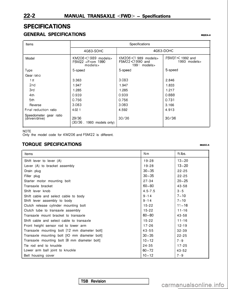
SPECIFICATIONS
GENERAL SPECIFICATIONSMZXA-A
ItemsSpecifications 4G63-SOHC 4G63-DOHC
Model KM206
<1989 models> KM206
F5M31 < 1992 and F5M22
<1990 and 1993 models>
models> 1991models>
Type5-speed5-speed 5-speed
Gear ratio
1 St3.363
3.083
2.8462nd
1.947 1.947 1.8333rd
1.285 1.285 1.2174th
0.9390.9390.888
5th0.7560.756
0.731
Reverse
3.083 3.083
3.166
Frnal reductron
ratio4.02 14.592 4.913
Speedometer gear ratio (driven/drive)
2913630/3630/36 (30/36
. 1993 models only)
NOTEOnly the model code for KM206 and F5M22
is different.
TORQUE SPEClFlCATiONSMUCC-A
ItemsNmftlbs.
Shift lever to lever (A) 19-2813-20
Lever (A) to bracket assembly19-2813-20
Drain plug30-3522-25
Filler plug
30-3522-25
Starter motor mounting bolt 27-34
20-25
Transaxle bracket60-8043-58
Shift lever knob 4.5-7.53-
5
Shift cable and select cable to body 9-14
7-10
Shift lever assembly to body
9-1
4
7-10
Clutch release cylinder mounting bolt
15-2211-16
Clutch tube to transaxle assembly15-2211-16
Transaxle mount bracket to transaxle
60-8043-58
Shift cable and select cable to transaxle 15-2211-16
Front height sensor rod to lower arm 17-2612-19
Transaxle mounting bolt
[I2 mm diameter bolt] 43-5
5
32-39
Transaxle mounting bolt [IO mm diameter bolt]
30-3522-25
Transaxle mounting bolt
[8 mm diameter bolt]IO-127-
9
Tie rod end to knuckle 24-3517-25
Lower arm ball joint to knuckle
60-7243-52
Bell housing cover
10-127-
9
TSB Revision
Page 671 of 1273
MANUAL TRANSAXLE
- Transaxle Control22-7
ect- cable\
I Lever
(B)
09A0160
IIncorrect-I I
SERVICE POINTS OF INSTALLATIONM22JDAK
6. INSTALLATION OF SELECT CABLE
(1) Move the transaxle shift lever to the neutral position.
NOTE
The select lever will be set to the neutral position when
the transaxle shift lever is moved to the neutral position.
(2) Move lever
(B) to the neutral position.
(3) Adjust, by using the adjuster, so that the end of the select cable is positioned as shown in the illustrationrelative to lever
(B).
(4) The flange side of the resin bushing at the select cable end should be at the lever
(B) end surface.
5. INSTALLATION OF SHIFT CABLE
(1) With the select lever in neutral, move the transaxle shiftlever (in the direction shown in the illustration) to set it
to 4th
gear.
NOTE
If the shift lever does not move easily, depress and hold
the clutch pedal.
1 TSB Revision
Page 674 of 1273
22-10MANUAL TRANSAXLE - Transaxl
e
TRANSAXLE
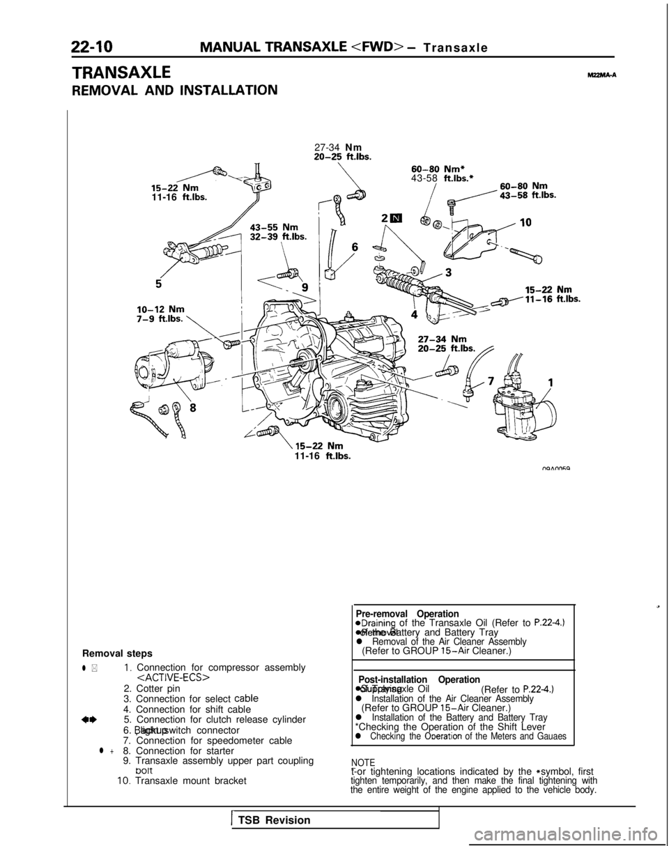
REMOVAL AND INSTALLATION
MZMA-A
27-34 Nm20-25 ft.lbs.
60-80
Nm*
43-58 ft.lbs.*
11-16
ft.lbs.71
11-16 ftlbs.
Removal steps
l *1, Connection for compressor assembly
2. Cotter pin
3. Connection for select cable
4. Connection for shift cable
a*5. Connection for clutch release cylinder
6. backup light switch connector
7. Connection for speedometer cable
l +8. Connection for starter
9. Transaxle assembly upper part coupling
tJ01t10. Transaxle mount bracket
Pre-removal Operation@Draining of the Transaxle Oil (Refer to P.22-4.) *Removal of the Battery and Battery Tray
l Removal of the Air Cleaner Assembly(Refer to GROUP 15-Air Cleaner.)
Post-installation Operation
asupplying of Transaxle Oil
(Refer to P.224.)l Installation of the Air Cleaner Assembly(Refer to GROUP 15-Air Cleaner.)l Installation of the Battery and Battery Tray*Checking the Operation of the Shift Leverl Checking the Ooeration of the Meters and Gauaes
NOTE
-t-or tightening locations indicated by the * symbol, firsttighten temporarily, and then make the final tightening with
the entire weight of the engine applied to the vehicle body.
1TSB Revision
Page 676 of 1273
22-12MANUAL TRANSAXLE
- Transaxle
* ’TransaxlellK611I-I-1 TSB Revision
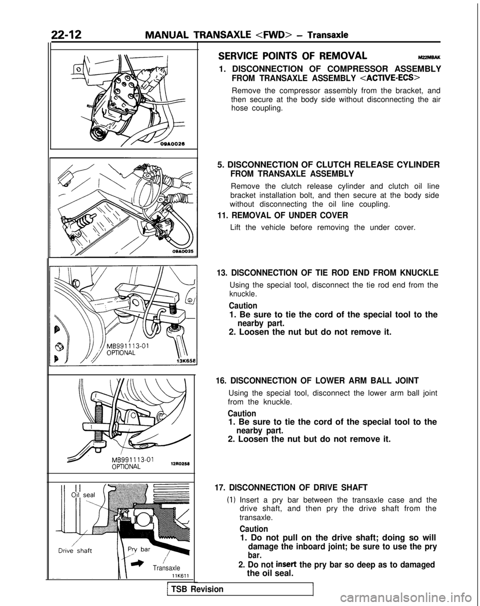
SERVICE POINTS OF REMOVALM22MBAK
1. DISCONNECTION OF COMPRESSOR ASSEMBLY
FROM TRANSAXLE ASSEMBLY
Remove the compressor assembly from the bracket, and
then secure at the body side without disconnecting the air hose coupling.
5. DISCONNECTION OF CLUTCH RELEASE CYLINDER
FROM TRANSAXLE ASSEMBLY
Remove the clutch release cylinder and clutch oil line
bracket installation bolt, and then secure at the body side
without disconnecting the oil line coupling.
11. REMOVAL OF UNDER COVER
Lift the vehicle before removing the under cover.
13. DISCONNECTION OF TIE ROD END FROM KNUCKLE
Using the special tool, disconnect the tie rod end from the
knuckle.
Caution
1. Be sure to tie the cord of the special tool to the
nearby part.
2. Loosen the nut but do not remove it.
16. DISCONNECTION OF LOWER ARM BALL JOINT
Using the special tool, disconnect the lower arm ball joint
from the knuckle.
Caution
1. Be sure to tie the cord of the special tool to the
nearby part.
2. Loosen the nut but do not remove it.
17. DISCONNECTION OF DRIVE SHAFT
(1) Insert a pry bar between the transaxle case and the drive shaft, and then pry the drive shaft from the
transaxle.
Caution
1. Do not pull on the drive shaft; doing so will
damage the inboard joint; be sure to use the pry
bar.
2. Do not insert the pry bar so deep as to damaged
the oil seal.
Page 679 of 1273
MANUAL TRANSAXLE - SDecifications2245
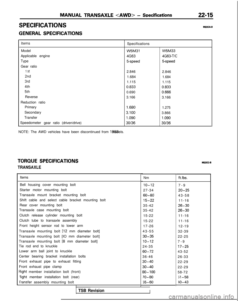
SPECIFICATIONSM?zcA-B
GENERAL SPECIFICATIONSItems
Specifications
Model W5M31
Applicable engine 4G63
Tvw
5-speed
Gear ratio
1 St2.846
2nd1.684
3rd1.115 4th
0.833
5th
0.690
Reverse 3.166
Reduction ratio Primary
1.680
Secondary 3.100
Transfer
1.090
Speedometer gearratio(driven/drive)30136
NOTE: The AWD vehicles have been discontinued from 1993 models. W5M33
4G63-TIC
5-speed
2.846
1.684
1.115
0.833 0.666
3.166
1.275
3.866
1.090
30136
TORQUE SPECIFICATIONS
TRANSAXLE
Items
Bell housing cover mounting bolt
10-127-
9
Starter motor mounting bolt 27-34
20-25
Transaxle mount bracket mounting bolt60-8043-5
8
Shift cable and select cable bracket mounting bolt
15-2211-16
Rear cover mounting bolt 35-42
26-30
Transaxle case mounting bolt 35-4226-30
Clutch release cylinder mounting bolt 15-2211-16
Clutch tube to transaxle assembly 15-2211-16
Front height sensor rod to lower arm 17-2612-19
Transaxle mounting bolt
[I2 mm diameter bolt] 43-5
5
32-39
Transaxle mounting bolt [IO mm diameter bolt]
30-3522-25
Transaxle mounting bolt
18 mm diameter bolt]IO-127-
9
Tie rod end to knuckle 24-35
17-25
Lower arm ball joint to knuckle60-7243-52
Center bearing bracket installation bolts 36-4626-33
Front exhaust pipe to exhaust fitting
30-4022-29
Front exhaust pipe clamp
30-4022-29
Right member installation bolt (front)30- 10058-72
qight member installation bolt (rear)70-80jl-58 rransfer
assembly mounting bolt
55-60IO-43
Nm M22CGBft.lbs.
TSB RevisionI
Page 680 of 1273
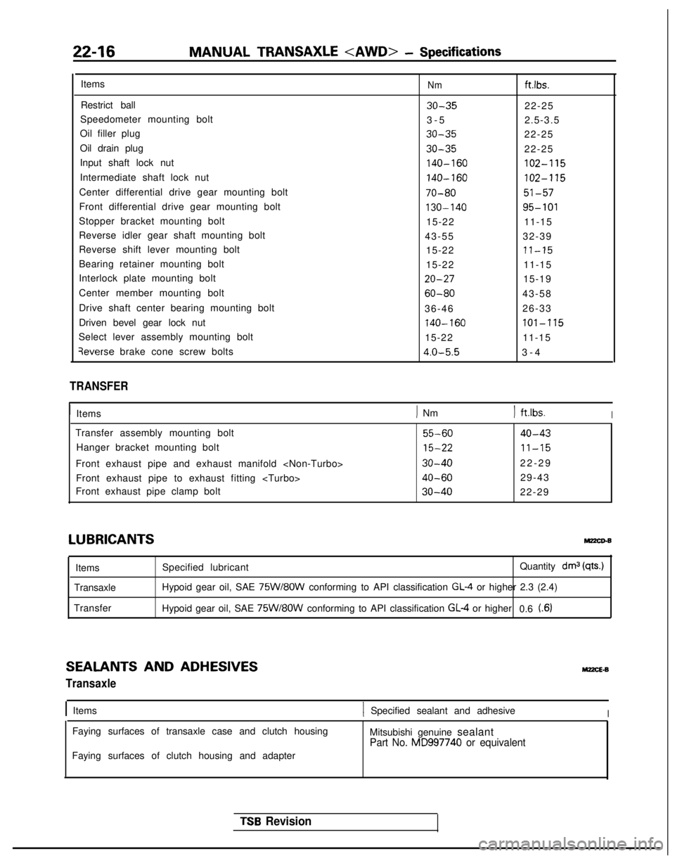
22-16MANUAL TRANSAXLE - Specifications
ItemsNmftlbs.
Restrict ball30-3522-25
Speedometer mounting bolt 3-
5
2.5-3.5
Oil filler plug
30-3522-25
Oil drain plug
30-3522-25
Input shaft lock nut
140-160102-115
Intermediate shaft lock nut140-160102-115
Center differential drive gear mounting bolt70-8051-57
Front differential drive gear mounting bolt130-14095-101
Stopper bracket mounting bolt 15-2211-15
Reverse idler gear shaft mounting bolt 43-5532-39
Reverse shift lever mounting bolt 15-22
71-15
Bearing retainer mounting bolt15-2211-15
Interlock plate mounting bolt
20-2715-19
Center member mounting bolt
60-8043-58
Drive shaft center bearing mounting bolt 36-4626-33
Driven bevel gear lock nut
740-160lOl-‘1’15
Select lever assembly mounting bolt 15-2211-15qeverse
brake cone screw bolts
4.0-5.53-
4
TRANSFER
1
Items
) Nm) ft.lbs.I
Transfer assembly mounting bolt55-6040-43
Hanger bracket mounting bolt15-2211-15
Front exhaust pipe and exhaust manifold 30-4022-2
9
Front exhaust pipe to exhaust fitting
40-6029-43
Front exhaust pipe clamp bolt
30-4022-29
LUBRICANTSMz2co-B
Items
Transaxle
Transfer Specified lubricant
Quantity drnj
(qts.)
Hypoid gear oil, SAE 75W/8OW conforming to API classification GL-4 or higher 2.3 (2.4)
Hypoid gear oil, SAE
75W/8OW conforming to API classification GL-4 or higher 0.6 t.6)
SEALANTS AND ADHESIVES
Transaxle
M22cE.B
IItems1 Specified sealant and adhesiveI
Faying surfaces of transaxle case and clutch housing
Mitsubishi genuine sealant
Part No. MD997740 or equivalent
Faying surfaces of clutch housing and adapter
TSB Revision