1989 MITSUBISHI GALANT clutch
[x] Cancel search: clutchPage 762 of 1273
23-56AUTOMATIC TRANSAXLE - Troubleshooting
Trouble symptom
6. Improper low-
reverse brake
pressure Probable cause
a.O-ring between valve body and
transaxle damaged or missing
b.Looseness of valve body tighten-
ing part
c.Functional malfunction of the
valve body assembly
d.Malfunction of the D-ring 0 of the
low-reverse brake piston or the
O-ring
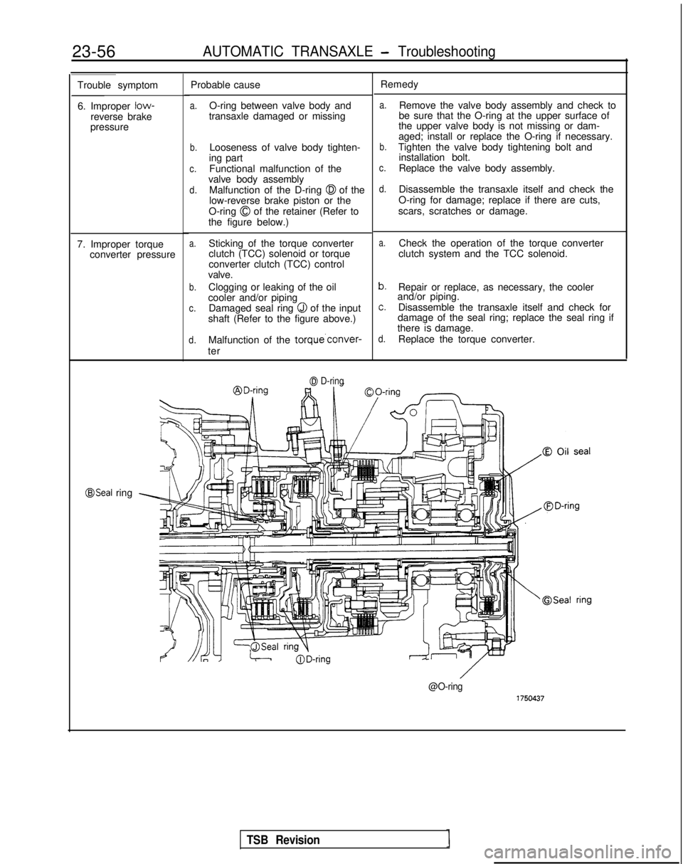
0 of the retainer (Refer to
the figure below.)
a.Sticking of the torque converter
clutch (TCC) solenoid or torque
converter clutch (TCC) control
valve.
b.Clogging or leaking of the oil
cooler and/or piping
c.Damaged seal ring Q of the input
shaft (Refer to the figure above.)
d.Malfunction of the torque’conver-
ter
7. Improper torque
converter pressure
0 D-ring
Remedy
a.Remove the valve body assembly and check to
be sure that the O-ring at the upper surface of
the upper valve body is not missing or dam-
aged; install or replace the O-ring if necessary.
b.Tighten the valve body tightening bolt and installation bolt.
c.Replace the valve body assembly.
d.Disassemble the transaxle itself and check the
O-ring for damage; replace if there are cuts,
scars, scratches or damage.
a.Check the operation of the torque converter
clutch system and the TCC solenoid.
b.Repair or replace, as necessary, the cooler
and/or piping.
c.Disassemble the transaxle itself and check for
damage of the seal ring; replace the seal ring if
there
7s damage.d.Replace the torque converter.
@Seal ring
@O-ring
TSB Revision
Page 763 of 1273
AUTOMATIC TRANSAXLE - Troubleshootinn
23-57
AWD A/T
Problem
Probable cause(s)Remedy
1. All line pressures are a. Clogged oil filter.
low (or high). a. Visually check the oil filter; replace it if it is
b. Improper adjustment of the oil clogged.
NOTEpressure (line pressure) of the
b. Measure line pressure @ (kick-down brake
Line pressures are oil regulator valve.
pressure); readjust the line pressure if there is a
pressures
2 ,, 0, @,
8 c. Malfunction of the valve body
deviation from the standard value, or replace the0, @and 7 In th
e
assembly.
valve body assembly.
standard oil pressure d. Looseness of the valve body
c. Replace the valve body assembly.
table on the preced-
bolts.
d. Tighten the valve body bolts to the specified
ing page. e. Improper discharge pressure of
torque.
the oil pump. e. Check the side clearance of the oil pump gear;
Looseness of each check plug, replace the oil pump assembly if necessary.
or malfunction of the O-ring. f. Check each check plug; replace it if necessary.
2. Inappropriate reduc-
a. Reducing pressure circuit filter a. Disassemble the valve body assembly and check
ing pressure.
(L shaped) is clogged. the filter; replace the filter if
it is clogged.b. Reducing pressure is improperly b. @ Measure the reducing pressure; readjust if
adjusted. there is a diviation from the standard value, or
c. Malfunction of the valve body replace the valve body assembly.
assembly. c. Replace the valve body assembly.
3. Inappropriate kick-
a. Malfunction of the kick-down a. Disassemble the kick-down servo and check the
down brake pressure servo piston’s @ seal ring,
43seal ring, O-ring and D-ring for damage.
(appb).D-ring and/or the sleeve’s 0Replace the seal ring, O-ring or D-ring if they are
O-ring. cut, scarred or scratched.
b. Malfunction of the valve body b. Replace the valve body assembly.
assembly.
1. Inappropriate kick-
down brake release
pressure. a. Malfunction of the kickdownservo piston’s @
seal ring.
b. Malfunction of the valve body assembly. a. Disassemble the kickdown servo and check the
seal ring, for damage. Replace the seal ring if it is cut, scarred or
scratched.
b. Replace the valve body assembly.
j. inappropriate front clutch pressure. a. Malfunction of the kickdowna. Disassemble the kickdown servo and check the
servo piston’s @ seal ring.
seal ring for damage.
b. Malfunction of the valve body Replace the seal ring if it is cut, scarred or
assembly. scratched.
c. Unusual wear or abrasion of the b. Replace the valve body assembly.
front clutch piston and/or the c. Disassemble the transaxle itself and check for
retainer, or malfunction of the
0unusual wear or abrasion of the front clutch
D-ring and/or the @
seal ring. piston and/or retainer inner circumference, or for
damage of the D-ring and/or seal ring.
If unusual wear or abrasion, or damage, is
discovered, replace the piston, retainer, D-ring or
seal ring.
j. Inappropriate rear clutch pressure. a. Malfunction of one or more of
the following parts of the rearclutch: the piston’s
@I D-ring, or
the retainer’s 68 seal ring, or the
input shaft’s @I seal ring or @
O-ring.
b. Malfunction of the valve body assembly. a. Disassemble the rear clutch and check the input
shaft’s O-ring, the retainer’s seal ring, the pis-
ton’s D-ring, etc.; replace any part that is
discovered to be cut, scarred or scratched.
b. Replace the valve body assembly.
Inappropriate end clutch pressure. a. Malfunction of the end clutch’s
($ z;ea/,ring, @I D-ring and/or 0
b. Malfunction of the valve body
assembly. a. Disassemble the end clutch and check the
piston’s oil seal and D-ring, and the retainer’s
seal ring, etc.; replace any part that is cut,
scarred or scratched.
b. Replace the valve body assembly.
1 TSB Revision
Page 764 of 1273
23-58AUTOMATIC TRANSAXLE - Troubleshooting
Problem
8. Inappropriate low-
reverse brake press-
ure.
9. Inappropriate torque converter pressure. Probable cause(s)
a. Damage of the O-ring located between the valve body and the
transaxle.
b. Malfunction of the valve body
assembly.
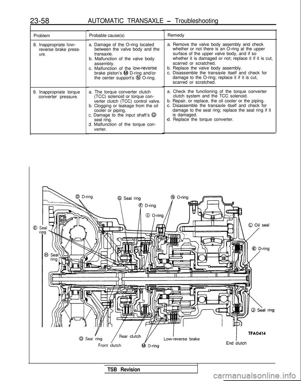
c. Malfunction of the
lo&reversebrake piston’s @I D-ring and/or
the center support’s @I O-ring.
a. The torque converter clutch (TCC) solenoid or torque con-
verter clutch (TCC) control valve.
b. Clogging or leakage from the oil
cooler or piping.
c. Damage to the input shaft’s @
seal ring.
d. Malfunction of the torque con-
verter. Remedy
a. Remove the valve body assembly and check whether or not there is an O-ring at the upper
surface of the upper valve body, and if so
whether it is damaged or not; replace it if it is cut,
scarred or scratched.
b. Replace the valve body assembly.
c. Disassemble the transaxle itself and check for damage to the O-ring; replace it if it is cut,
scarred or scratched.
a. Check the functioning of the torque converter clutch system and the TCC solenoid.
b. Repair, or replace, the oil cooler or the piping.
c. Disassemble the transaxle itself and check for damage to the seal ring; replace the seal ring if itis damaged.
d. Replace the torque converter.
TSB Revision
Page 765 of 1273
AUTOMATIC TRANSAXLE - Troubleshooting23-59
ring
brake
CONVERTER STALL TEST
Stall test consist of determining maximum engine
speed obtained at full throttle in “D” and “R”
positions. This test checks torque converter stator
overrunning clutch operation, and holding ability of
transaxle clutches and low-reserve brake.
Caution
During this test, make sure that no one stand in
front of or behind vehicle.
1. Check transaxle fluid level. Fluid should be at
normal operating temperature [70-80°C (160-
18O”F)j. Engine coolant should also be at normal
operating temperature
[80-90°C (180-19O”F)l.
2. Apply chocks to both rear wheels.
3. Attach engine tachometer.
4. Apply parking and service brakes fully.
5. Start engine.
6. With selector lever in “D” position, depress
accelerator pedal fully to read engine maximum
rpm. Do not hold throttle wide open any longer
than is necessary to obtain maximum engine
rpm reading, and never longer than 5 seconds at
a time. If more than one stall test is required,
operate engine at approximatey 1,000 rpm in
TRANSAXLE CONTROL
neutral for 2 minutes to cool transaxle fluid
between tests.
Stall speed: 1,800-3,200
rpm
7.Place selector lever to “R” position and perform
stall test by the same procedure as in foregoing
item.
Stall Speed Above Specification in “D”
If stall speed is higher than specification, rear clutch
or overrunning clutch of transaxle is slipping. In this
case, perform hydraulic test to locate cause of
slippage.
Stall Speed Above Specification in “I?”
If stall speed is higher than specification, front
clutch of transaxle or low-reverse brake is slipping. In this case, perform hydraulic test to locate cause
of slippage.
Stall Speed Below Specification in “D” and “R”
If stall speed is lower than specification, insufficient
engine output or faulty torque converter is sus-
pected. Check for engine misfiring, ignition timing,
valve clearance etc. If these are good, torque
converter is faulty. Svmotom
Probable cause
Remedy
Selector lever operation is Incorrect adjustment of sleeve
1 Adjust
stiff
Starter motor does not oper-
Incorrect adjustment of control cable
Excessive wear of detent plate
Worn contact surfaces of pushbutton and sleeve
Malfunction in park/neutral position switch Replace
Replace
ate with the selector lever in
the
“N” or “P” position Malfunction of starter relayI
Incorrect adjustment of control cable
AdjustI
W
ill not shift to 4-speed
( Malfunction of OD switch) ReplaceI
TSB Revision
Page 788 of 1273
23-82AUTOMATIC TRANSAXLE - Service Adjustment Procedures
HOTTFA0715
AWD
LT FA0700J
SERVICE ADJUSTMENT PROCEDUR&g
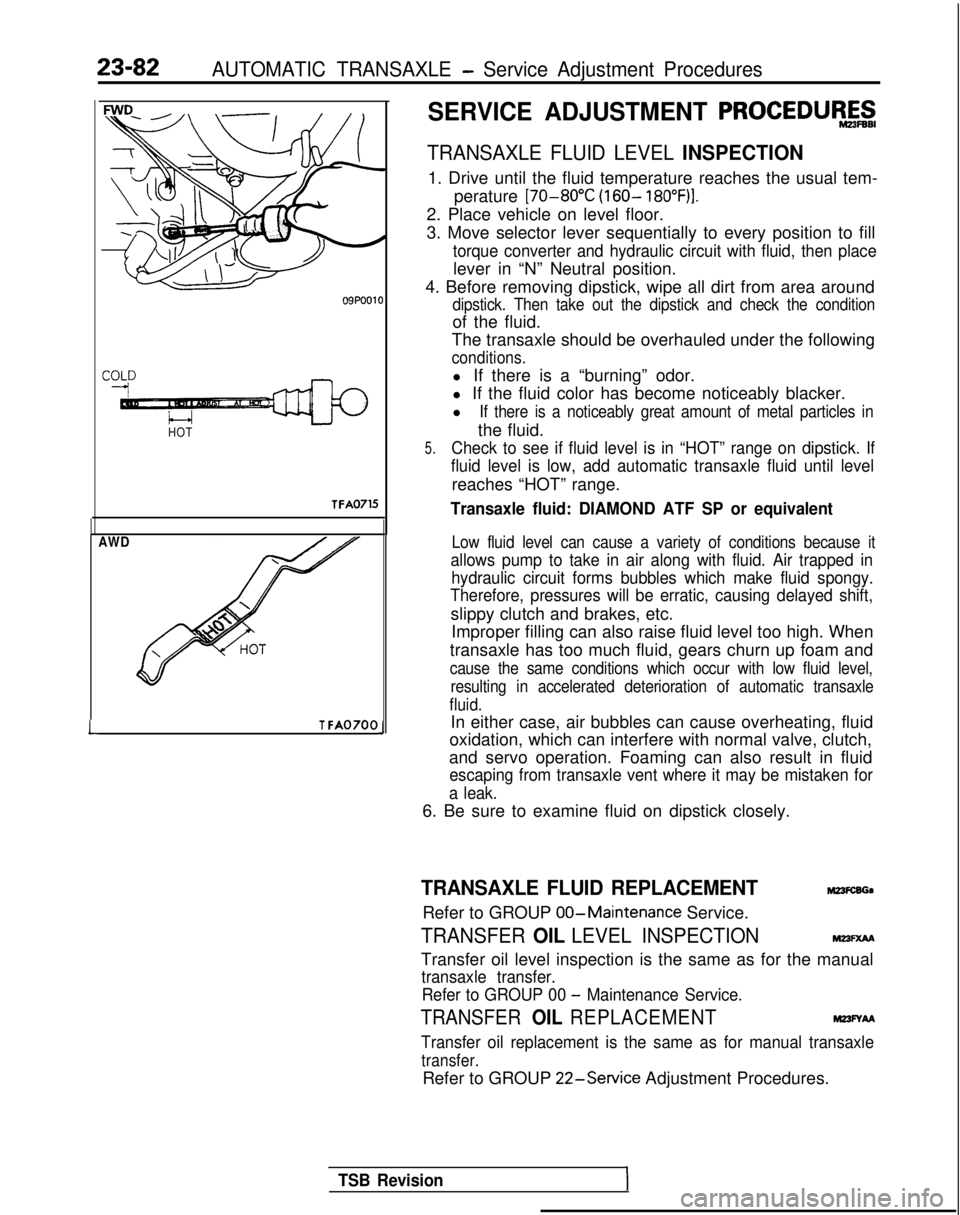
TRANSAXLE FLUID LEVEL INSPECTION
1. Drive until the fluid temperature reaches the usual tem-
perature [70-80°C
(160- 18O”F)I.
2. Place vehicle on level floor.
3. Move selector lever sequentially to every position to fill
torque converter and hydraulic circuit with fluid, then place
lever in “N” Neutral position.
4. Before removing dipstick, wipe all dirt from area around
dipstick. Then take out the dipstick and check the condition
of the fluid.
The transaxle should be overhauled under the following
conditions.
l If there is a “burning” odor.
l If the fluid color has become noticeably blacker.
l
If there is a noticeably great amount of metal particles in
the fluid.
5.Check to see if fluid level is in “HOT” range on dipstick. If
fluid level is low, add automatic transaxle fluid until level
reaches “HOT” range.
Transaxle fluid: DIAMOND ATF SP or equivalent
Low fluid level can cause a variety of conditions because it
allows pump to take in air along with fluid. Air trapped in hydraulic circuit forms bubbles which make fluid spongy.
Therefore, pressures will be erratic, causing delayed shift,
slippy clutch and brakes, etc.
Improper filling can also raise fluid level too high. When
transaxle has too much fluid, gears churn up foam and
cause the same conditions which occur with low fluid level, resulting in accelerated deterioration of automatic transaxle
fluid.
In either case, air bubbles can cause overheating, fluid
oxidation, which can interfere with normal valve, clutch,
and servo operation. Foaming can also result in fluid
escaping from transaxle vent where it may be mistaken for
a leak.
6. Be sure to examine fluid on dipstick closely.
TRANSAXLE FLUID REPLACEMENTM23FcsGa
Refer to GROUP 00-Maintenance
Service.
TRANSFER OIL LEVEL INSPECTIONMm=xM
Transfer oil level inspection is the same as for the manual
transaxle transfer.
Refer to GROUP 00
- Maintenance Service.
TRANSFER OIL REPLACEMENTM23FYAA
Transfer oil replacement is the same as for manual transaxle
transfer.
Refer to GROUP 22-Service
Adjustment Procedures.
TSB Revision
Page 1131 of 1273
35-10SERVICE BRAKES - Specifications
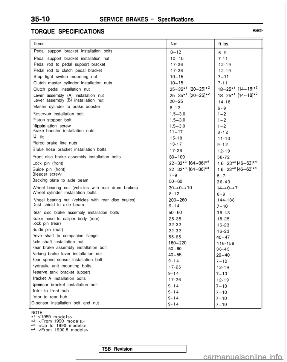
TORQUE SPECIFICATIONS
Items
Pedal support bracket installation bolts
Pedal support bracket installation nut
Pedal rod to pedal support bracket
Pedal rod to clutch pedal bracket
Stop light switch mounting nut
Clutch master cylinder installation nuts
Clutch pedal installation nut
Lever assembly (A) installation nut
-ever assembly (B) installation nut Vlaster
cylinder to brake booster qeservoir
installation bolt
‘iston stopper bolt Vipple installation screw
3rake booster installation nuts
q itting
Ilared brake line nuts
3rake hose bracket installation bolts
+ont disc brake assembly installation bolts
-ock
pin (front) 3uide
pin (front)
31eeder screw
3acking plate to axle beam
JVheel bearing nut (vehicles with rear drum brakes)
JVheel cylinder installation bolts Yheel
bearing nut (vehicles with rear disc brakes)
just shield to axle beam
Iear disc brake assembly installation bolts
srake hose to caliper body (rear)
.ock pin (rear)
&ride pin (rear)
Irive shaft to companion flange
\xle shaft installation nut
Ieserve tank bracket (upper)
bracket A installation bolts ;peed sensor bracket installation bolt
totor to front hub
‘otor to rear hub
G-sensor installation bolt and nut
NOTE*I:
~2:
Nmft.lbs.
8-126-
9
IO-157-11
17-26 12-19
17-26 12-19
IO-157-l 1
IO-157-11
,25-35”’ [20-251*218-25”’ [14-181*2
25-35*’ [20-251*218-25*’
[14-181*2
20-2514-18
8-1
2
6-9
1.5-3.0l-2
1.5-3.0l-2
1.5-3.0l-2
11-178-1
2
15-18 11-13
13-17 9-12
17-26 12-19
80-10058-72
22-32*3 [64-86]*41 6-23*3 [46-621*4
22-32*3 [64-86]*41 6-23*3 [46-62]*4
7-
9
5-7
50-6036-4
3
20~0~1014-047
8-1
2
6-9 ZOO-260
144-188
9-14
7-10
50-6036-4
3
25-35 18-25
22-32 16-23
22-32 16-23
55-65
40-47
160-220116-159
50-6036-4
3
40-5529-40
9-1
4
7-10
17-26
12-19
9-1
4
7-10
17-26
12-19
9-1
4
7-10
9-1
4
7-10
9-1
4
7-10
9-1
4
7-10
TSB Revision
Page 1197 of 1273
35-76SERVICE BRAKES - Brake Pedal
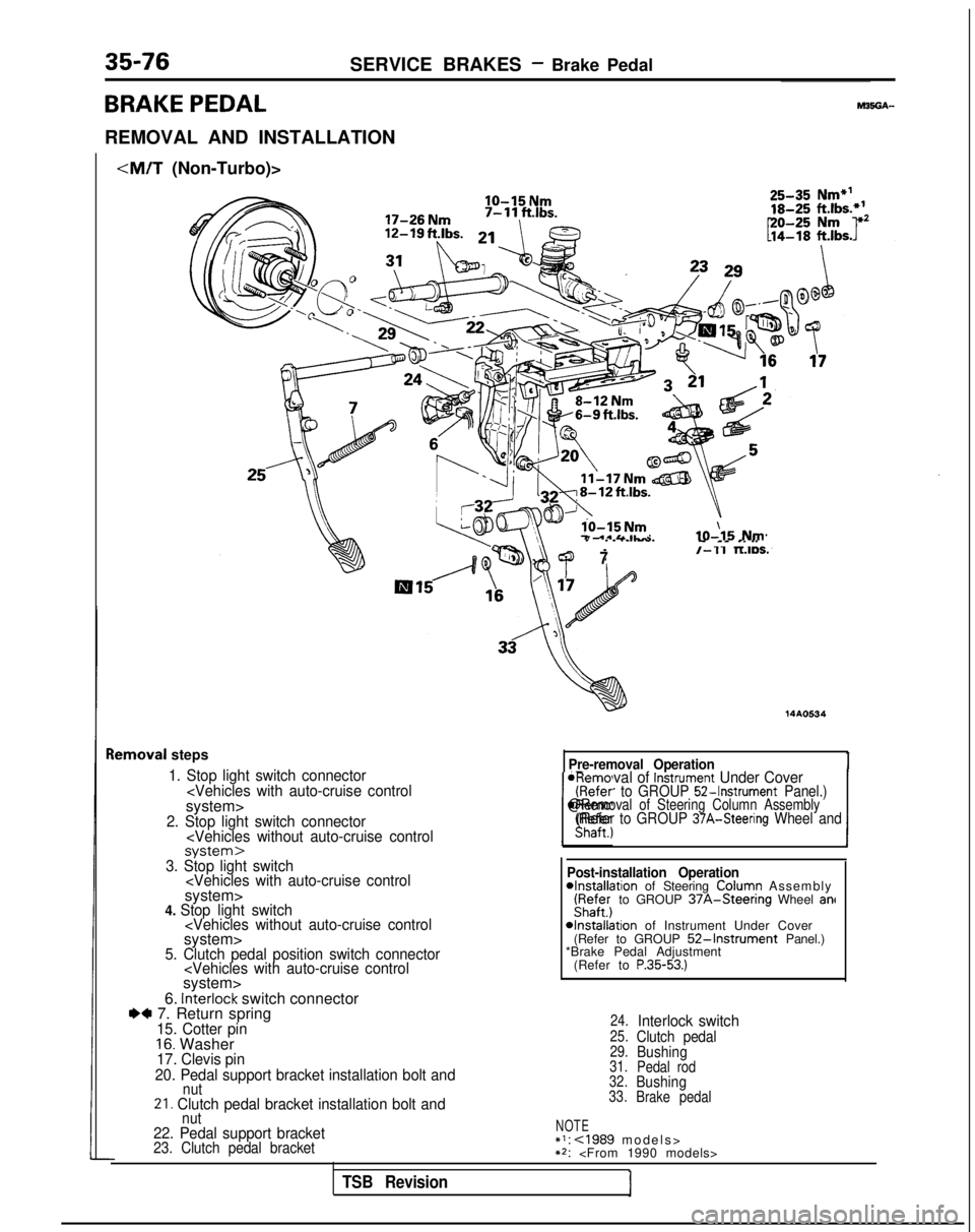
BRAKE PEDAL
REMOVAL AND INSTALLATION
IO-15 Nm
lo-15 Nm7 .*&&IL-IO-\15 Nm
lemoval
steps
1. Stop light switch connector
7/-11 TLIDS.
14AO534
Pre-removal Operation
*Removal of Instrument Under Cover(Refer to GROUP 52-Instrument Panel.)
IShaft., 1
@Removal of Steering Column Assembly(Refer to GROUP 37A-Steering Wheel and
-I---.3. Stop light switch
6. interlock switch connectorI)* 7. Return spring15. Cotter pin16. Washer17. Clevis pin
20. Pedal support bracket installation bolt and
nut21. Clutch pedal bracket installation bolt and Post-installation Operation
4nstallation of Steering ColuFn Assembl
y
iyafe;j to GROUP 37A-Steenng Wheel ant
4nstallation of Instrument Under Cover
(Refer to GROUP 52-Instrument Panel.)
*Brake Pedal Adjustment
(Refer to
P.35-53.)
24.Interlock switch25.Clutch pedal29.Bushing31. Pedal rod
32.Bushing33. Brake pedal
nut22. Pedal support bracketNOTE*I: cl989 models
>
23. Clutch pedal bracket**:
TSB Revision
Page 1198 of 1273
SERVICE BRAKES - Brake Pedal35-77
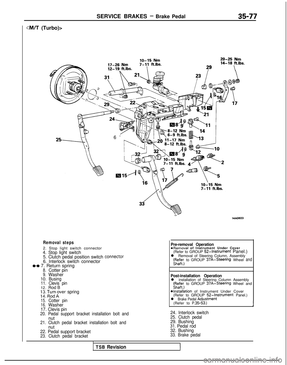
:M/T (Turbo)>
lo-15 Nm20-25 Nm
17-26 Nm7-11
ftlbs. 14-18
ft.lbs.
12-19. ft.lbs.I?9\ a-
6’
Removal steps
2. Stop light switch connector4. Stop light switch
5. Clutch pedal position switch connector
6. Interlock switch connectorI)+ 7. Return spring8.Cotter pin9.Washer10.Busing11.Clevis pin12.RodB; 2: ‘,l%;rer spring
15.Cotter pin16.Washer
17. Clevis pin
20. Pedal support bracket installation bolt andnut21. Clutch pedal bracket installation bolt andnut
22. Pedal support bracket
23. Clutch pedal bracket
- 14AO623
Pre-removal Operation
*Removal
of Instrument Under Cover
(Refer to GROUP
52-Instrument Panel.)
l Removal of Steering Column, Assembly r;affer)
to GROUP
37A-Steenng Wheeland
I
Post-installation Operationl installation of Steering Column Assembly(Fyaffer) to GROUP 37A-Steenng Wheel and
*Installation of Instrument Under Cover
(Refer to GROUP 52-Instrument Panel.)l Brake Pedal Adiustment
(Refer to P.35-53.)1
24. Interlock switch25. Clutch pedal29. Bushing31. Pedal rod
32. Bushing
33. Brake pedal
TSB RevisionI