1989 MITSUBISHI GALANT ECO mode
[x] Cancel search: ECO modePage 3 of 1273

00-l
GENERAL
CONTENTS
GENERAL DATA AND SPECIFICATIONS.....23
HOWTOUSETHISMANUAL......................
3
Definition of Terms ......................................3
ExplanationofCircuitDiagrams..................7
Explanation of
ManualContents .................4
Explanation of the Troubleshooting
Guide .............................................................
6
Model
Indications .........................................3
Scope of Maintenance, Repair and
Servicing Explanations
..................................
3
Troubleshooting .............................................3
LUBRICATIONANDMAINTENANCE............
34
MAINTENANCE SERVICE............................... 39
AirCleanerElement
.....................................39
Automatic
Transaxle
.....................................43
Ball Joint and Steering Linkage Seals ........45
Brake Hoses................................................. 45
Disc Brake Pads ........................................... 44
Drive Belt (For Water Pump and
Generator) .......................................................
41
Drive
Shaft Boots .........................................45
Engine Coolant
............................................. 44
Engine Oil .....................................................
41
Engine Oil Filter ...........................................41
Exhaust System
............................................ 45
FuelHoses
...................................................39
Fuel System
.................................................39
Manual Transaxle ..........................................42
RearAxle......................................................45
Rear Drum Brake Linings and
RearWheel Cylinders
..................................44
Spark
Plugs...................................................40
Timing Belt...................................................40
MASTER
TROUBLESHOOTING.....................28
PRECAUTIONS
BEFORESERVICE................15
RECOMMENDED LUBRICANTS AND
LUBRICANT CAPACITIESTABLE..................35
SCHEDULED
MAINTENANCETABLE ...........38
SPECIAL HANDLING INSTRUCTIONS
FOR AWD MODELS
.......................................20
TABLE OF MAIN SEALANTS
AND
ADHESIVES ............................................46
TIGHTENING TORQUE
................................... 27
TOWING
ANDHOISTING ..............................17
VEHICLE
IDENTIFICATION .............................8
Chassis Number ...........................................
11
EngineModel
Stamping
...............................12
Theft Protection ............................................12
Vehicle Identification Code Chart Plate.......
8
Vehicle Identification Number List
..............8
Vehicle Identification Number Location .......
8
Vehicle Information
CodePlate...................1 1
Vehicle SafetyCertificationLabel................12
Page 38 of 1273
00-36
GENERAL -Recommended Lubricants and Lubricant Capacities Table
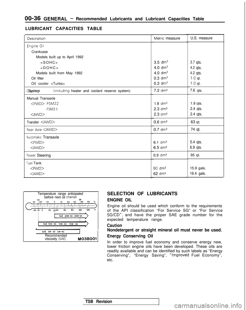
LUBRICANT CAPACITIES TABLE
Descrrptron
Engrne 011
Crankcase
Models built up to April 1992
Models built from May 1992
Oil filter
Oil cooler
(rncludrng heater and coolant reserve system)
Manual Transaxle
F5M3
1
Transfer
qear Axle
4utomatrc Transaxle
‘ower Steering %el
Tank
Metric measure
3.5 dm3
4.0 dm3
4.0 dm3
0.3 dm3
0.3 dm3
7.2 dm3
1.8 dm31.9 qts.
2.3
dm32.4 qts.
2.3 dm32.4 qts.
3.6 dm363 qt.
3.7
dm374 qt.
6.1 dm3
6.5 dms
3.9 dm3 60
dm3
62 dm3
U.S. measure
3.7qts.
4.2qts.
4.2qts.
1 I2qt.
1 I2qt.
7.6qts.
5.4 qts.
6.9 qts.
95 qt.
15.9 gals.
16.4 gals.
Temperature range anticipated before next oil chanae
SAE SW-30 SW-40IRecommendedviscosity (SAE) M03BOOl
SELECTION OF LUBRICANTS
ENGINE OIL
Engine oil should be used which conform to the requirements
of the API classification “For Service SG” or “For Service
SGKD”, and have the proper SAE grade number for the
expected temperature range.
Caution
Nondetergent or straight mineral oil must never be used.
Energy Conserving Oil
In order to improve fuel economy and conserve energy new,
lower friction engine oils have been developed. These oils are readily available and can be identified by such labels as “Energy
Conserving”, “Energy Saving”,
“Improved Fuel Economy”,
etc.
TSB Revision
Page 43 of 1273
GENERAL - Maintenance Service00-41
-1
6COOO9
L!6COO39
OlR0344
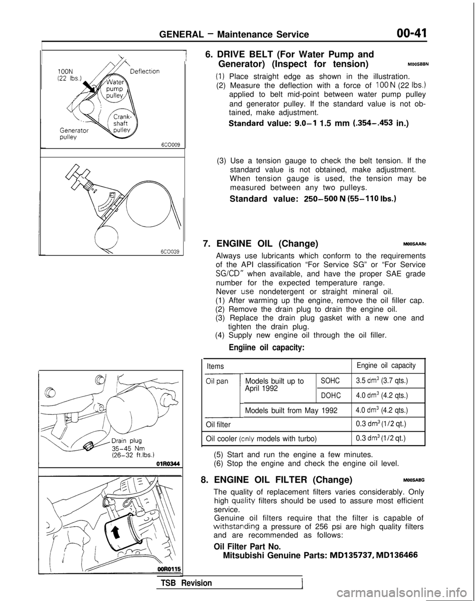
6. DRIVE BELT (For Water Pump and
Generator) (Inspect for tension)
MOOSBBN
(1) Place straight edge as shown in the illustration.
(2) Measure the deflection with a force of
100 N (22 Ibs.)
applied to belt mid-point between water pump pulley
and generator pulley. If the standard value is not ob-
tained, make adjustment.
Standard value: 9.0-l 1.5 mm (.354-.453
in.)
(3) Use a tension gauge to check the belt tension. If the standard value is not obtained, make adjustment.
When tension gauge is used, the tension may be
measured between any two pulleys.
Standard value:
250-500 N (55-110
Ibs.)
7. ENGINE OIL (Change)MOOSAABc
Always use lubricants which conform to the requirements
of the API classification “For Service SG” or “For Service SG/CD”
when available, and have the proper SAE grade
number for the expected temperature range.
Never
Lose nondetergent or straight mineral oil.
(1) After warming up the engine, remove the oil filler cap.
(2) Remove the drain plug to drain the engine oil. (3) Replace the drain plug gasket with a new one and
tighten the drain plug.
(4) Supply new engine oil through the oil filler.
Engiine oil capacity:
Items Engine oil capacity
Oil pan
1
Models built up toSOHC3.5 dm3 (3.7 qts.)
April 1992DOHC4.0 dm3 (4.2 qts.)
Models built from May 19924.0 dm3 (4.2 qts.)
Oil filter 0.3 dm3 (l/2 qt.)
Oil cooler
(clnly models with turbo) 0.3 dm3 (I/2 qt.)
(5) Start and run the engine a few minutes.
(6) Stop the engine and check the engine oil level.
8. ENGINE OIL FILTER (Change)
MOOSABG
The quality of replacement filters varies considerably. Only high
quatlity filters should be used to assure most efficient
service. Genuine oil filters require that the filter is capable of
withstarlding a pressure of 256 psi are high quality filters
and are recommended as follows:
Oil Filter Part No.
Mitsubishi Genuine Parts: MD135737,
MD136466
TSB Revision
Page 159 of 1273
FUEL SYSTEM
\ I\-\\\\\\6FUO807
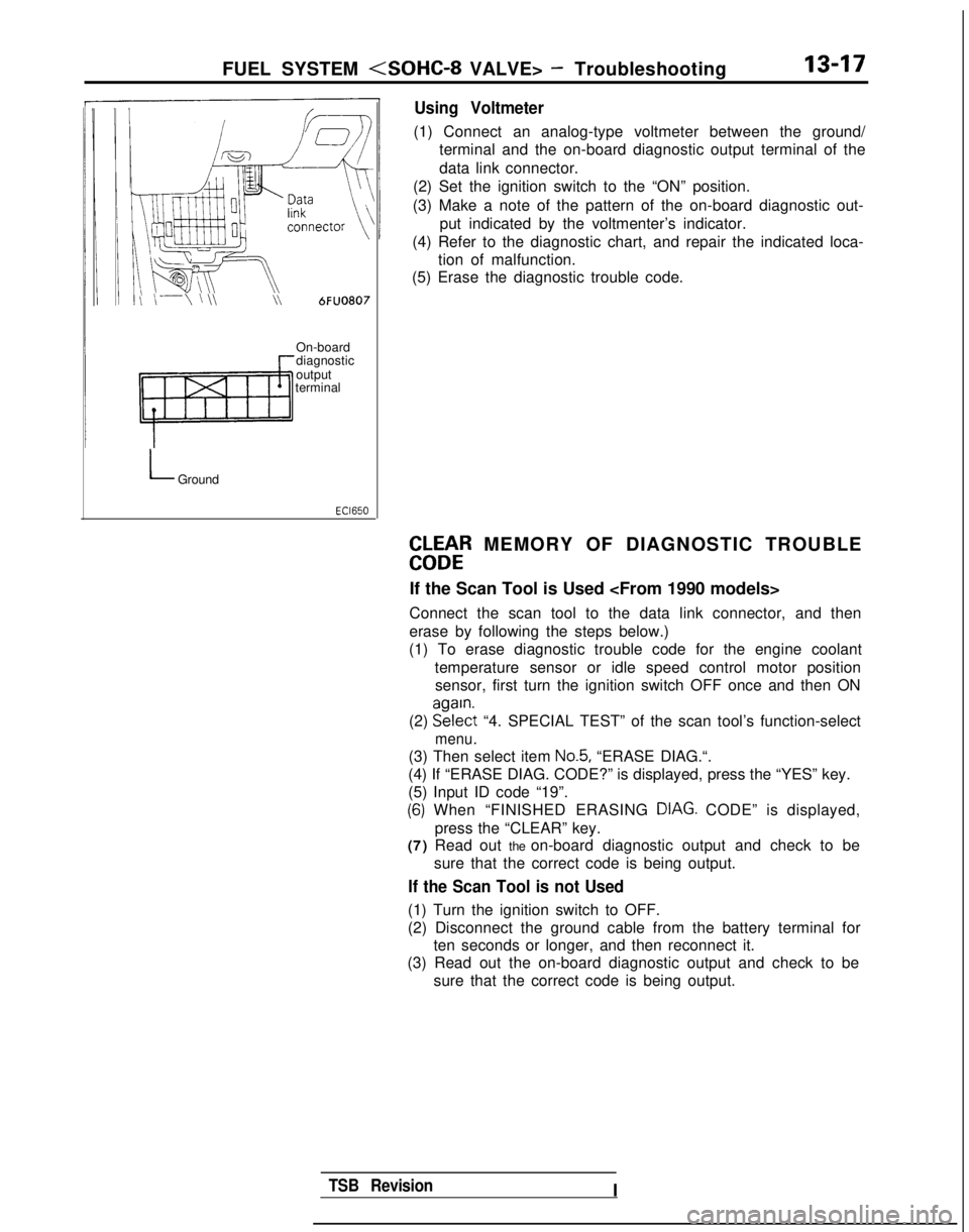
Using Voltmeter
(1) Connect an analog-type voltmeter between the ground/
terminal and the on-board diagnostic output terminal of the
data link connector.
(2) Set the ignition switch to the “ON” position.
(3) Make a note of the pattern of the on-board diagnostic out- put indicated by the voltmenter’s indicator.
(4) Refer to the diagnostic chart, and repair the indicated loca- tion of malfunction.
(5) Erase the diagnostic trouble code.
On-board
diagnostic
output
terminal
LGround
EbLbtR MEMORY OF DIAGNOSTIC TROUBLE
If the Scan Tool is Used
Connect the scan tool to the data link connector, and then
erase by following the steps below.)
(1) To erase diagnostic trouble code for the engine coolant
temperature sensor or idle speed control motor positionsensor, first turn the ignition switch OFF once and then ON
(2) EE?$t
“4. SPECIAL TEST” of the scan tool’s function-select
menu.
(3) Then select item No.5, “ERASE DIAG.“.
(4) If “ERASE DIAG. CODE?” is displayed, press the “YES” k\
ey.
(5) Input ID code “19”.
(6) When “FINISHED ERASING DIAG. CODE” is displayed,> Ipress the “CLEAR” key.
(7) Read out the on-board diagnostic output and check to be
sure that the correct code is being output.
If the Scan Tool is not Used
(1) Turn the ignition switch to OFF.
(2) Disconnect the ground cable from the battery terminal forten seconds or longer, and then reconnect it.
(3) Read out the on-board diagnostic output and check to be
sure that the correct code is being output.
TSB RevisionI
Page 176 of 1273
13-34 FUEL SYSTEM
(5) Switch ON the ignition switch (but do not start the engine)and leave as if for 15 seconds or longer.
NOTE
When the ignition switch is switched ON, the idle speed
control plunger extends to the fast-idle opening degree,
and, after 15 seconds have passed, contracts to the initialposition and stops there.
Initial position: the suitable idling position at which the idle speed control motor position sensor output
voltage is
0.9V.
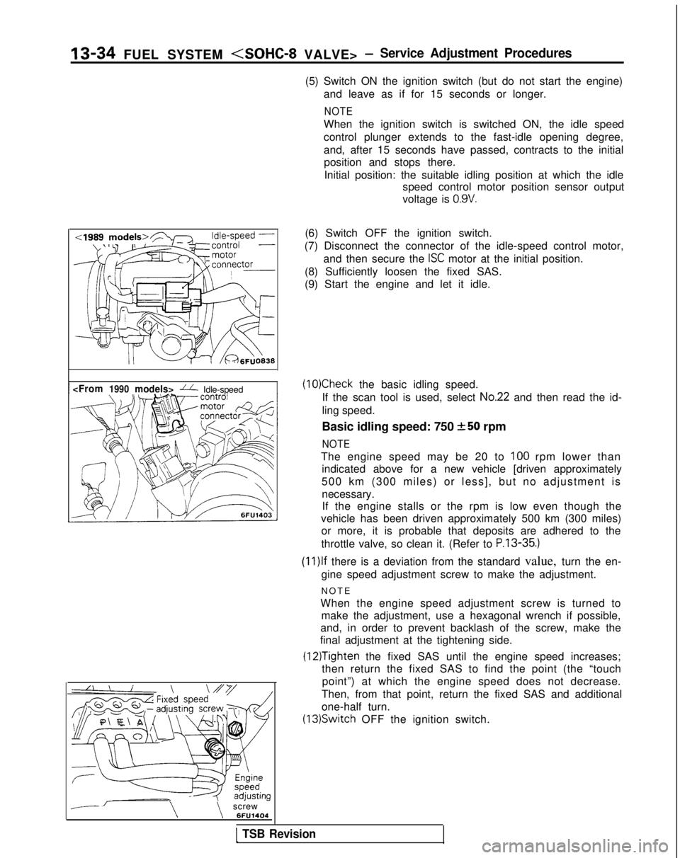
--\\screw 6FU1404(6) Switch OFF the ignition switch.
(7) Disconnect the connector of the idle-speed control motor, and then secure the
ISC motor at the initial position.
(8) Sufficiently loosen the fixed SAS.
(9) Start the engine and let it idle.
(10)Check the basic idling speed.
If the scan tool is used, select
No.22 and then read the id-
ling speed.
Basic idling speed: 750
+-50 rpm
NOTE
The engine speed may be 20 to 100 rpm lower than
indicated above for a new vehicle [driven approximately
500 km (300 miles) or less], but no adjustment is necessary.If the engine stalls or the rpm is low even though the
vehicle has been driven approximately 500 km (300 miles) or more, it is probable that deposits are adhered to the
throttle valve, so clean it. (Refer to
P.13-35.)
(1l)lf there is a deviation from the standard value, turn the en-
gine speed adjustment screw to make the adjustment.
NOT
E
When the engine speed adjustment screw is turned to make the adjustment, use a hexagonal wrench if possible,
and, in order to prevent backlash of the screw, make the
final adjustment at the tightening side.
(12)Tighten the fixed SAS until the engine speed increases;
then return the fixed SAS to find the point (the “touch
point”) at which the engine speed does not decrease.
Then, from that point, return the fixed SAS and additional
one-half turn. (13)Switch
OFF the ignition switch.
1 TSB Revision
Page 177 of 1273
FUEL SYSTEM
(14)Adjust the play of the accelerator cable. (Refer to P.13-
329.)
(15)Connect the idle-speed control motor’s connector.
(16)Adjust the throttle-position sensor.
(17)Start the engine again and let it run at idle speed for about
ten minutes; check to be sure that the idling condition is
normal.
THROTTLE BODY (THROTTLE VALVE AREA)
CLEANING
MllFlCK
(1)Start the engine and warm it up until the temperature of the
engine coolant reaches
80°C (176°F) or higher; then stop
the engine.
(2) Disconnect the air intake hose at the throttle body side.
(3) Spray cleaning liquid (from the intake port of the throttle body) onto the valve, and then leave as is for about fiveminutes.
(4) Start the engine and race it a few times; then let it run at idle speed for about one minute.
NOTE
If the engine idling speed is unstable (or the engine stalls),
let the engine run with the throttle valve slightly open.
(5) If deposits are not removed from the throttle valve, repeat steps (3) and (4).
(6) Connect the air intake hose.
(7) Using the scan tool, erase the diagnostic trouble code, or disconnect the battery’s ground cable for ten seconds orlonger and then reconnect it.
(8) Adjust the basic idle speed (engine speed adjusting screw). (Refer to
P.13-33.)
(9) Adjust the throttle position sensor.
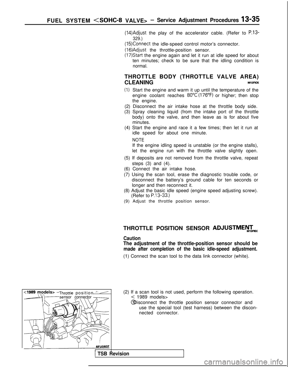
(2) If a scan tool is not used, perform the following operation.
< 1989 models> @ Disconnect the throttle position sensor connector and
use the special tool (test harness) between the discon-
nected connector.
r1 TSB Revision
THROTTLE POSITION SENSOR ADJUSTMEiW&
Caution
The adjustment of the throttle-position sensor should be
made after completion of the basic idle-speed adjustment.
(1) Connect the scan tool to the data link connector (white).
,
Page 178 of 1273
13-36 FUEL SYSTEM
:I989 models>
M
D9684783FUO179
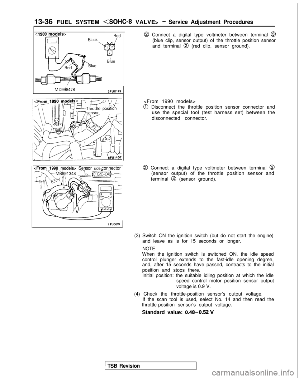
@ Connect a digital type voltmeter between terminal @
(blue clip, sensor output) of the throttle position sensor
and terminal
@I (red clip, sensor ground).
@I Disconnect the throttle position sensor connector and use the special tool (test harness set) between the
disconnected connector.
@ Connect a digital type voltmeter between terminal @
(sensor output) of the throttle position sensor and
terminal
@I (sensor ground).
1 FU0619
(3) Switch ON the ignition switch (but do not start the engine) and leave as is for 15 seconds or longer.
NOTE
When the ignition switch is switched ON, the idle speedcontrol plunger extends to the fast-idle opening degree,
and, after 15 seconds have passed, contracts to the initial
position and stops there.Initial position: the suitable idling position at which the idle speed control motor position sensor output
voltage is 0.9 V.
(4) Check the throttle-position sensor’s output voltage. If the scan tool is used, select No. 14 and then read the
throttle-position sensor’s output voltage.
Standard value: 0.48-0.52
V
1 TSB Revision
Page 183 of 1273
FUEL SYSTEM
Ciaarette
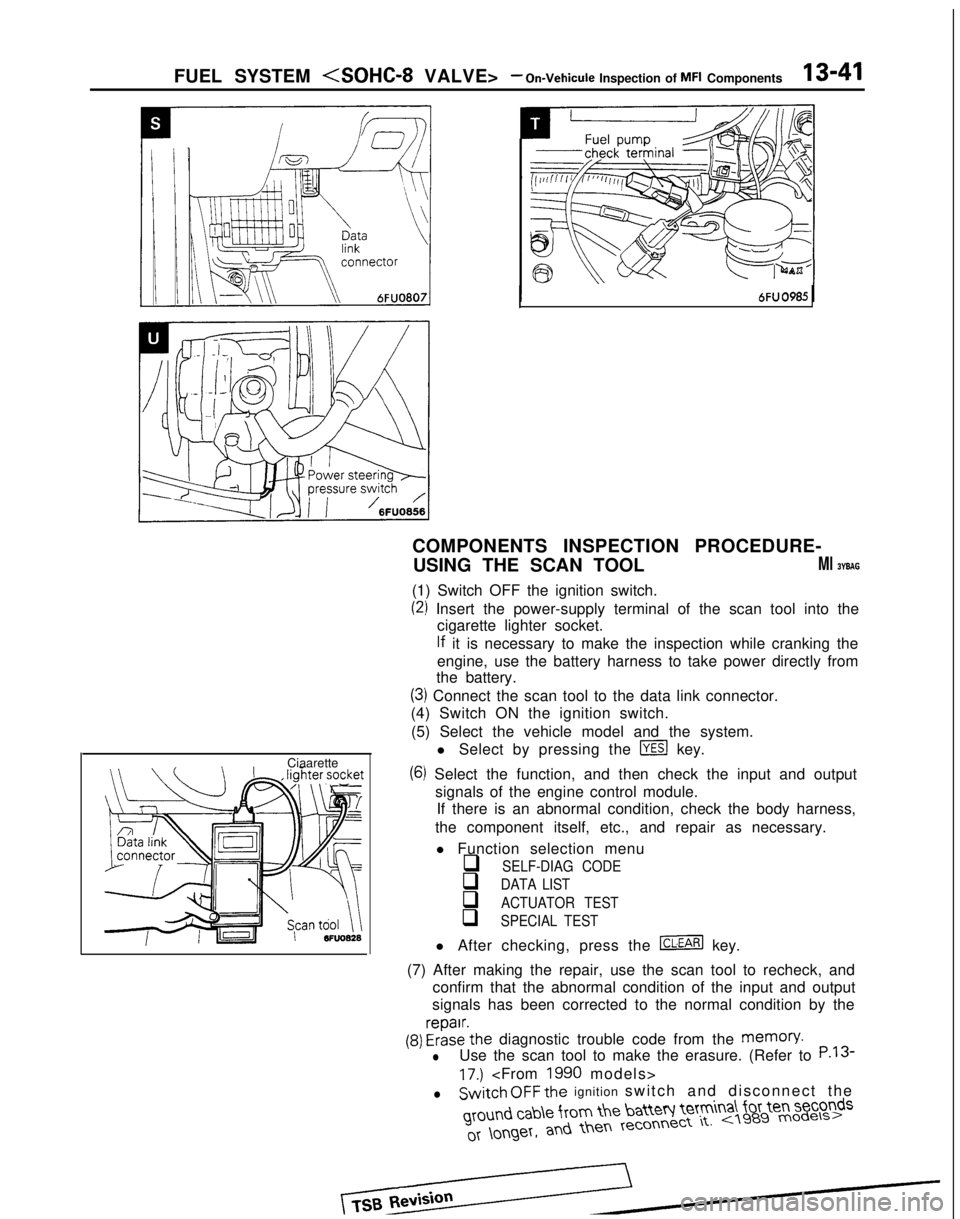
COMPONENTS INSPECTION PROCEDURE-
USING THE SCAN TOOL
Ml BYBAG
(1) Switch OFF the ignition switch.
(2) Insert the power-supply terminal of the scan tool into the cigarette lighter socket.
lf it is necessary to make the inspection while cranking the
engine, use the battery harness to take power directly from
the battery.
(3) Connect the scan tool to the data link connector.
(4) Switch ON the ignition switch.
(5) Select the vehicle model and the system. l Select by pressing the
m key.
(6) Select the function, and then check the input and outputsignals of the engine control module.If there is an abnormal condition, check the body harness,
the component itself, etc., and repair as necessary.
l Function selection menu
q SELF-DIAG CODE
q DATA LIST
q ACTUATOR TEST
q SPECIAL TEST
l After checking, press the m key.
(7) After making the repair, use the scan tool to recheck, and confirm that the abnormal condition of the input and output
signals has been corrected to the normal condition by the
(9) FrizE’the diagnostic trouble code from the memory.
lUse the scan tool to make the erasure. (Refer to P.13
17.)
lSwitch OFF the ignition switch and disconnect the ground
cab\e from the batteq Ie’tm
a\ for ten seconds