Page 885 of 1273
REAR AXLE - Drive Shaft27-25
t
Snap
inner race
1180116
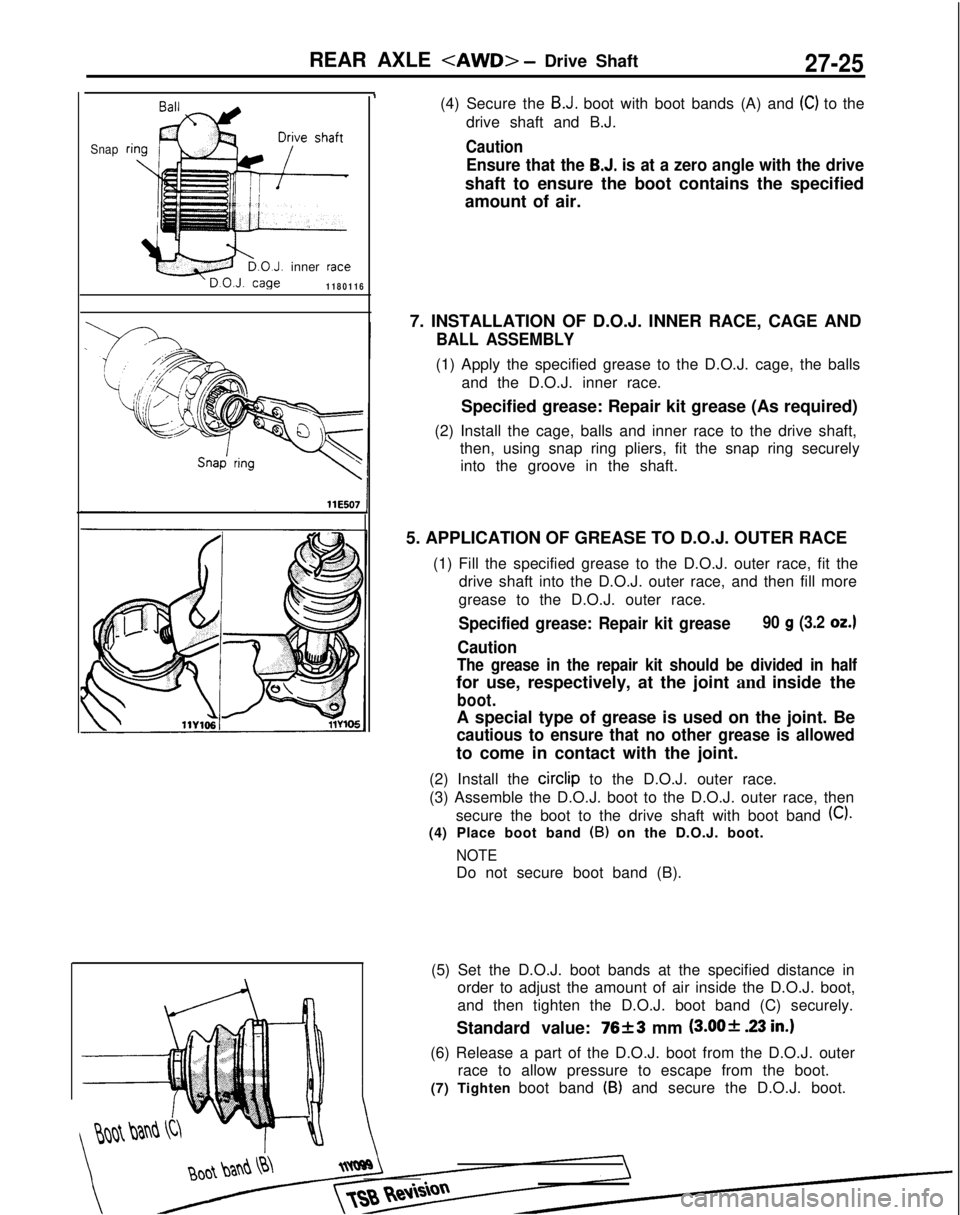
(4) Secure the B.J. boot with boot bands (A) and (C) to the
drive shaft and B.J.
Caution
Ensure that the B.J. is at a zero angle with the drive
shaft to ensure the boot contains the specified
amount of air.
7. INSTALLATION OF D.O.J. INNER RACE, CAGE AND
BALL ASSEMBLY
(1) Apply the specified grease to the D.O.J. cage, the balls and the D.O.J. inner race.
Specified grease: Repair kit grease (As required)
(2) Install the cage, balls and inner race to the drive shaft, then, using snap ring pliers, fit the snap ring securelyinto the groove in the shaft.
5. APPLICATION OF GREASE TO D.O.J. OUTER RACE (1) Fill the specified grease to the D.O.J. outer race, fit thedrive shaft into the D.O.J. outer race, and then fill more
grease to the D.O.J. outer race.
Specified grease: Repair kit grease90 g (3.2 OZ.)
Caution
The grease in the repair kit should be divided in half
for use, respectively, at the joint and inside the
boot.
A special type of grease is used on the joint. Be
cautious to ensure that no other grease is allowed
to come in contact with the joint.
(2) Install the circlip
to the D.O.J. outer race.
(3) Assemble the D.O.J. boot to the D.O.J. outer race, then secure the boot to the drive shaft with boot band
(C).
(4) Place boot band (B) on the D.O.J. boot.
NOTE
Do not secure boot band (B).
(5) Set the D.O.J. boot bands at the specified distance in order to adjust the amount of air inside the D.O.J. boot,
and then tighten the D.O.J. boot band (C) securely.
Standard value:
76f3 mm @JO+ 23 in.)
(6) Release a part of the D.O.J. boot from the D.O.J. outer race to allow pressure to escape from the boot.
(7) Tighten boot band
(B) and secure the D.O.J. boot.
Page 942 of 1273
ACTIVE-ELECTRONIC CONTROL SUSPENSION - Specifications33B-3
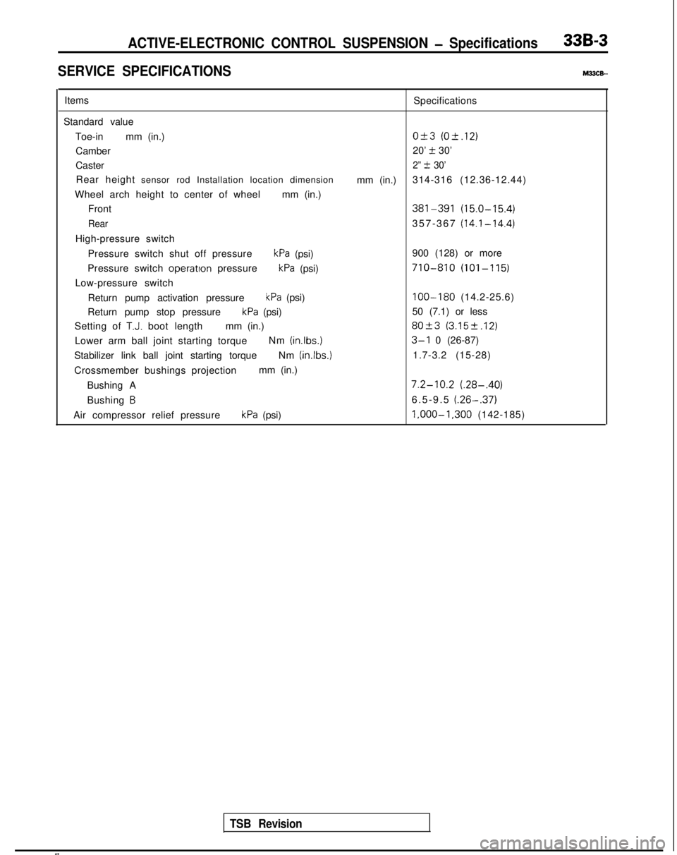
SERVICE SPECIFICATIONSM33cE-
ItemsSpecifications
Standard value Toe-in mm (in.)
O&3 (O-t.12)
Camber 20’ t 30’
Caster
2” t 30’
Rear height sensor rod Installation location dimension
mm (in.)314-316 (12.36-12.44)
Wheel arch height to center of wheel mm (in.)
Front
381-391 (15.0-15.4)
Rear357-367 (14.1-14.4)
High-pressure switch
Pressure switch shut off pressure
kPa (psi) 900 (128) or more
Pressure switch operatton
pressure
kPa (psi)710-810 (101-115)
Low-pressure switch
Return pump activation pressure
kPa (psi)100-180 (14.2-25.6)
Return pump stop pressure
kPa (psi) 50 (7.1) or less
Setting of
T.J. boot length mm (in.)80+3 (3.152.12)
Lower arm ball joint starting torque Nm (inlbs.)3-l 0 (26-87)
Stabilizer link ball joint starting torque Nm (in.lbs.)
1.7-3.2 (15-28)
Crossmember bushings projection mm (in.)
Bushing A
7.2-10.2 (.28-.40)
Bushing B6.5-9.5 (.26-.37)
Air compressor relief pressurekPa (psi) l,OOO-1,300
(142-185)
TSB Revision
Page 1132 of 1273
SERVICE BRAKES - Specifications/Special Tools35-l 1
LUBRICANTS
Items
Brake fluid
Brake piston seal
Brake piston boot inner surfaces
Brake lock pin boot inner surfaces
Guide pin boot inner surfaces
Lock pin sleeve
Guide pin and caliper support contact surface
Lock pin and caliper support contact surface
Rear drum brake wheel cylinder ends
Spindle lever, lever boot, connecting link, O-ring and
auto adjuster spindle Specified lubricant
Conforming to
DOT3 or DOT4
Repair kit grease (orange)
Pad and outer shim contact surface and inner shim
and inner shim contact surface and inner shim and pad
Rear drum brake backing plate contact surfaces
Rear drum brake anchor plates and piston ends Brake grease SAE J310,
NLGI No. 1
SEALANT AND ADHESIVES
,
Items
Specified sealant
Thread part fitting 3M
ATD Part No.8663
or equivalent
Wheel cylinder mounting surfaces 3M
ATD Part No.8513
or equivalent
SPECIAL TOOLS
[ TSB Revision
Page 1181 of 1273
35-60SERVICE BRAKES - Service Adjustment Procedures
Pad assembly
\
l4RO367
IWhen newWhen wornI
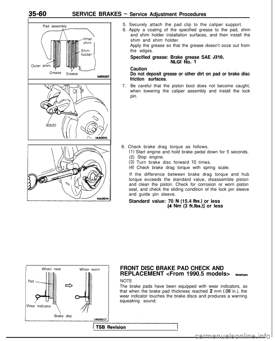
PadWea 5. Securely attach the pad clip to the caliper support.
6. Apply a coating of the specified grease to the pad, shim
and shim holder installation surfaces, and then install the
shim and shim holder.
Apply the grease so that the grease doesn’t ooze out from
the edges.
Specified grease: Brake grease SAE 5310,
NLGI No. 1
Caution
Do not deposit grease or other dirt on pad or brake disc
friction surfaces.
7.Be careful that the piston boot does not become caught,
when lowering the caliper assembly and install the lock pin.
8. Check brake drag torque as follows.
(1) Start engine and hold brake pedal down for 5 seconds.
(2) Stop engine.
(3) Turn brake disc forward IO times.
(4) Check brake drag torque with spring scale.
If the difference between brake drag torque and hub
torque exceeds the standard value, disassemble piston and clean the piston. Check for corrosion or worn piston
seal, and check the sliding condition of the lock pin sleeve
and guide pin sleeve.
Standard value: 70
N (15.4 Ibs.) or less
[4 Nm (3 ftlbs.)]
or less
FRONT DISC BRAKE PAD CHECK AND
REPLACEMENT Y35FaAH
NOTE
The brake pads have been equipped with wear indicators, so
that when the brake pad thickness reached 2 mm
(.08 in.), the
wear indicator touches the brake discs and produces a warning
squeaking sound.
Brake disc
Page 1183 of 1273
35-62SERVICE BRAKES - Service Adjustment Procedures
u /@$fi 14A0Ol5CM-R56W>
II
I
Pad
c
4s14FOO97
!m
!
bly
c
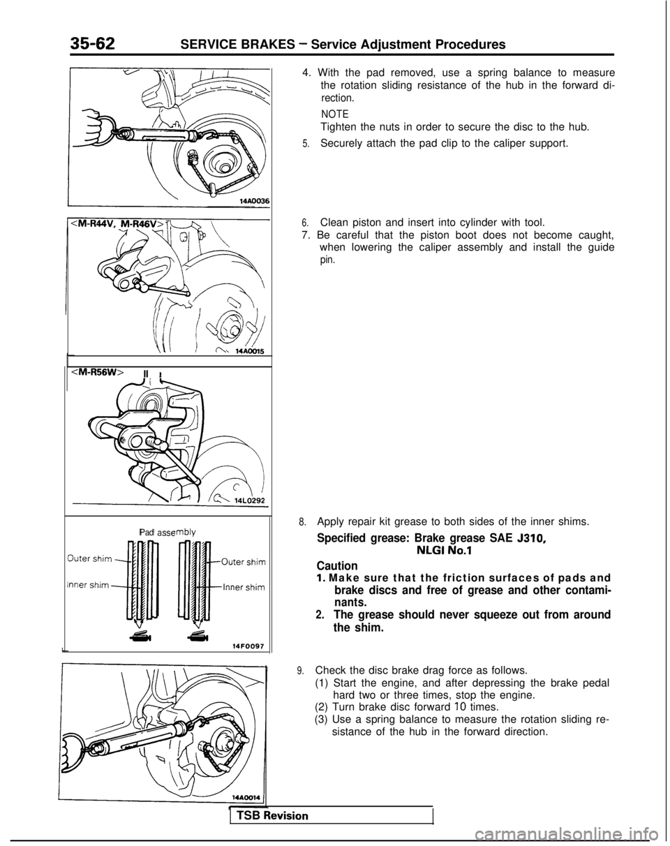
4. With the pad removed, use a spring balance to measure
the rotation sliding resistance of the hub in the forward di-
rection.
NOTE
Tighten the nuts in order to secure the disc to the hub.
5.Securely attach the pad clip to the caliper support.
6.Clean piston and insert into cylinder with tool.
7. Be careful that the piston boot does not become caught, when lowering the caliper assembly and install the guide
pin.
8.Apply repair kit grease to both sides of the inner shims.
Specified grease: Brake grease SAE 5310,
NLGI No.1
Caution
1. Make sure that the friction surfaces of pads and
brake discs and free of grease and other contami-
nants.
2.The grease should never squeeze out from around
the shim.
9.Check the disc brake drag force as follows.
(1) Start the engine, and after depressing the brake pedal hard two or three times, stop the engine.
(2) Turn brake disc forward
10 times.
(3) Use a spring balance to measure the rotation sliding re- sistance of the hub in the forward direction.
TSB
hevision
Page 1186 of 1273
SERVICE BRAKES - Service Adjustment Procedures35-65’
14AO281
WA0204
grooves
Q
0 0
Projection
1410037I-
REAR DISC BRAKE PAD CHECK AND
REPLACEMENT
MBBFUAE
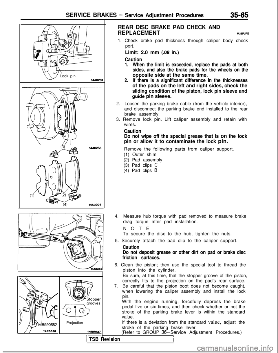
1. Check brake pad thickness through caliper body check port.
Limit: 2.0 mm
(.08 in.)
Caution
1.When the limit is exceeded, replace the pads at both
sides, and also the brake pads for the wheels on the
opposite side at the same time.
2.If there is a significant difference in the thicknesses
of the pads on the left and right sides, check the
sliding condition of the piston, lock pin sleeve and
.guide pin sleeve.
2.Loosen the parking brake cable (from the vehicle interior),
and disconnect the parking brake end installed to the rear brake assembly.
3. Remove lock pin. Lift caliper assembly and retain with wires.
CautionDo not wipe off the special grease that is
on the lock
pin or allow it to contaminate the lock pin.
Remove the following parts from caliper support.
(1) Outer shim
(2) Pad assembly
(3) Pad clips
C
(4) Pad clips B
4.Measure hub torque with pad removed to measure brake
drag torque after pad installation.
NOT
E
To secure the disc to the hub, tighten the nuts.
5. Securely attach the pad clip to the caliper support.
Caution
Do not deposit grease or other dirt on pad or brake disc
friction surfaces.
6. Clean the piston; then use the special tool to thread the piston into the cylinder.
Be sure, at this time, that the stopper groove of the piston,
correctly fits to the projection on the pad’s rear surface.
7.Be careful that the piston boot does not become caught,
when lowering the caliper assembly and install the lock pin.
With the engine running, forcefully depress the brake pedal five or six times, and then check whether or not the
stroke of the parking brake lever is within the standard
value.
If there is a deviation from the standard value, adjust the
stroke of the parking brake lever.
(Refer to GROUP
36-Service Adjustment Procedures.)I) TSB RevisionI
Page 1217 of 1273
35-96SERVICE BRAKES - Front Disc Brake
DISASSEMBLY AND REASSEMBLY
22-32 N
m
16-23
ft.lbs.
22-32 N
m
16-23
ft.lbs.
16
7-9 Nm
5-7
ft.lbs.
I 13
1;
10
6
Seal and boots repair kit
Caliper assembly disassembly steps
I. Lock pin
4*2. Caliper support (Pad, clip, shim).
3. Lock pin sleeve
4. Lock pin boot 5. Guide pin boot
4,6. Boot ring
c*7. Piston boot
+*8. Pistonl * I)* 9. Piston seal10. Caliper body
Pad assembly disassembly steps
I. Lock pin
4*2. Caliper support
(Pad, clip, shim) I
i, Pad assemblyl # 12. Shim holderl + 13. Inner shim
14. Pad assembly
,+ 15. Outer shim 16. Pad clips B17. Pad clips C18. Guide pin19. Guide pin sleeve
20. Support mounting L
5 14UO121
14AO522
Pad repair kit
i4 li1314A0206
Pad repair kit
cl990 models>
14 17 13 121117 15
hake caliper
kit
14A0524
1 TSB Revision1
Page 1219 of 1273
35-98SERVICE BRAKES - Front Disc Brake
pin
Caliper
/support(pad, clip, shim) 1410356
Boot ring14KO5414G0054 14KO57SERVICE POINTS OF DISASSEMBLY M35LFAH
When disassembling the front disc brakes, disassemble both
sides (left and right) as a set.
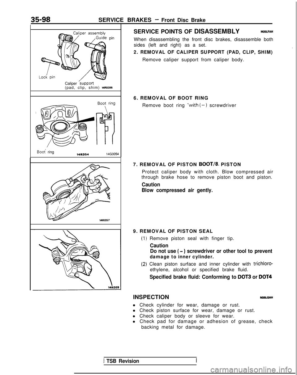
2. REMOVAL OF CALIPER SUPPORT (PAD, CLIP, SHIM)
Remove caliper support from caliper body.
6. REMOVAL OF BOOT RING Remove boot ring
*with (-) screwdriver
7. REMOVAL OF PISTON
BOOT/8. PISTON
Protect caliper body with cloth. Blow compressed air
through brake hose to remove piston boot and piston.
Caution
Blow compressed air gently.
9. REMOVAL OF PISTON SEAL
(1
(2
) Remove piston seal with finger tip.
Caution Do not use
( - ) screwdriver or other tool to prevent
damage to inner cylinder.
I) Clean piston surface and inner cylinder with trichloro-
ethylene, alcohol or specified brake fluid.
Specified brake fluid: Conforming to DOT3 or DOT4
INSPECTIONM35LGAH
l Check cylinder for wear, damage or rust.
l Check piston surface for wear, damage or rust.
l Check caliper body or sleeve for wear.
l Check pad for damage or adhesion of grease, check
backing metal for damage.
1 TSB Revision