1989 MITSUBISHI GALANT fuel filter
[x] Cancel search: fuel filterPage 148 of 1273
13-6
FUEL SYSTEM
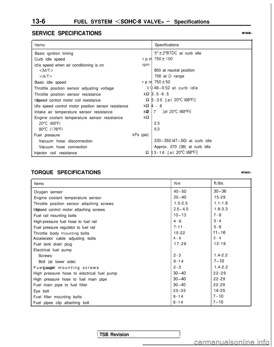
SERVICE SPECIFICATIONSMl3CE.
ItemsSpecifications
Basic ignition timing
5”?2”BTDC at curb idle
Curb idle speed rpm
7502 100Idle
speed when air conditioning is on rpm
-am-r>850 at neutral position
4A>700 at D range
Basic idle speed rpm
750+50
Throttle position sensor adjusting voltageV 0.48-0.52 at curb idl
e
Throttle position sensor resistance
k-2 3.5-6.
5
Idle speed control motor coil resistance
Q 5-35 [at 20°C (68”F)l
Idle
speed control motor position sensor resistance
M-2 4-
6
Intake air temperature sensor resistance kQ 2.7 [at
20°C (68”F)l
Engine coolant temperature sensor resistancekc2
20°C (68°F)2.5
80°C (176°F)0.3
Fuel pressurekPa (psi)
Vacuum hose disconnection
330-350 (47-50) at curb idle
Vacuum hose connection Approx. 270 (38) at curb idle
Injector coil resistance
R 13-16 [at 20°C (68”F)]
TORQUE SPECIFICATIONSMIICC-
Items
Oxygen sensor
Engine coolant temperature sensor
Throttle position sensor attaching screws Idle speed control motor attaching screws
Fuel rail mounting bolts
High-pressure fuel hose to fuel rail
Fuel pressure regulator to fuel rail
Throttle body mounting
bolts
Accelerator cable adjusting bolts
Fuel tank drain plug
Electrical fuel pump Screws
Bolt (at lower side)
Fuel unit mounting screws gauge
High pressure hose to electrical fuel pump
High pressure hose to fuel main pipe
Fuel main pipe to fuel filter
Eye bolt
Fuel filter mounting bolts
Fuel pipes clip attaching boltNmft.lbs.
40-5030-36
20-4015-29
1.5-2.5 1.1-1.8
2.5-4.51.8-3.3
IO-137-
9
4-6 3-4
7-11 5-8
15-22
11-16
4-
6
3-4
17-26 12-19
2-3 1.4-2.2
9-14
7-10
2-
3
1.4-2.2
30-4022-2
9
30-4022-29
30-4022-29
25-3
5
18-25
9-14
7-10
9-1
4
7-10
1 TSB Revision
Page 174 of 1273
13-32
FUEL SYSTEM
FUEL TANK AND FUEL LINEMlBEAAA
Symptom Probable cause Remedy
Engtne malfunctions
Bent or kinked fuel pipe or hose Repair or replace3ue to insufficient fuel
SUPPlYClogged fuel pipe or hoseClean or replace
Clogged fuel filter or in-tank fuel filter Replace
Water in fuel filter Replace the fuel filter or clean the fuel tank
and fuel line
Dirty or rusted fuel tank interior Malfunctioning fuel pump
(Clogged filter in the pump) Clean or replace
Replace
Evaporative emission Mispiping of vapor line
Correct
control system malfunc-
tions (When fuel tank Disconnect vapor line piping joint Correct
filler tube cap is re- moved, pressure releas-
Folded, bent, cracked or clogged vapor line Replace
ng noise is heard) Faulty fuel tank filler tube cap
Malfunctioning fuel tank pressure control
valve Replace
Replace
LL
m ~~ : Paper clip-
F l!;“I /yFp- -
izd--_7-01
A0086SERVICE ADJUSTMENT PROCEDURES
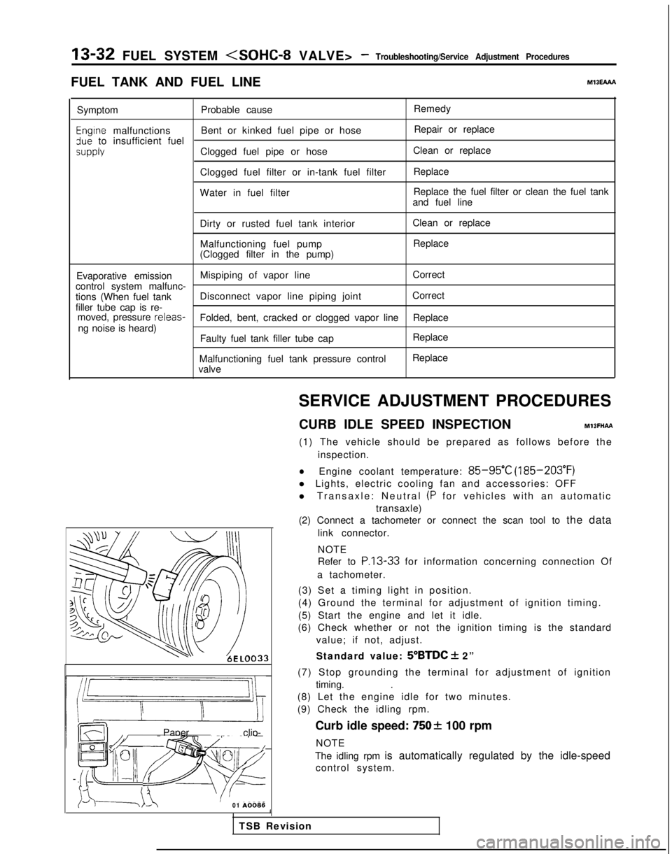
CURB IDLE SPEED INSPECTION
MlBFHAFt
(1) The vehicle should be prepared as follows before the inspection.
lEngine coolant temperature: 85-95°C (185-203°F)
l Lights, electric cooling fan and accessories: OFF
l Transaxle: Neutral
(P for vehicles with an automatic
transaxle)
(2) Connect a tachometer or connect the scan tool to the data
link connector.
NOTE
Refer to
P.13-33 for information concerning connection Of
a tachometer.
(3) Set a timing light in position.
(4) Ground the terminal for adjustment of ignition timing.
(5) Start the engine and let it idle.
(6) Check whether or not the ignition timing is the standard
value; if not, adjust.
Standard value:
5”BTDC + 2”
(7) Stop grounding the terminal for adjustment of ignition timing. .
(8) Let the engine idle for two minutes.
(9) Check the idling rpm.
Curb idle speed:
7502 100 rpm
NOTE
The idling rpm is automatically regulated by the idle-speed control system.
1
TSB Revision
Page 232 of 1273
13-90 FUEL SYSTEM
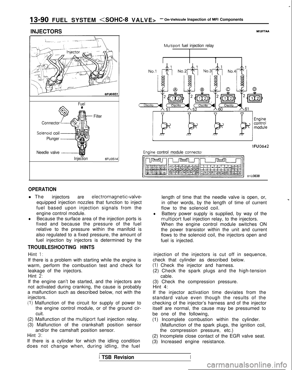
INJECTORS
Fuel
Connector
Solenoid coil
Plunger
Needle valve -----I
InjectionFilter6FUO514
M13rrAA
Multiport
fuel injection relay
No.1 &j No.2& No.3& No,4+
tI
lFUO642
Engine control module connector
CJ=JW=U-I
0 1 LO636
OPERATION
l The
injectorsare electromagnetic-valve-
equipped injection nozzles that function to inject
fuel based upon injection signals from the
engine control module.
lBecause the surface area of the injection ports is
fixed and because the pressure of the fuel
relative to the pressure within the manifold is
also regulated to a fixed pressure, the amount of
fuel injection by injectors is determined by the
TROUBLESHOOTING HINTS
Hint 1:
If there is a problem with starting while the engine is
warm, perform the combustion test and check for leakage of the injectors.
Hint
2,
If the engine can’t be started, and the injectors are
not activated during cranking, the cause is probably
a malfunction such as described below, not with the
injectors.
(I) Malfunction of the circuit for supply of power to the engine control module, or of the ground cir-
cuit.
(2) Malfunction of the multiport fuel injection relay.
(3) Malfunction of the crankshaft position sensor and/or the camshaft position sensor.
Hint
3.
If there is a cylinder for which the idling condition
does not change when, during idling, the fuel length of time that the needle valve is open, or,
in other words, by the length of time of current
~-
flow to the solenoid coil.
lBattery power supply is supplied, by way of the
multiport fuel injection relay, to the injectors.
When the engine control module switches ON
the power transistor within the unit and current
flows to the solenoid coil, the injectors open and
fuel is injected.
injection of the injectors is cut off in sequence,
check that cylinder as described below.
(1) Check the injector and harness.
(2) Check the spark plugs and the high-tension
cable.
(3) Check the compression pressure. Hint 4:
If the injector activation time deviates from the
standard value even though the results of the
checking of the injector’s harness and of the injector itself are normal, the cause may be pressumed to
be one of the following,
(1) Incomplete combustion within the cylinder. (Malfunction of the spark plugs, the ignition coil,
the compression pressure, etc.)
(2) Incomplete close contact of the EGR valve seat.
(3) Increased engine resistance.
1 TSB RevisionI
Page 246 of 1273
13-I 04 FUEL SYSTEM
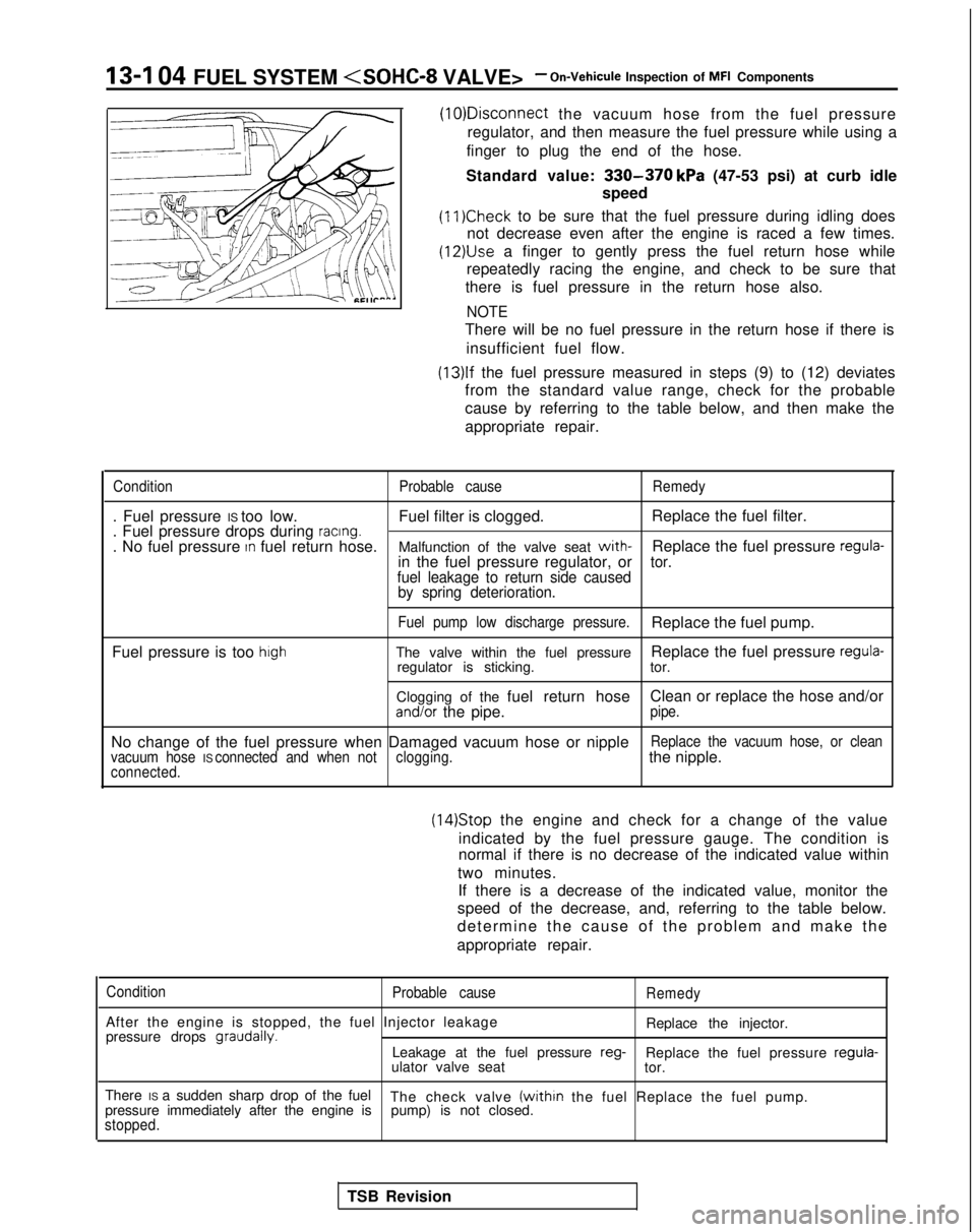
the vacuum hose from the fuel pressure
regulator, and then measure the fuel pressure while using a
finger to plug the end of the hose.
Standard value:
330-370 kPa (47-53 psi) at curb idle
speed
(11)Check to be sure that the fuel pressure during idling does
not decrease even after the engine is raced a few times.
(12)&e a finger to gently press the fuel return hose while
repeatedly racing the engine, and check to be sure that
there is fuel pressure in the return hose also.
NOTE
There will be no fuel pressure in the return hose if there is
insufficient fuel flow.
(13)lf the fuel pressure measured in steps (9) to (12) deviates
from the standard value range, check for the probable
cause by referring to the table below, and then make the
appropriate repair.
Condition Probable causeRemedy
. Fuel pressure IS too low. Fuel filter is clogged.Replace the fuel filter.
. Fuel pressure drops during racing.. No fuel pressure In fuel return hose. Malfunction of the valve seat with-Replace the fuel pressure regula-in the fuel pressure regulator, ortor.
fuel leakage to return side caused by spring deterioration.
Fuel pump low discharge pressure.Replace the fuel pump.
Fuel pressure is too
highThe valve within the fuel pressure Replace the fuel pressure regula-regulator is sticking.
tor.
Clogging of the fuel return hose Clean or replace the hose and/or
and/or the pipe.pipe.
No change of the fuel pressure when Damaged vacuum hose or nippleReplace the vacuum hose, or clean
vacuum hose IS connected and when not clogging.the nipple.connected.
(14)Stop the engine and check for a change of the value
indicated by the fuel pressure gauge. The condition is
normal if there is no decrease of the indicated value within
two minutes. If there is a decrease of the indicated value, monitor the
speed of the decrease, and, referring to the table below.
determine the cause of the problem and make the
appropriate repair.
Condition Probable cause
After the engine is stopped, the fuel Injector leakage
pressure drops graudally.
Remedy
Replace the injector.
Leakage at the fuel pressure reg-
Replace the fuel pressure regula-
ulator valve seat tor.
There IS a sudden sharp drop of the fuel The check valve
(within the fuel Replace the fuel pump.
pressure immediately after the engine is pump) is not closed.
stopped.
TSB Revision
Page 255 of 1273
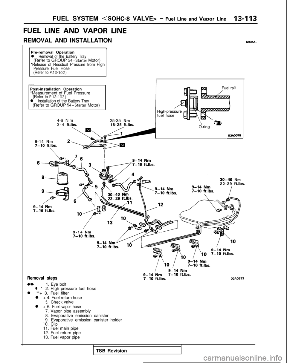
FUEL SYSTEM (SOHC-8 VALVE> - Fuel Line and VaDor Line13-l 13
FUEL LINE
AND
VAPOR LINE
REMOVAL AND INSTALLATION M13KA-
IIPre-removal Operationl Removal of the Battery Tray(Refer to GROUP
54-Starter
Motor)*Release of Residual Pressure from High
Pressure Fuel Hose
(Refer to
P.13-102.)
-
Post-installation Operation *Measurement of Fuel Pressure
(Refer to P.13-103.)l Installation of the Battery Tray(Refer to GROUP 54-Starter
Motor)
4-6 Nm
3-4 ft.lbs.
25-35 Nm
18-25
ftlbs.
9-14 Nm7-10 ftlbs.
\
&ring‘lm
30-40Nm
22-2
9
ft.lbs.
9-1
4
Nm
7-10klbs.
Removal steps
**1. Eye boltl *2. High pressure fuel hose
l **+ 3. Fuel filter l + 4. Fuel return hose
5.Checkvalvel + 6. Fuel vapor hose7. Vapor pipe assembly
8. Evaporative emission canister
9. Evaporative emission canister holder
10.Clip11. Fuel main pipe
12. Fuel return pipe
13. Fuel vapor pipe
7-10 ft.lbs.03AO233
TSB Revision
Page 256 of 1273
13-114FUEL SYSTEM
SERVICE POINTS OF REMOVAL
MlIKBAM
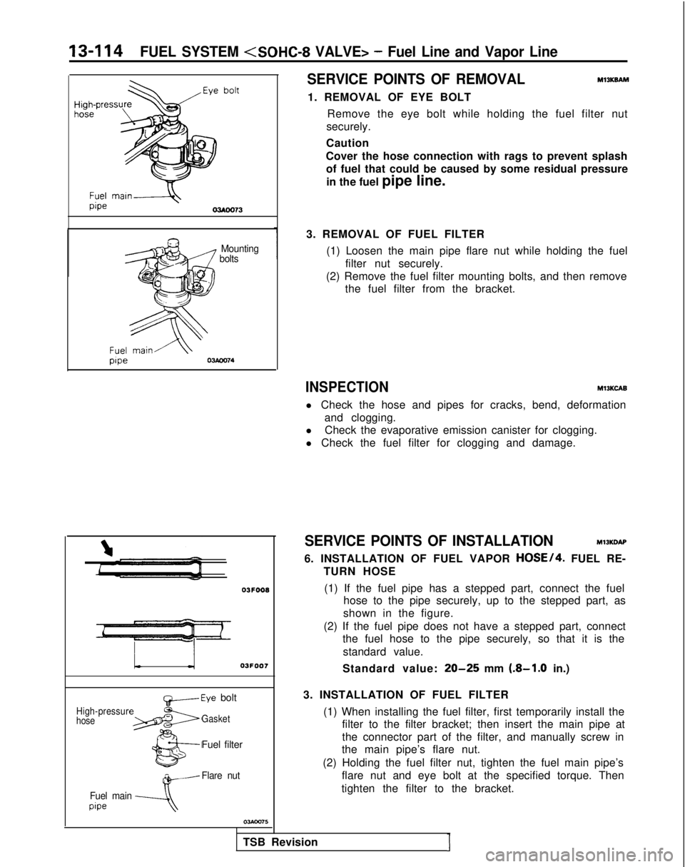
1. REMOVAL OF EYE BOLT Remove the eye bolt while holding the fuel filter nut
securely.
Caution
Cover the hose connection with rags to prevent splash of fuel that could be caused by some residual pressure
in the fuel pipe line.
I Mounting bolts
1
OJFOOB
L03FOO7
High-pressur
hose
~-Eye bolt
Gasket
Fuel filter
w-Flare nut
Fuel main
pipe---A
3. REMOVAL OF FUEL FILTER (1) Loosen the main pipe flare nut while holding the fuelfilter nut securely.
(2) Remove the fuel filter mounting bolts, and then remove the fuel filter from the bracket.
INSPECTIONM13KCAB
l Check the hose and pipes for cracks, bend, deformation
and clogging.
l Check the evaporative emission canister for clogging.
l Check the fuel filter for clogging and damage.
TSB Revision
I
SERVICE POINTS OF INSTALLATION Ml3KDAP
6. INSTALLATION OF FUEL VAPOR
HOSE/4. FUEL RE-
TURN HOSE
(1) If the fuel pipe has a stepped part, connect the fuel hose to the pipe securely, up to the stepped part, as
shown in the figure.
(2) If the fuel pipe does not have a stepped part, connect the fuel hose to the pipe securely, so that it is the
standard value.
Standard value:
20-25 mm (.8-1.0 in.)
3. INSTALLATION OF FUEL FILTER (1) When installing the fuel filter, first temporarily install thefilter to the filter bracket; then insert the main pipe at
the connector part of the filter, and manually screw in
the main pipe’s flare nut.
(2) Holding the fuel filter nut, tighten the fuel main pipe’s flare nut and eye bolt at the specified torque. Then
tighten the filter to the bracket.
Page 257 of 1273
FUEL SYSTEM
Higt
fuel
&ring Oi’
FUEL FILTER
REMOVAL AND INSTALLATION
~zgz&i&r” 1@Release of Residual Pressure from High
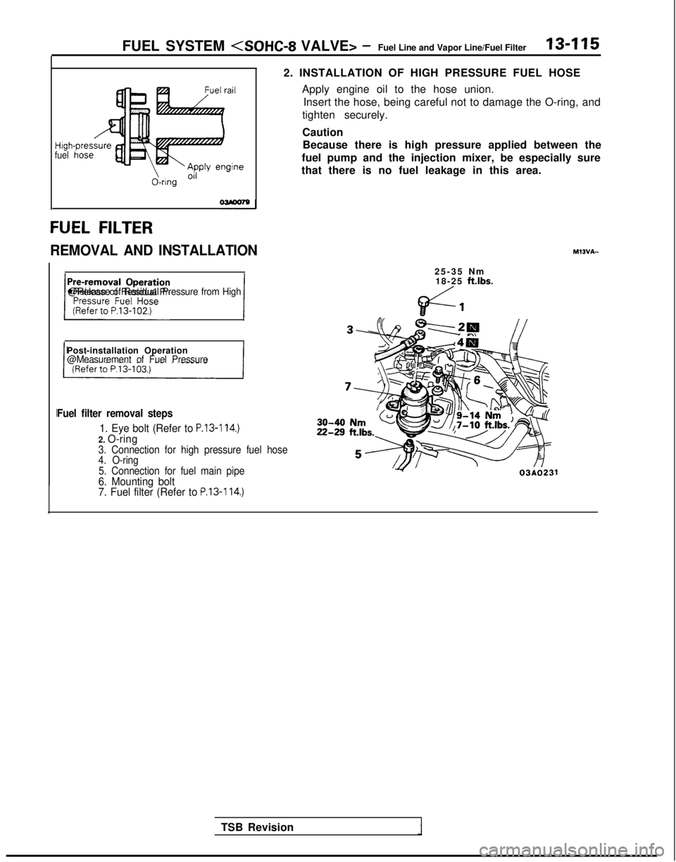
2. INSTALLATION OF HIGH PRESSURE FUEL HOSE
Apply engine oil to the hose union.Insert the hose, being careful not to damage the O-ring, and
tighten securely.
Caution Because there is high pressure applied between the
fuel pump and the injection mixer, be especially sure
that there is no fuel leakage in this area.
25-35 N
m
18-25
ft.lbs.
Post-installation Operation@Measurement of Fuel Pressure
Fuel filter removal steps
1. Eye bolt (Refer to P.13-114.)2. O-ring3. Connection for high pressure fuel hose
4. O-ring
5. Connection for fuel main pipe
6. Mounting bolt
7. Fuel filter (Refer to P.13-114.)
TSB Revision 03AO231
Page 260 of 1273
13418FUEL SYSTEM (SOHC-16 VALVE> - Specifications
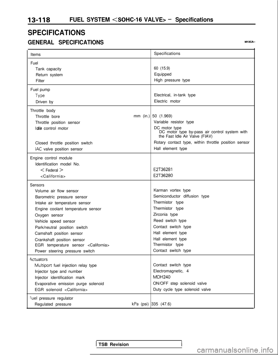
SPECIFICATIONS
GENERAL SPECIFICATIONSMISCA-
Items
Fuel
Tank capacityReturn system
Filter
Fuel pump Type
Driven by
Throttle body Throttle bore
Throttle position sensor Idle air control motor
Closed throttle position switch
IAC valve position sensor
Engine control module Identification model No.
< Federal >
Sensors
Volume air flow sensorBarometric pressure sensor
Intake air temperature sensor
Engine coolant temperature sensor
Oxygen sensor
Vehicle speed sensor
Park/neutral position switch
Camshaft position sensor
Crankshaft position sensor EGR temperature sensor
Power steering pressure switch
Cvctuators
Multiport fuel injection relay type
Injector type and number
Injector identification mark
Evaporative emission purge solenoid
EGR solenoid
pressure regulator
Regulated pressure Specifications
60 (15.9)
Equipped
High pressure type
Electrical, in-tank type
Electric motor
mm (in.) 50 (1.969) Variable resistor typeDC motor type DC motor type by-pass air control system with
the Fast Idle Air Valve (FIAV)
Rotary contact type, within throttle position sensor
Hall element type
E2T36281 E2T36280
Karman vortex type
Semiconductor diffusion type
Thermistor type
Thermistor type Zirconia type
Reed switch type
Contact switch type Hall element type
Hall element type
Thermistor type
Contact switch type
Contact switch type
Electromagnetic, 4 MDH240
ON/OFF step solenoid valve Duty cycle type solenoid valve
kPa (psi) 335 (47.6)
1 TSB Revision