Page 580 of 1273
14-28COOLING - Water Hose and Water Pipe
WATER HOSE AND WATER PIPE
Pre-removal and Post-installation Operation 1eDraining and Filling of the Engine Coolant
(Refer to GROUP 00-Maintenance Service.)
*Draining and Filling of the Engine Oil
(Refer to GROUP 11 -Service Adjustment Pro-
cedures.)
REMOVAL AND INSTALLATION
12-15 Nm
9-l 1 ft.lbs.25-30 Nm18-24 ft.lbs.
M141A-C
‘1
Flare nut 55-65
N
m
/-A 40-47 ft.lbs.
12-15 Nk9-11
ftlbs.
30-40 Nm
22-29 ft.lbs:
,“k.
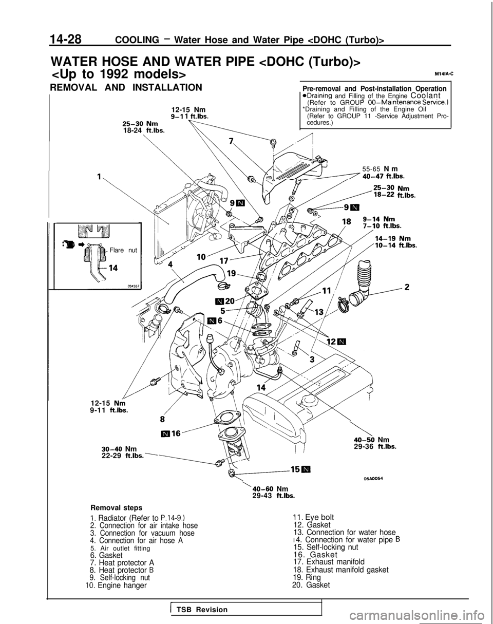
Removal steps
I. Radiator (Refer to P.14-9.)2. Connection for air intake hose
3. Connection for vacuum hose
4. Connection for air hose A
5. Air outlet fitting6. Gasket
7. Heat protector A
8. Heat protector
B9. Self-locking nut10. Engine hanger
\40-50 Nm
29-36 ftlbs.
05Aoo54\40-60 Nm
29-43 ft.lbs.
II. Eye bolt12. Gasket
13. Connection for water hose
I 4. Connection for water pipe B15. Self-locking nut16. Gasket -17. Exhaust manifold
18. Exhaust manifold gasket
19. Ring
20. Gasket
i TSB Revision
Page 598 of 1273
15-12INTAKE AND EXHAUST - Charge Air Cooler
CHARGE AIR COOLER
REMOVAL AND INSTALLATION
A
12-15 Nm&-2-s--
TX.<.\-@
\\’ 19-11 ft.lbs.,_
12-15 Nm
9-11 ftlbs.
12-15-Nm9-l 1 ft.lbs.
05A0191
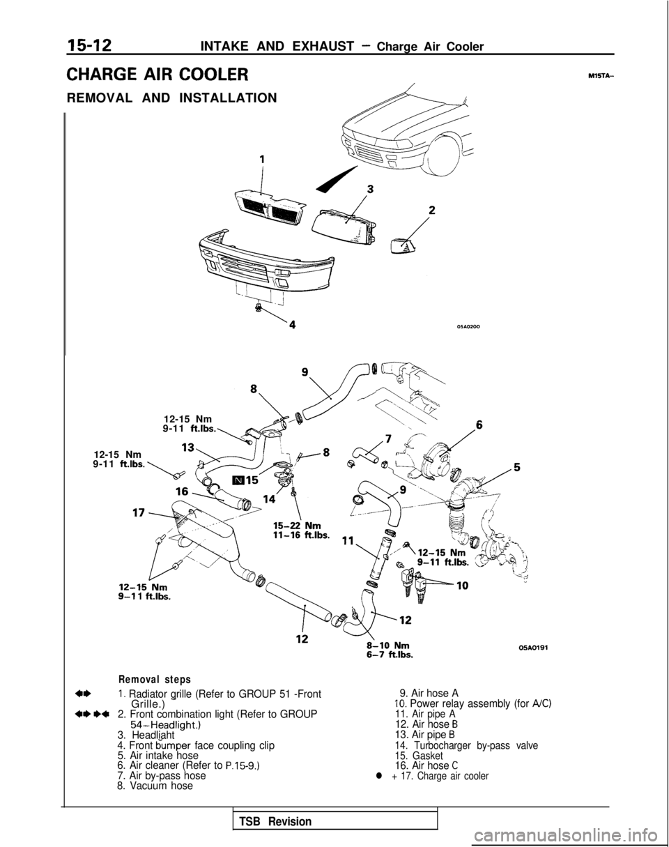
Removal steps
1. Radiator grille (Refer to GROUP 51 -FrontGrille.) -+e *+2. Front combination light (Refer to GROUP
54-Headlight.)
3. Headliaht
4. Front bumper face coupling clip
5. Air intake hose
6. Air cleaner (Refer to
P.15-9.)7. Air by-pass hose
8. Vacuum hose 9. Air hose A
10. Power relay assembly (for A/C)11. Air pipe A12. Air hose B13. Air pipe B14. Turbocharger by-pass valve
15. Gasket
16. Air hose Cl + 17. Charge air cooler
MXiTA-
TSB Revision
Page 600 of 1273
15-14INTAKE AND EXHAUST -Intake Manifold
INTAKE MANIFOLD
{EMOVAL
AND INSTALLATION
4-6 Nm
Y “1 ~/c 3-4 ft.‘bs.At
4-6 ‘Nm
3-4 ft.lbs.
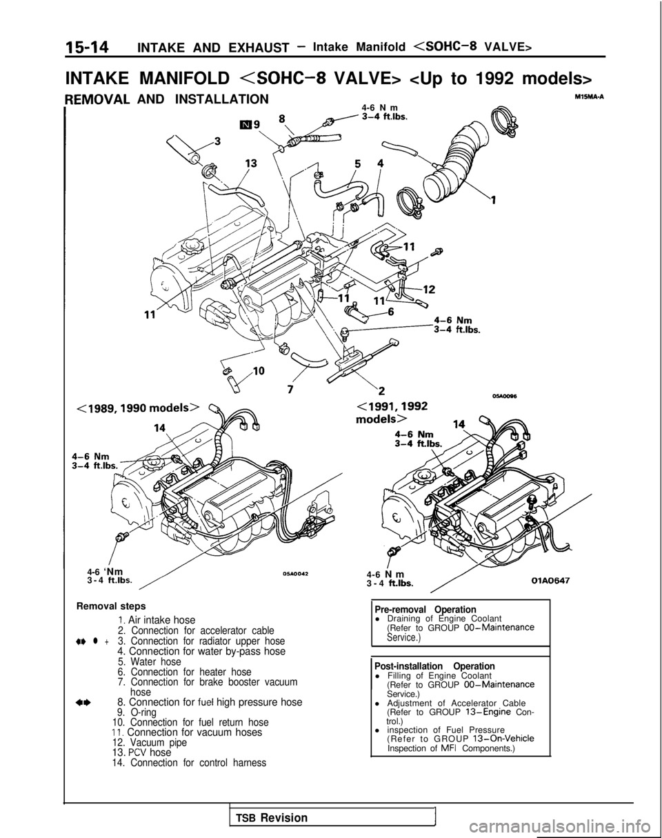
Removal steps
I. Air intake hose2. Connection for accelerator cable+e l +3. Connection for radiator upper hose4. Connection for water by-pass hose5. Water hose
6. Connection for heater hose
7. Connection for brake booster vacuum hose
8. Connection for fuel high pressure hose9. O-ring
10. Connection for fuel return hose
II. Connection for vacuum hoses12. Vacuum pipe13. PCV hose14. Connection for control harness
MlSMA-A
4-6 N
m
3-4
ft.lbs.OlA0647
Pre-removal Operationl Draining of Engine Coolant
(Refer to GROUP 00-MaintenanceService.)
Post-installation Operationl Filling of Engine Coolant(Refer to GROUP 00-MaintenanceService.)
l Adjustment of Accelerator Cable (Refer to GROUP
13-Engine Con-
trol.)
l inspection of Fuel Pressure
(Refer to GROUP
13-On-VehicleInspection of MFI Components.)
TSB Revision1
Page 602 of 1273
15-16INTAKE AND EXHAUST- Intake Manifold
05AOO89
I05A0081
(
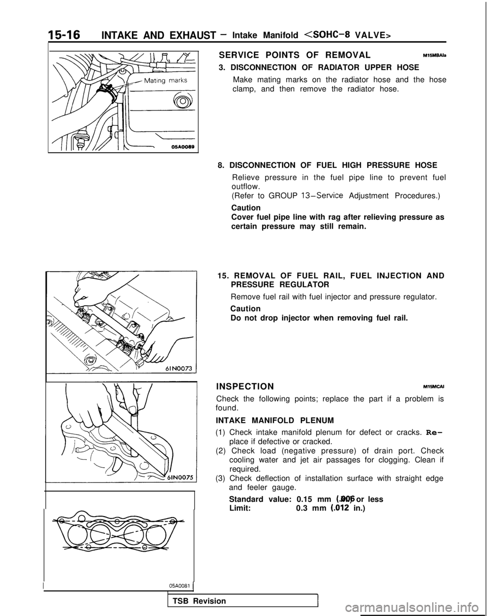
SERVICE POINTS OF REMOVALM15M9Ah
3. DISCONNECTION OF RADIATOR UPPER HOSE
Make mating marks on the radiator hose and the hose
clamp, and then remove the radiator hose.
8. DISCONNECTION OF FUEL HIGH PRESSURE HOSE Relieve pressure in the fuel pipe line to prevent fuel
outflow.
(Refer to GROUP
13-Service Adjustment Procedures.)
Caution
Cover fuel pipe line with rag after relieving pressure as
certain pressure may still remain.
15. REMOVAL OF FUEL RAIL, FUEL INJECTION AND PRESSURE REGULATOR
Remove fuel rail with fuel injector and pressure regulator.
Caution Do not drop injector when removing fuel rail.
INSPECTION
MlSMCAI
Check the following points; replace the part if a problem is
found.
INTAKE MANIFOLD PLENUM
(1) Check intake manifold plenum for defect or cracks. Re- place if defective or cracked.
(2) Check load (negative pressure) of drain port. Check cooling water and jet air passages for clogging. Clean if
required.
(3) Check deflection of installation surface with straight edge and feeler gauge.
Standard value: 0.15 mm (.006 in.) or less
Limit: 0.3 mm
(.012 in.)
1
TSB Revision
Page 603 of 1273
INTAKE AND EXHAUST -Intake Manifold
>
15-17
\
05A0074
TSB Revision
I
INTAKE MANIFOLD
(1) Check for damage or cracking of any part.
(2) Check load (negative pressure) of drain port. Check cooling water and jet air passages for clogging. Clean if
required.
(3) Check deflection of installation surface with straight edge
and feeler gauge.
Standard value: 0.15 mm I.006
in.) or less
Limit: 0.3
mm
(.012 in.1
SERVICE POINTS OF INSTALLATION,MlSMDAK
15. INSTALLATION OF FUEL RAIL, FUEL INJECTOR
AND PRESSURE REGULATOR
Caution
Be careful not to drop the injector when the fuel rail
is installed.
3. CONNECTION OF RADIATOR UPPER HOSE Align the mating marks on the radiator hose and the hoseclamp and install; then apply pressure where shown by
the arrows in the illustration so that the clamp is correctly
seated at the clamp’s previous trace indentations.
Caution Be absolutely sure that the hose clamp is correctly
seated to its previous trace indentations.
Page 610 of 1273
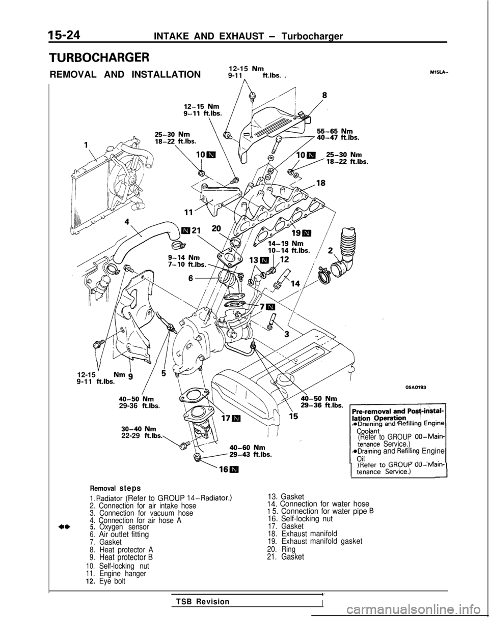
15-24INTAKE AND EXHAUST - Turbocharger
TURBOCHARGER
REMOVAL AND INSTALLATION12-15 Nm9-11 ft.lbs. )n
MlSLA-
40-47 ftlbs.
v I”12-15 Nm g
9-11 ftlbs.
i40-50 Nm29-36 ft.lbs.
05A0193
30-40 Nm22-29 ftlbs. *Draining
andRefilling Engine
(Refer to GROUPOO-Main-tenance Service.)aDraining and Refilling Engine
---. .- _^ . ._;_I(Refer to CiKUUi-’
UU-M~III-11
tenance Service.)-I
Removal steps
1.
Radiator (Refer to GROUP 14-Radiator.)
13. Gasket2. Connection for air intake hose14. Connection for water hose
3. Connection for vacuum hoseI 5. Connection for water pipe B
4. Connection for air hose A16. Self-locking nut
4*5.Oxygen sensor17.Gasket
6.Air outlet fitting18.Exhaust
manifold
7.Gasket19.Exhaustmanifold
gasket
8.Heat protector A 20.Ring
9.Heat protector B21.Gasket
10.Self-locking nut11.Engine hanger
12. Eye bolt
1‘
TSB RevisionI
Page 617 of 1273
INTAKE AND EXHAUST -Exhaust Manifold 15-31
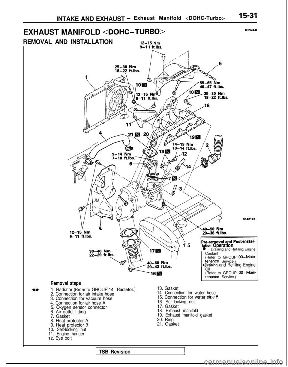
EXHAUST MANIFOLD
REMOVAL AND INSTALLATION
12-15
Nm
Removal
12-15.Nm - g-11
ft.lbs.
steps
9-l 1 ftlbs.
lh ./-I
‘Uc Ml5NA.C
05AO192
Coolant
(Refer to GROUP
00-Maimtenance Service.)eDraining and Refilling Engine
1. Radiator (Referto GROUP 14-Radiator.)
2. Connection for air intake hose
3. Connection for vacuum hose
4. Connection for air hose A 5. Oxygen sensor connector
6. Air outlet fitting
7. Gasket
8. Heat protector A 9. Heat protector
B10. Self-locking nut
11. Engine hanger
12. Eye bolt
‘\!I 1
5
Ilation Operationl Draining and Refilling Engine
Oil
-
(Refer to GROUP 00-Main.tenance Service.)
13. Gasket14. Connection for water hose15. Connection for water pipe.B16. Self-locking nut17. Gasket18. Exhaust manifold
19. Exhaust manifold gasket
20. Ring
21. Gasket
TSB Revision1
Page 806 of 1273
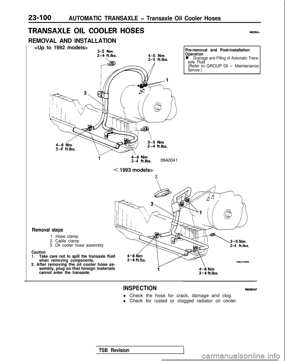
23-100AUTOMATIC TRANSAXLE - Transaxle Oil Cooler Hoses
TRANSAXLE OIL COOLER HOSES
REMOVAL AND INSTALLATION
3-5 Nm2-4 ft.lbs.4-6 Nm\3-4 ft.lbs.
3-4 ft.lbs.
4-6 Nm3-4 ft.lbs.09A0041
< 1993 models>
2Pre-removal and Post-installation
Operationl
Drainage and Filling of Automatic Trans-axle Fluid(Refer to GROUP 00 - MaintenanceService.)
Removal steps
1. Hose clamp
2. Cable clamp
3. Oil cooler hose assembly
Caution1.Take care not to spill the transaxle fluidwhen removing components.2. After removing the oil cooler hose as- sembly, plug so that foreign materials
cannot enter the transaxle.
2-4 ftlbs.
bs.I /-\nhu-l,no
INSPECTION
l Check the hose for crack, damage and clog.
l Check for rusted or clogged radiator oil cooler.
TSB Revision
 Check for damage or cracking of any part.
(2) Check load (negative pressure) of drain port. Chec")