1989 MITSUBISHI GALANT compression ratio
[x] Cancel search: compression ratioPage 207 of 1273
FUEL SYSTEM
(1) Improper adjustment of the basic idling speed.
(2) Deposits adhering to the ttirottle valve.
(3) Air being taken into the intake manifold due to a gasket leak, etc.
OPERATION
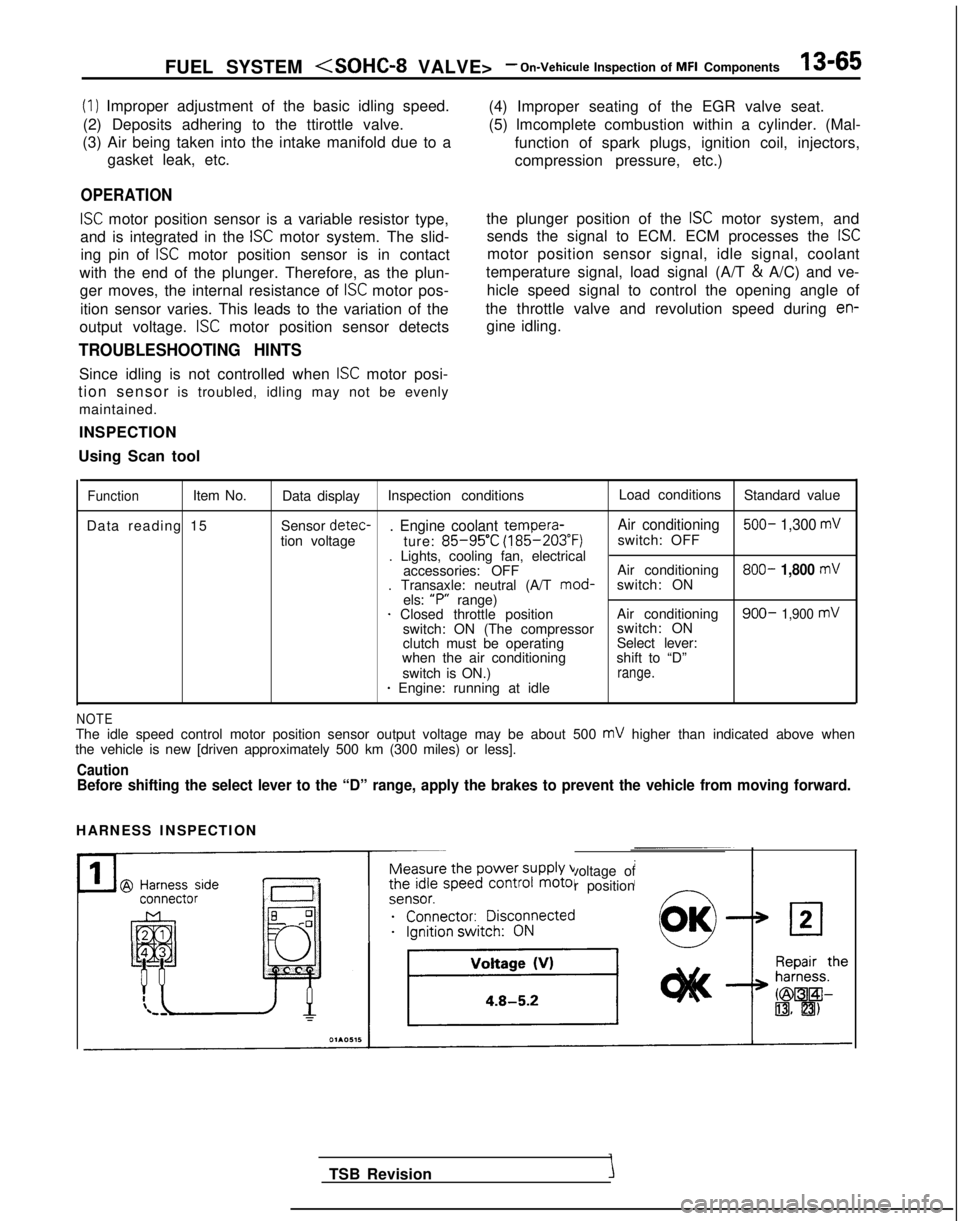
ISC motor position sensor is a variable resistor type,
and is integrated in the
ISC motor system. The slid-
ing pin of
ISC motor position sensor is in contact
with the end of the plunger. Therefore, as the plun- ger moves, the internal resistance of
ISC motor pos-
ition sensor varies. This leads to the variation of the (4) Improper seating of the EGR valve seat.
(5) lmcomplete combustion within a cylinder. (Mal-
function of spark plugs, ignition coil, injectors,
compression pressure, etc.)
the plunger position of the
ISC motor system, and
sends the signal to ECM. ECM processes the
ISC
motor position sensor signal, idle signal, coolant
temperature signal, load signal (A/T &
A/C) and ve-
hicle speed signal to control the opening angle of
the throttle valve and revolution speed during
en-
output voltage. ISC motor position sensor detects gine idling.
TROUBLESHOOTING HINTS
Since idling is not controlled when ISC motor posi-
tion sensor is troubled, idling may not be evenly
maintained.
INSPECTION
Using Scan tool
FunctionItem No. Data display Inspection conditions Load conditions
Standard value
Data reading 15 Sensor detec-
. Engine coolant tempera-
Air conditioning 500- 1,300 mV
tion voltage
ture: 85-95’C (185-203°F)
switch: OFF
. Lights, cooling fan, electrical accessories: OFF Air conditioning 800-
1,800 mV. Transaxle: neutral (A/T
mod-
switch: ON
els: “P”
range)
1 Closed throttle position Air conditioning900- 1,900 mVswitch: ON (The compressorswitch: ON
clutch must be operating Select lever:
when the air conditioning shift to “D”
switch is ON.)
range.* Engine: running at idle
NOTEThe idle speed control motor position sensor output voltage may be about\
500 mV higher than indicated above when
the vehicle is new [driven approximately 500 km (300 miles) or less].
CautionBefore shifting the select lever to the “D” range, apply the brake\
s to prevent the vehicle from moving forward.
HARNESS INSPECTION
Measure the power supply voltage of
the idle speed control motor position
ei;;;it;;sco$ected
__...._ -.-
TSB Revision
Page 232 of 1273
13-90 FUEL SYSTEM
INJECTORS
Fuel
Connector
Solenoid coil
Plunger
Needle valve -----I
InjectionFilter6FUO514
M13rrAA
Multiport
fuel injection relay
No.1 &j No.2& No.3& No,4+
tI
lFUO642
Engine control module connector
CJ=JW=U-I
0 1 LO636
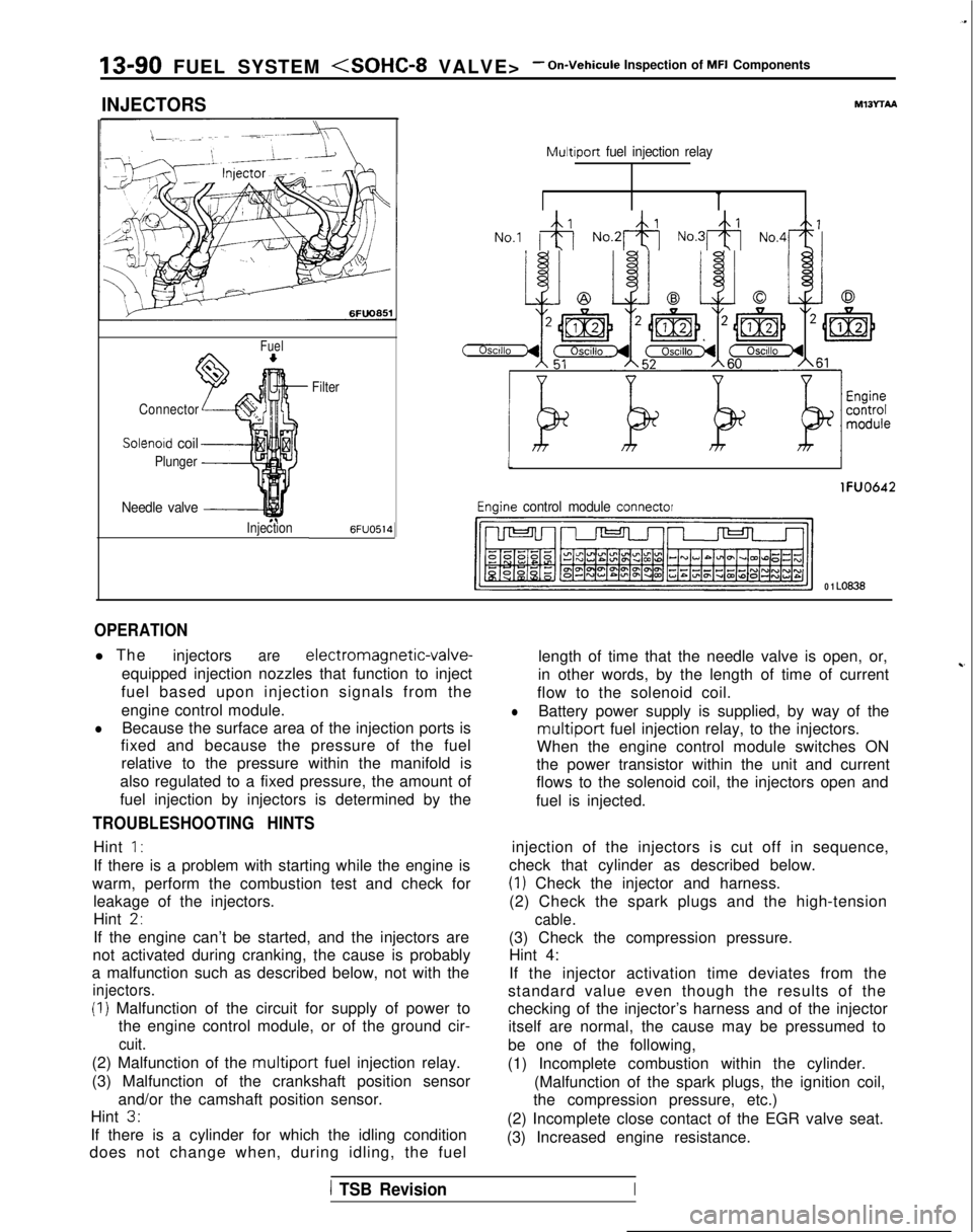
OPERATION
l The
injectorsare electromagnetic-valve-
equipped injection nozzles that function to inject
fuel based upon injection signals from the
engine control module.
lBecause the surface area of the injection ports is
fixed and because the pressure of the fuel
relative to the pressure within the manifold is
also regulated to a fixed pressure, the amount of
fuel injection by injectors is determined by the
TROUBLESHOOTING HINTS
Hint 1:
If there is a problem with starting while the engine is
warm, perform the combustion test and check for leakage of the injectors.
Hint
2,
If the engine can’t be started, and the injectors are
not activated during cranking, the cause is probably
a malfunction such as described below, not with the
injectors.
(I) Malfunction of the circuit for supply of power to the engine control module, or of the ground cir-
cuit.
(2) Malfunction of the multiport fuel injection relay.
(3) Malfunction of the crankshaft position sensor and/or the camshaft position sensor.
Hint
3.
If there is a cylinder for which the idling condition
does not change when, during idling, the fuel length of time that the needle valve is open, or,
in other words, by the length of time of current
~-
flow to the solenoid coil.
lBattery power supply is supplied, by way of the
multiport fuel injection relay, to the injectors.
When the engine control module switches ON
the power transistor within the unit and current
flows to the solenoid coil, the injectors open and
fuel is injected.
injection of the injectors is cut off in sequence,
check that cylinder as described below.
(1) Check the injector and harness.
(2) Check the spark plugs and the high-tension
cable.
(3) Check the compression pressure. Hint 4:
If the injector activation time deviates from the
standard value even though the results of the
checking of the injector’s harness and of the injector itself are normal, the cause may be pressumed to
be one of the following,
(1) Incomplete combustion within the cylinder. (Malfunction of the spark plugs, the ignition coil,
the compression pressure, etc.)
(2) Incomplete close contact of the EGR valve seat.
(3) Increased engine resistance.
1 TSB RevisionI
Page 307 of 1273
FUEL SYSTEM (SOHC-16 VALVE> - %$k%lnspectio” Of MF’13-165
CAMSHAFT POSITION SENSOR
@ Equipment side
connector
Output
characteristic PJ)
‘One rotation of distributor
@ Harness stdeconnector
lgnltion switch (IG,)
Distributor pistributor& 2 ,
I
z
Camshaft
position
Engine
control
module
Engine control module connector
TSB RevisionI
7FUO6539FuOO27
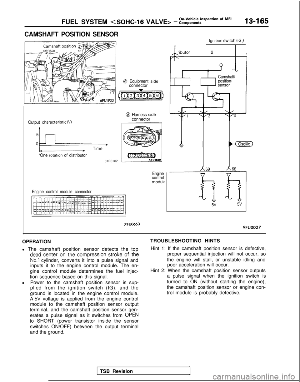
OPERATION
l The camshaft position sensor detects the top dead
center
on the
compression
stroke
of
the
No.1 cylinder, converts it into a pulse signal and
inputs it to the engine control module. The en-
gine control module determines the fuel injec-
tion sequence based on this signal.
l Power to the camshaft position sensor is sup-
plied from the ignition switch (IG), and the
ground is located in the engine control module.
A
5V voltage is applied from the engine control
module to the camshaft position sensor output
terminal, and the camshaft position sensor gen-
erates a pulse signal as it switches from OPEN
to SHORT (power transistor inside the sensor
switches ON/OFF) between the output terminal
and the ground. TROUBLESHOOTING HINTS
Hint 1: If the camshaft position sensor is defective, proper sequential injection will not occur, so
the engine will stall, or unstable idling and poor acceleration will occur.
Hint 2: When the camshaft position sensor outputs a pulse signal when the ignition switch is
turned to ON (without starting the engine),
the camshaft position sensor or engine con-
trol module is probably defective.
Page 326 of 1273
13-184
On-Vehicle Inspection of MFI
FUEL SYSTEM (SOHC-16 VALVE> - Components
IDLE AIR CONTROL MOTOR (DC MOTOR)
@ Harness sideconnectorI L
[@Ex@ziJ 1
5ELWOlJ
j
e;
j 55ww3 )A’,’/
@ Equipment sideconnector
Engine control module
Idle air control motor
6FU1734
Engine control module connector
7FUCJG3
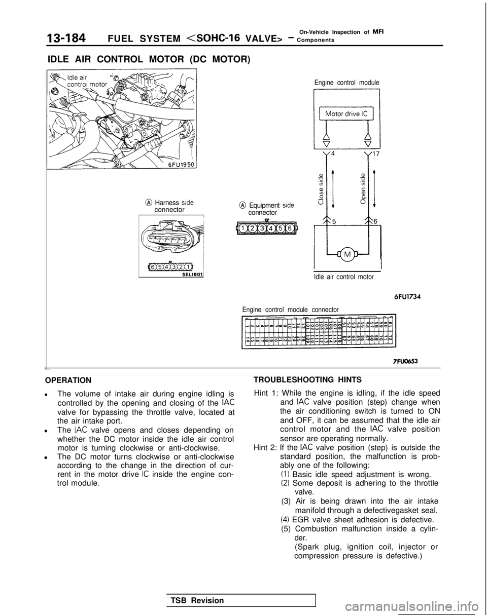
OPERATION
lThe volume of intake air during engine idling is controlled by the opening and closing of the
IAC
valve for bypassing the throttle valve, located at
the air intake port.
lThe IAC valve opens and closes depending on
whether the DC motor inside the idle air control motor is turning clockwise or anti-clockwise.
l The DC motor turns clockwise or anti-clockwise
according to the change in the direction of cur-
rent in the motor drive
IC inside the engine con-
trol module. TROUBLESHOOTING HINTS
Hint 1: While the engine is idling, if the idle speed and
IAC valve position (step) change when
the air conditioning switch is turned to ON
and OFF, it can be assumed that the idle air
control motor and the
IAC valve position
sensor are operating normally.
Hint 2: If the
IAC valve position (step) is outside the
standard position, the malfunction is prob-
ably one of the following: (I)
Basic idle speed adjustment is wrong.
(2) Some deposit is adhering to the throttle
valve.
(3) Air is being drawn into the air intake
manifold through a defectivegasket seal.
(4) EGR valve sheet adhesion is defective.
(5) Combustion malfunction inside a cylin-
der.
(Spark plug, ignition coil, injector or
compression pressure is defective.)
TSB Revision
Page 403 of 1273
FUEL SYSTEM
VOLUME AIR FLOW SENSORMlWFAAs
/
side
@Harness side connector
I@ Harness sideconnector
Fnnine control module connector
Multiport fuel
The area enclosed with :I: is injection relay
applicable only for Turbo vehicle.
I
@I Component connector (Filter reset circuit)
Engine control module
6FU1537
Intake air amount (Wsec)
162451
OlLO838
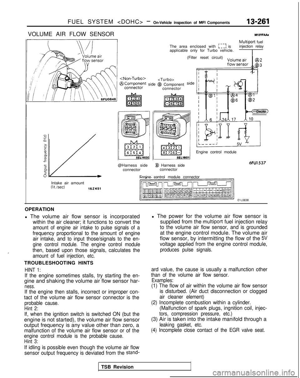
OPERATION
l The volume air flow sensor is incorporated
within the air cleaner; it functions to convert the
amount of engine air intake to pulse signals of a
frequency proportional to the amount of engine air intake, and to input those/signals to the en-
gine control module. The engine control module
then, based upon those signals, calculates the
amount of fuel injection, etc.
TROUBLESHOOTING HINTS
HINT 1:
If the engine sometimes stalls, try starting the en-
gine and shaking the volume air flow sensor har-
ness.
If the engine then stalls, incorrect or improper con-
tact of the volume air flow sensor connector is the
probable cause.
Hint 2:
If, when the ignition switch is switched ON (but the
engine is not started), the volume air flow sensor
output frequency is any value other than zero, a
malfunction of the volume air flow sensor or of the
engine control module is the probable cause.
Hint 3:
If idling is possible even though the volume air flow
sensor output frequency is deviated from the
stand-
l The power for the volume air flow sensor is supplied from the
multiport fuel injection relay
to the volume air flow sensor, and is grounded
at the engine control module. The volume air
flow sensor, by intermitting the flow of the
5V
voltage applied from the engine control module,
produces pulse signals.
ard value, the cause is usually a malfunction other
than of the volume air flow sensor. Examples:
(1) The flow of air within the volume air flow sensor
is disturbed. (Air duct disconnection or clogged
air cleaner element)
(2) Incomplete combustion within a cylinder.(Malfunction of spark plugs, ingnition coil, injec-
tors, compression pressure, etc.)
(3) Air is taken into the intake manifold through a
leaking gasket, etc.
(4) Incomplete close contact of the EGR valve seat.
TSB Revision
Page 437 of 1273
FUEL SYSTEM
of
MFI
Components13-295
Filter
Connector
Solenoid coil
Plunger
Needle valve -&$
lnjedtion6FUO51
Multiport
fuel injection relayMIBvrbA1
I
The area enclosed with ~~~~ is@I Harness side
applicable onlv for Turbo.
connector
Enginecofitrolmodule
Engine control module connectorI6FU1547
OlLo63
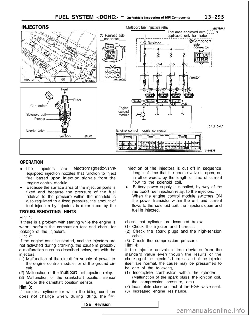
OPERATION
l The injectorsare electromagnetic-valve-
equipped injection nozzles that function to inject
fuel based upon injection signals from the engine control module.
lBecause the surface area of the injection ports is
fixed and because the pressure of the fuel relative to the pressure within the manifold is
also regulated to a fixed pressure, the amount of
fuel injection by injectors is determined by the
TROUBLESHOOTING HINTS
Hint 1:
If there is a problem with starting while the engine is
warm, perform the combustion test and check for leakage of the injectors.Hint 2:
If the engine can’t be started, and the injectors are
not activated during cranking, the cause is probably
a malfunction such as described below, not with the injectors.
(1) Malfunction of the circuit for supply of power to
the engine control module, or of the ground cir-
cuit.
(2) Malfunction of the multiport fuel injection relay.
(3) Malfunction of the crankshaft position sensor and/or the camshaft position sensor.
Hint 3:
If there is a cylinder for which the idling condition
does not change when, during idling, the fuelinjection of the injectors is cut off in sequence,
length of time that the needle valve is open, or,
in other words, by the length of time of current
flow to the solenoid coil.
lBattery power supply is supplied, by way of the
multiport fuel injection relay, to the injectors.
When the engine control module switches ON
the power transistor within the unit and current
flows to the solenoid coil, the injectors open and
fuel is injected.
check that cylinder as described below.
(1) Check the injector and harness.
(2) Check the spark plugs and the high-tension
cable.
(3) Check the compression pressure. Hint 4:
if the injector activation time deviates from the
standard value even though the results of the
checking of the injector’s harness and of the injector
itself are normal, the cause may be pressumed to
be one of the following,
(1) Incomplete combustion within the cylinder.
(Malfunction of the spark plugs, the ignition coil,
the compression pressure, etc.)
(2) Incomplete close contact of the EGR valve seat.
(3) Increased engine resistance.
TSB Revision
Page 1040 of 1273
ACTIVE-ELECTRONIC CONTROL SUSPENSION - Strut Assembly33B-101
12AO275
12LO254
Strut insulator bearing12LOO34
12LO254
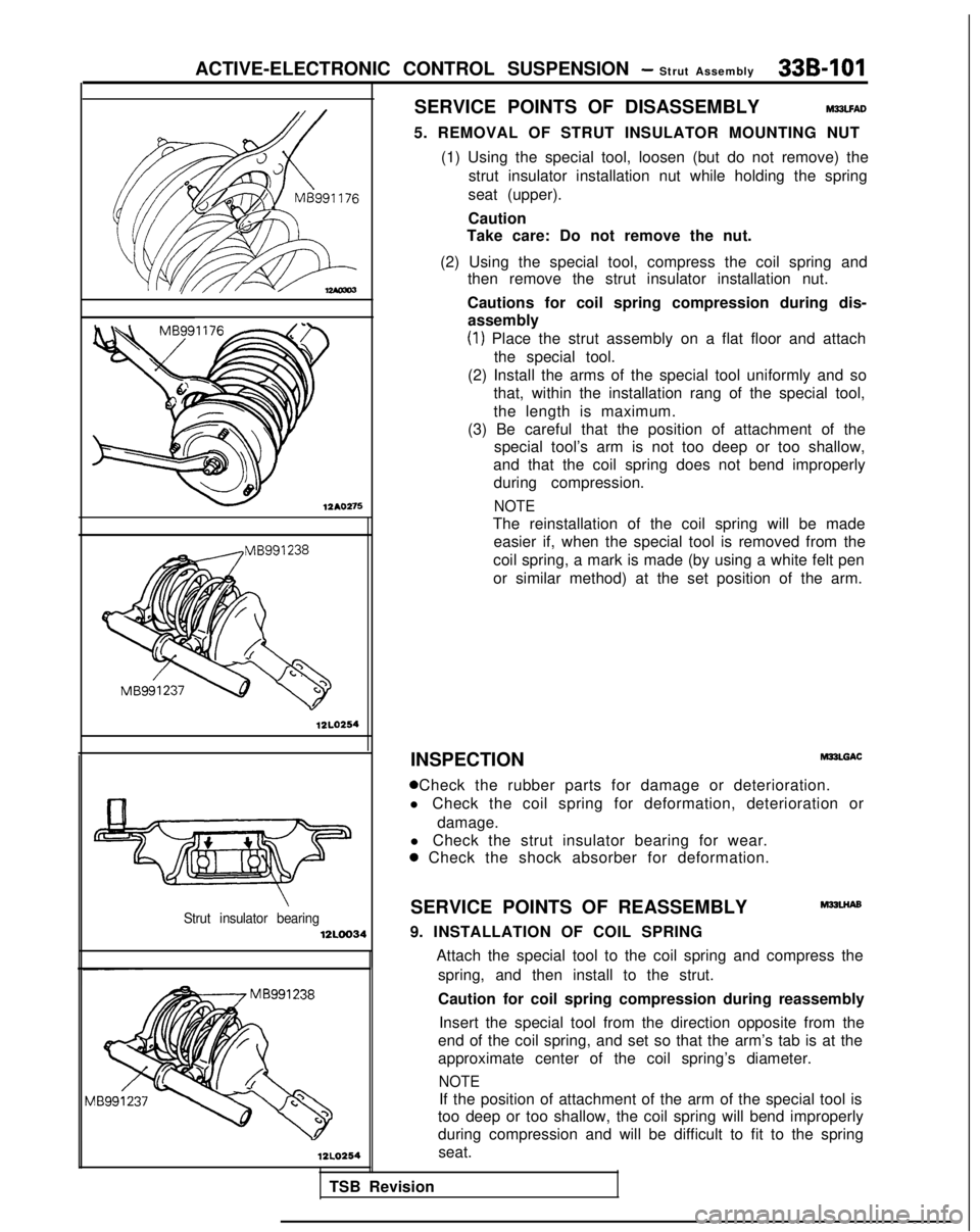
SERVICE POINTS OF DISASSEMBLYM23LFAD
5. REMOVAL OF STRUT INSULATOR MOUNTING NUT
(1) Using the special tool, loosen (but do not remove) the strut insulator installation nut while holding the spring
seat (upper).
Caution
Take care: Do not remove the nut.
(2) Using the special tool, compress the coil spring and then remove the strut insulator installation nut.
Cautions for coil spring compression during dis- assembly
(1) Place the strut assembly on a flat floor and attach
the special tool.
(2) Install the arms of the special tool uniformly and so that, within the installation rang of the special tool,
the length is maximum.
(3) Be careful that the position of attachment of the special tool’s arm is not too deep or too shallow,
and that the coil spring does not bend improperly during compression.
NOTE
The reinstallation of the coil spring will be made easier if, when the special tool is removed from the
coil spring, a mark is made (by using a white felt pen
or similar method) at the set position of the arm.
INSPECTION MPLGAC
0 Check the rubber parts for damage or deterioration.
l Check the coil spring for deformation, deterioration or
damage.
l Check the strut insulator bearing for wear.
a Check the shock absorber for deformation.
SERVICE POINTS OF REASSEMBLY
M32LHAs
9. INSTALLATION OF COIL SPRING
TSB Revision Attach the special tool to the coil spring and compress the
spring, and then install to the strut.
Caution for coil spring compression during reassembly
Insert the special tool from the direction opposite from the
end of the coil spring, and set so that the arm’s tab is at the
approximate center of the coil spring’s diameter.
NOTE
If the position of attachment of the arm of the special tool is
too deep or too shallow, the coil spring will bend improperly
during compression and will be difficult to fit to the spring
seat.
Page 1123 of 1273
35-2
SERVICE BRAKES - Specifications
SPECIFICATIONS
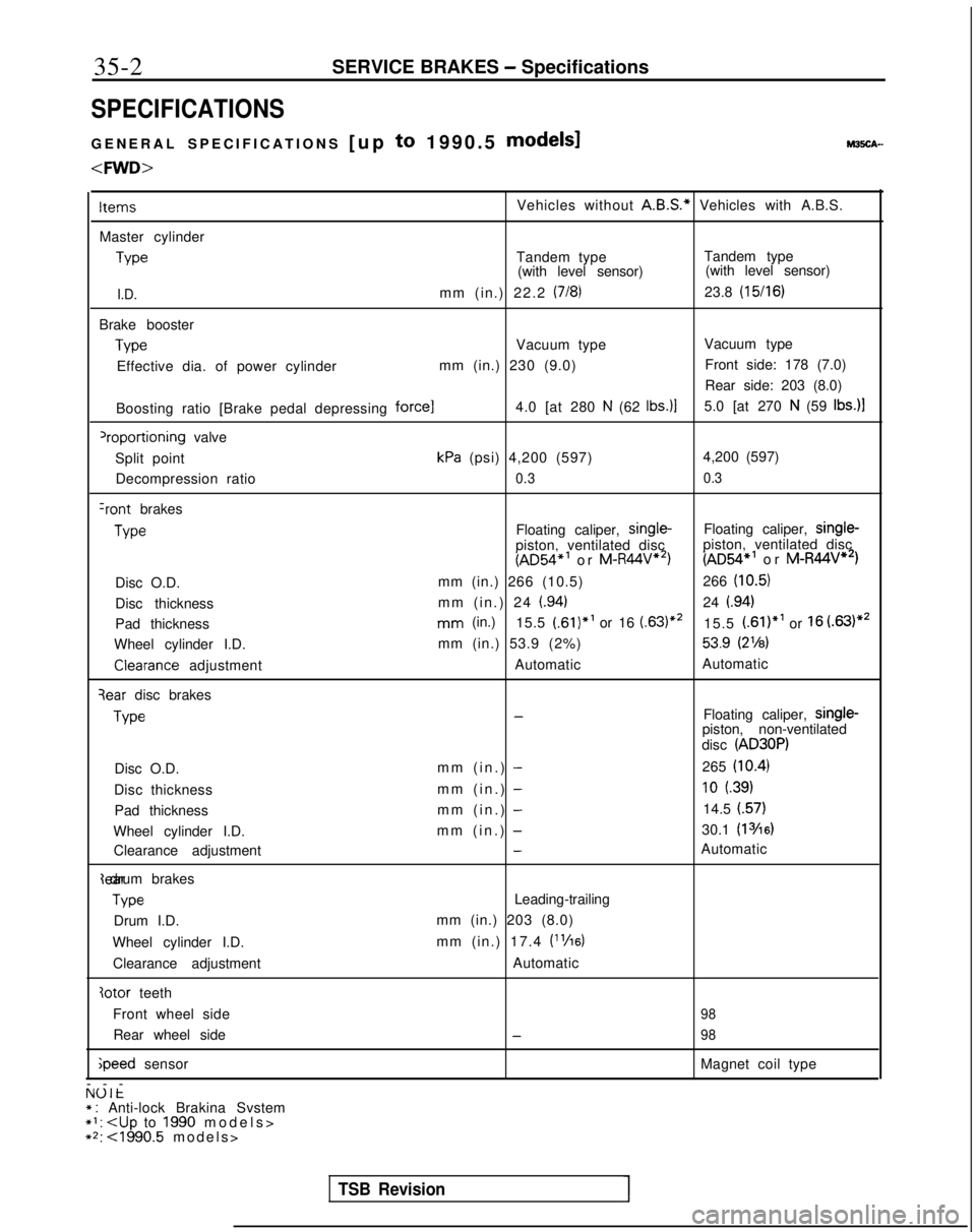
GENERAL SPECIFICATIONS
[up to 1990.5 models1 M3!iCA-
ItemsVehicles without
A.B.S.*
Vehicles with A.B.S.
Master cylinder Type
Tandem type
Tandem type
(with level sensor) (with level sensor)
I.D.mm (in.) 22.2 (718)23.8 (15/16)
Brake boosterType
Vacuum type
Vacuum type
Effective dia. of power cylinder mm (in.) 230 (9.0)Front side: 178 (7.0)
Rear side: 203 (8.0)
Boosting ratio [Brake pedal depressing
force14.0 [at 280 N (62 tbs.)]5.0 [at 270 N (59 Ibs.)l
‘roportioning valve
Split point
kPa (psi) 4,200 (597) 4,200 (597)
Decompression ratio
0.3 0.3
Iront brakesType
Floating caliper, single-
Floating caliper, single-
piston, ventilated disc
(AD54*’ or M-R44V”‘)piston, ventilated disc (AD54*’
or M-R44V**)
Disc O.D. mm (in.) 266 (10.5)
266
(10.5)
Disc thickness mm (in.) 24 (.94)24 i.94)
Pad thicknessmm (in.)
15.5 (.61)*’ or 16 (63)“’15.5 (.61)*’ or 16 (.63)**
Wheel cylinder I.D. mm (in.) 53.9 (2%)
53.9 (2’/8)Clearance
adjustment AutomaticAutomatic
qear disc brakesType
-Floating caliper, single-
piston, non-ventilated
disc
(AD30P)
Disc O.D. mm (in.) -265 (10.4)
Disc thickness
mm (in.) -10 (.39)
Pad thicknessmm (in.) -14.5 (.57)
Wheel cylinder I.D. mm (in.) -30.1 (13/16)
Clearance adjustment-Automatic{ear drum brakes
Type
Leading-trailing
Drum I.D. mm (in.) 203 (8.0)
Wheel cylinder I.D. mm (in.) 17.4
V’/16)
Clearance adjustment
Automatic
Iotor teeth
Front wheel side
98
Rear wheel side-98 ;peed
sensor Magnet coil type
---
NUlt* : Anti-lock Brakina Svstem*I:
+2: ~1990.5 models
>
TSB RevisionI