Page 178 of 1273
13-36 FUEL SYSTEM - Service Adjustment Procedures
:I989 models>
M
D9684783FUO179
models> Sensor side connector
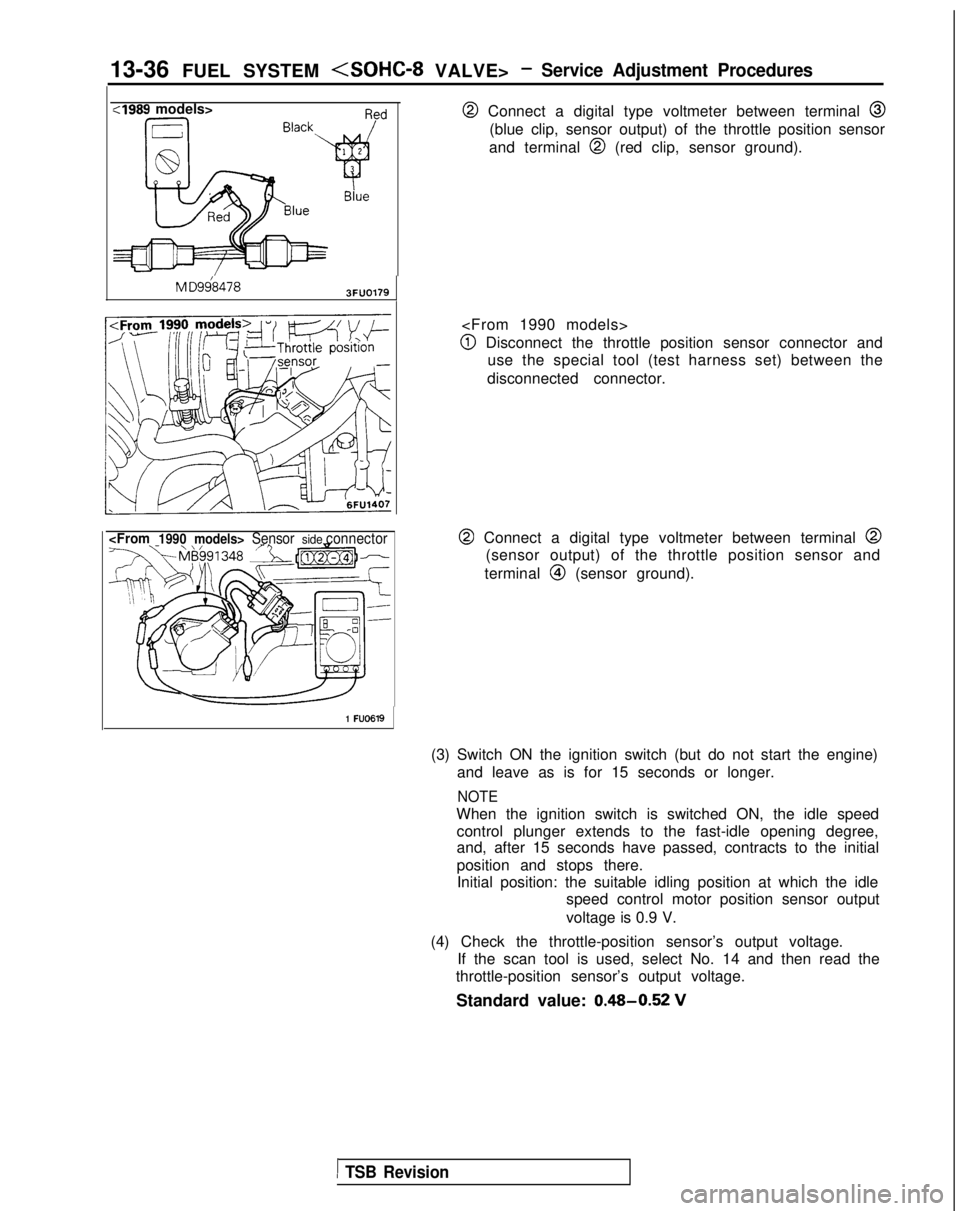
@ Connect a digital type voltmeter between terminal @
(blue clip, sensor output) of the throttle position sensor
and terminal
@I (red clip, sensor ground).
@I Disconnect the throttle position sensor connector and use the special tool (test harness set) between the
disconnected connector.
@ Connect a digital type voltmeter between terminal @
(sensor output) of the throttle position sensor and
terminal
@I (sensor ground).
1 FU0619
(3) Switch ON the ignition switch (but do not start the engine) and leave as is for 15 seconds or longer.
NOTE
When the ignition switch is switched ON, the idle speedcontrol plunger extends to the fast-idle opening degree,
and, after 15 seconds have passed, contracts to the initial
position and stops there.Initial position: the suitable idling position at which the idle speed control motor position sensor output
voltage is 0.9 V.
(4) Check the throttle-position sensor’s output voltage. If the scan tool is used, select No. 14 and then read the
throttle-position sensor’s output voltage.
Standard value: 0.48-0.52
V
1 TSB Revision
Page 179 of 1273
FUEL SYSTEM (SOHC-8 VALVE> -Service Adjustment Procedures 13-37
--
MO-L
6FU1405
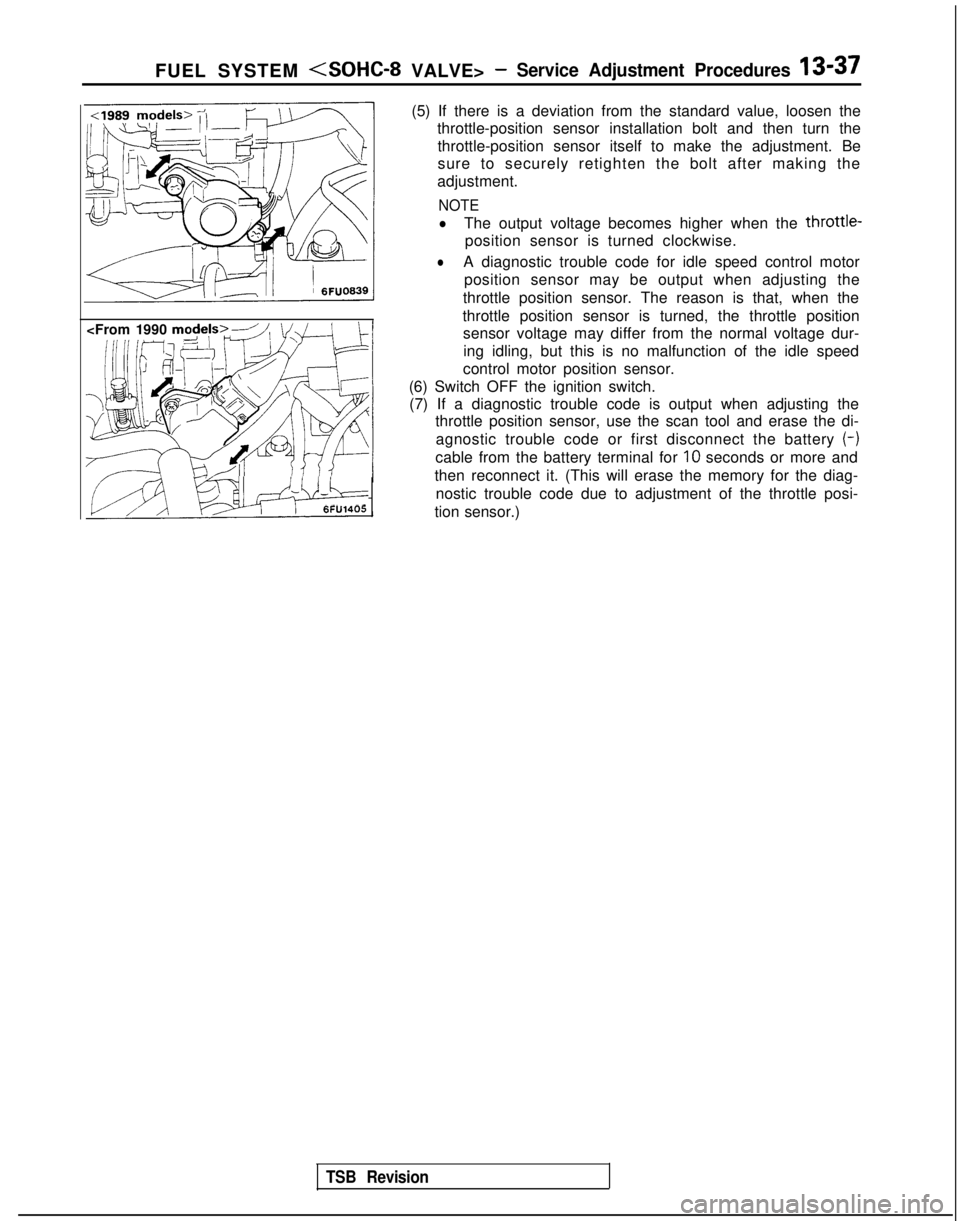
(5) If there is a deviation from the standard value, loosen the
throttle-position sensor installation bolt and then turn the
throttle-position sensor itself to make the adjustment. Be
sure to securely retighten the bolt after making the
adjustment.
NOTE
lThe output voltage becomes higher when the throttle-
position sensor is turned clockwise.
lA diagnostic trouble code for idle speed control motor position sensor may be output when adjusting the
throttle position sensor. The reason is that, when the
throttle position sensor is turned, the throttle position sensor voltage may differ from the normal voltage dur-
ing idling, but this is no malfunction of the idle speed
control motor position sensor.
(6) Switch OFF the ignition switch. (7) If a diagnostic trouble code is output when adjusting the throttle position sensor, use the scan tool and erase the di-
agnostic trouble code or first disconnect the battery (-)
cable from the battery terminal for IO
seconds or more and
then reconnect it. (This will erase the memory for the diag- nostic trouble code due to adjustment of the throttle posi-
tion sensor.)
TSB Revision
Page 180 of 1273
Page 181 of 1273
FUEL SYSTEM - On-Vehicule Inspection of MFI Components13-39
Oxygen sensor
n
1<19& &odekw
sensor
,,< \;F”O85:
:Frory zy models>7-motor (closed
throttle sition
switch and
or
Dositionsensor)
1;’Y/\l IV/A 6FU;4061
1\
6FUO8571\ \I / /
TSB Revision
Page 184 of 1273
13-42 FUEL SYSTEM - On-Vehicule Inspection of MFI Components
(9) Switch OFF the ignition switch. (10)Disconnect
the scan tool. (11)Restart
the engine and perform a driving test, etc. to
confirm that the malfunction has been corrected.
POWER SUPPLY
Engine
control moduleu\\ v
OPERATION
l While the ignition switch is ON, battery power
supply is supplied to the engine control module,injectors, volume air flow sensor, etc.
l When the ignition switch is switched ON, cur-
rent flows from the ignition switch, via the MFI
relay coil to ground.
INSEPCTION
Using Scan Tool
relay ’
\/\/\/“
2
“3 “6
CL I 4,
Harness
side connector
Engine control module connector OlLO838
As a result, the MFI relay switch is switched ON,
and power is supplied, by way of the
MFI relay
switch, from the battery to the engine control
module.
IFunctionData displayICheck conditionsIStandard valueI
Data reading16Engine control modulepower-supply voltageIgnition switch: ONBattery positive voltage
1 TSB Revision
Page 191 of 1273
FUEL SYSTEM -On-Vehicule Inspection of MFI Components13-49
VOLUME AIR FLOW SENSOR
@ ;;vonent
connector
Intake air amount
(Wsec)162451
Multipoh fuel
injection relay
Volume air flow sensor
/\2/\N
Harness side
connector
IHjhcillo)
1.10
f-i5V
Engine
control
module
MlOYFAA
J 6FU1394
OPERATION
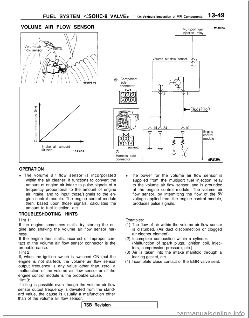
l The volume air flow sensor is incorporated
within the air cleaner; it functions to convert the
amount of engine air intake to pulse signals of a
frequency proportional to the amount of engine air intake, and to input those/signals to the en-
gine control module. The engine control module
then, based upon those signals, calculates the amount to fuel injection, etc.
TROUBLESHOOTING HINTS
Hint 1:
If the engine sometimes stalls, try starting the en-
gine and shaking the volume air flow sensor har-
ness.
If the engine then stalls, incorrect or improper con-
tact of the volume air flow sensor connector is the probable cause.
Hint 2:
If, when the ignition switch is switched ON (but the
engine is not started), the volume air flow sensor
output frequency is any value other than zero, a
malfunction of the volume air flow sensor or of the
engine control module is the probable cause. Hint 3:
If idling is possible even though the volume air flow
sensor output frequency is deviated from the stand-
ard value, the cause is usually a malfunction other
than of the volume air flow sensor. l The power for the volume air flow sensor is
supplied from the multiport fuel injection relay
to the volume air flow sensor, and is grounded at the engine control module. The volume air
flow sensor, by intermitting the flow of the
5V
voltage applied from the engine control module,
produces pulse signals.
Examples:
(1) The flow of air within the volume air flow sensor is disturbed. (Air duct disconnection or clogged
air cleaner element)
(2) Incomplete combustion within a cylinder. (Malfunction of spark plugs, ignition coil, injec-
tors, compression pressure, etc.)
(3) Air is taken into the intake manifold through a leaking gasket, etc.
(4) Incomplete close contact of the EGR valve seat.
TSB Revision
Page 192 of 1273
13-50 FUEL SYSTEM - On-Vehicule Inspection of MFI Components
INSPECTION
Using Scan Tool
Item No. Data display Inspection conditions
12Sensor de-
tection air
volume (fre-
quency) . Engine coolant
temperature: 85-95°C(185-205°F). Lights, cooling fan, elec-
trical accessories: OFF
. Transaxle: neutral (iVT
models: “P” range)
RacingFrequency in-
creases as racing
rpm increases.
NOTEThe volume air flow sensor output frequency may be about 10% higher than\
indicated above when the vehicle is new [driven approximately 500 km (300 miles) or less].
Regular waveform 03A0203
HARNESS INSPECTION
@
Harness sideconnector
6
0-0
~
0
=
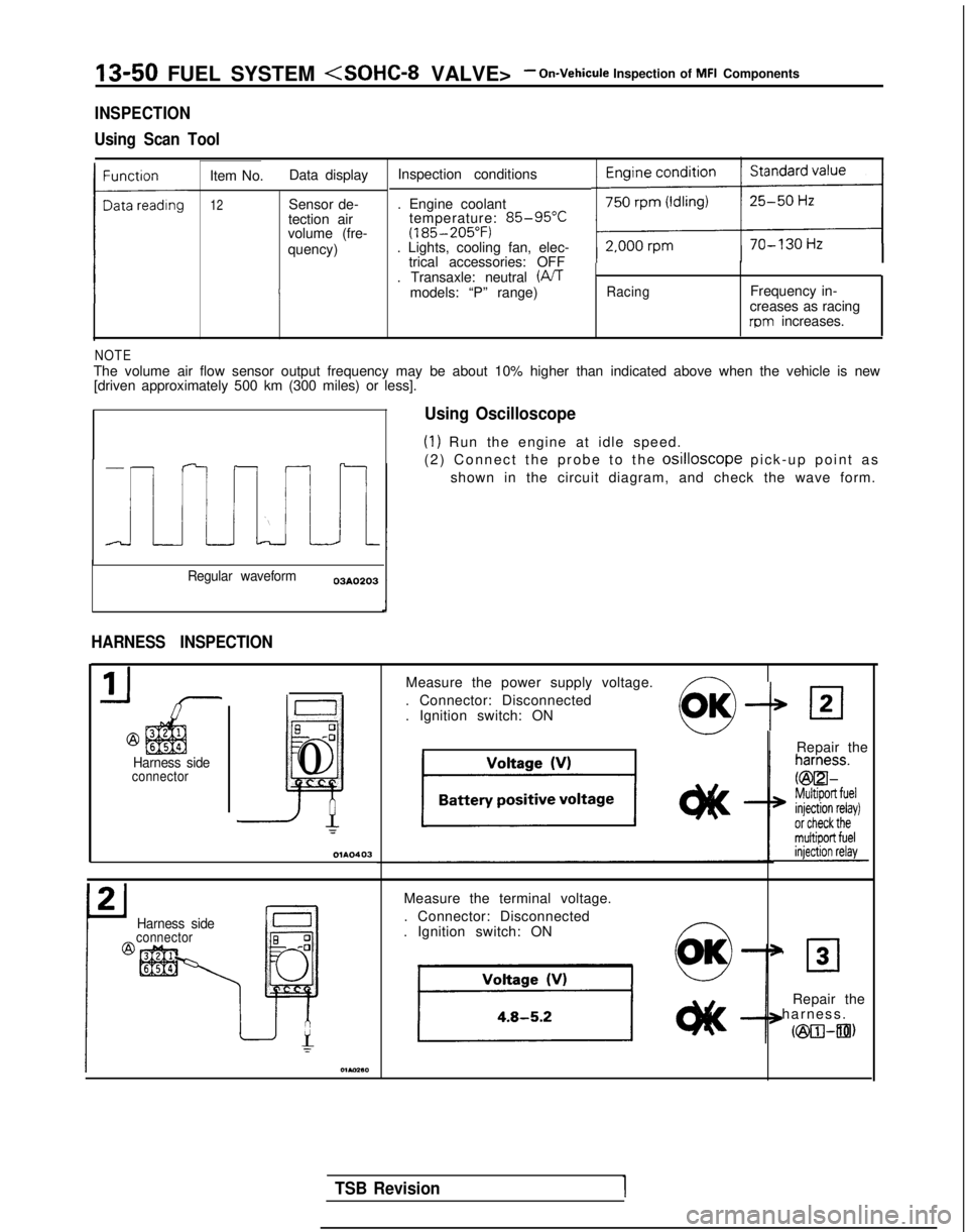
Using Oscilloscope
(1) Run the engine at idle speed.
(2) Connect the probe to the
osilloscope pick-up point a
s
shown in the circuit diagram, and check the wave form.
Measure the power supply voltage.
. Connector: Disconnected
. Ignition switch: ON
--P
IRepair the
Harness sideconnector
Measure the terminal voltage.
. Connector: Disconnected
. Ignition switch: ON ~
0
OK’ 30
Repair the
harness
.
cm-an)
TSB Revision1
Page 193 of 1273
FUEL SYSTEM
VALVE> - On-Vehicule Inspection of MFI ComponentsI%51
Harness side
Check for continuity of the ground
circuit.
. Connector: Disconnected
@+A
Repair the
harness.
@3l-FiBill
J
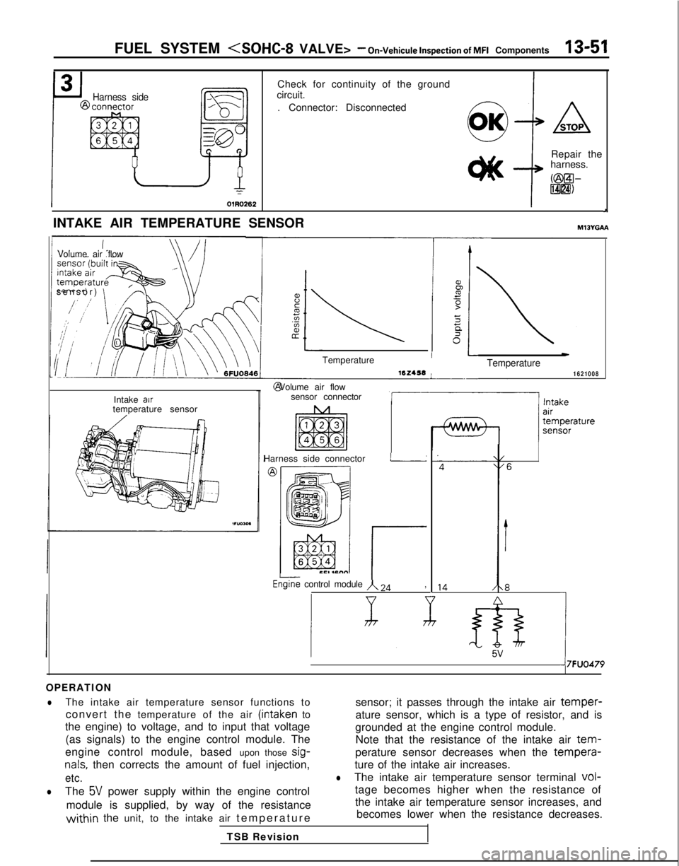
INTAKE AIR TEMPERATURE SENSORMlJYGAA
Volume air flow
sensor)
\
Intake air
temperature sensor Temperature 16Z456
L- @ Volume air flow
sensor connector
Harness side connector
I
rEGine control module A 24,
wTemperature1621008
&5V1
7FUO479
OPERATION
lThe intake air temperature sensor functions to sensor; it passes through the intake air temper-
convert the temperature of the air (intaken to
ature sensor, which is a type of resistor, and is
the engine) to voltage, and to input that voltage grounded at the engine control module.
(as signals) to the engine control module. The Note that the resistance of the intake air
tem-
engine control module, based upon those sig-perature sensor decreases when the tempera-
nals, then corrects the amount of fuel injection,
ture of the intake air increases.
etc.lThe intake air temperature sensor terminal vol-
lThe 5V power supply within the engine control
tage becomes higher when the resistance of
module is supplied, by way of the resistance the intake air temperature sensor increases, and
within the unit, to the intake air
temperatur
e
becomes lower when the resistance decreases.
TSB Revision