1989 MITSUBISHI GALANT sensor
[x] Cancel search: sensorPage 265 of 1273
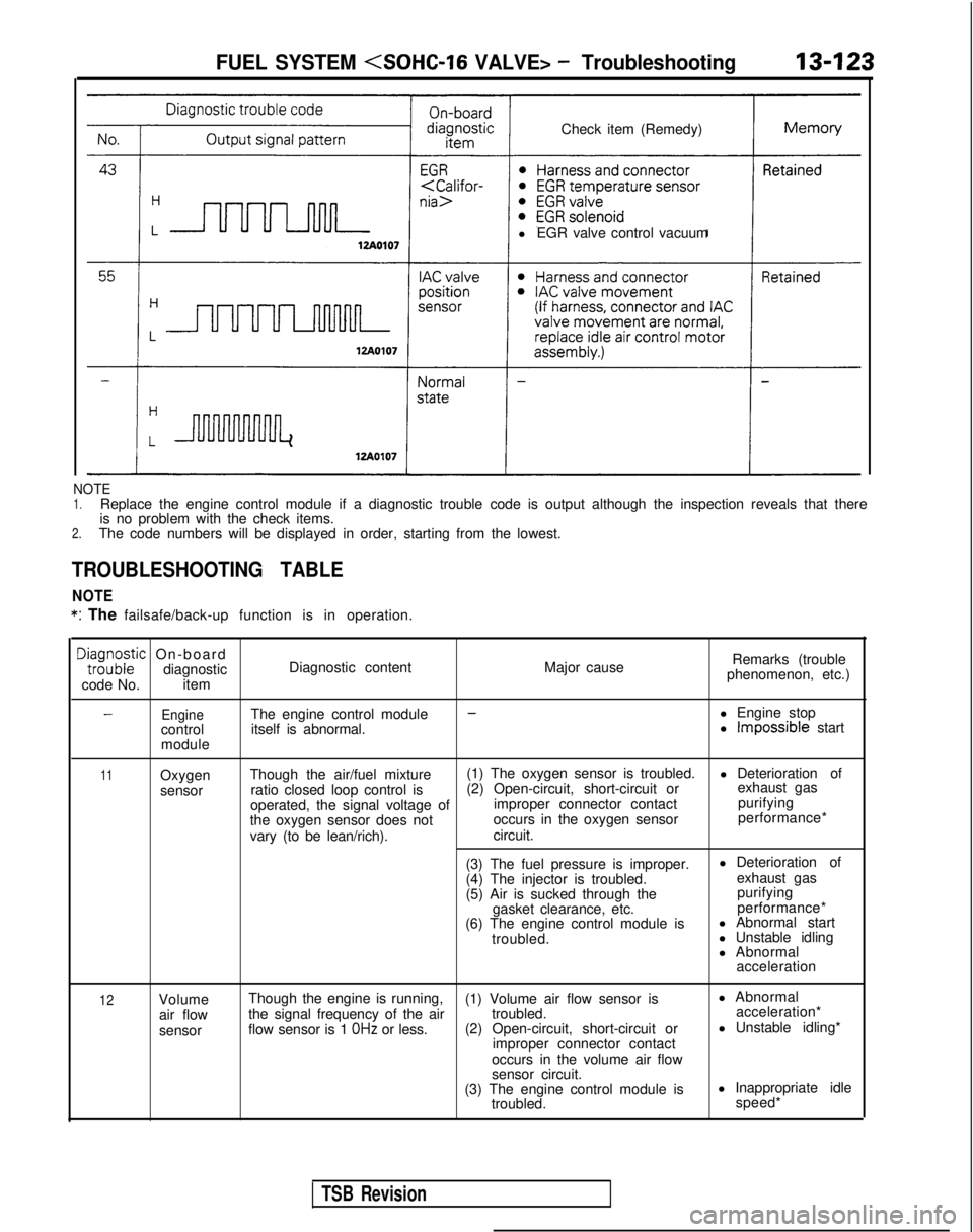
Check item (Remedy)
l EGR valve control vacuumFUEL SYSTEM
NOTE1.Replace the engine control module if a diagnostic trouble code is output\
although the inspection reveals that there
is no problem with the check items.
2.The code numbers will be displayed in order, starting from the lowest.
TROUBLESHOOTING TABLE
NOTE *:
The failsafe/back-up function is in operation.
DE;;;zic On-board
diagnostic
code No. item Diagnostic content
Major causeRemarks (trouble
phenomenon, etc.)
EngineThe engine control module--l Engine stop
control itself is abnormal. l Impossible start
module
11Oxygen
sensor Though the air/fuel mixture
(1) The oxygen sensor is troubled.
l Deterioration of
ratio closed loop control is (2) Open-circuit, short-circuit or exhaust gas
operated, the signal voltage of improper connector contact purifying
the oxygen sensor does not occurs in the oxygen sensor performance*
vary (to be lean/rich). circuit.
(3) The fuel pressure is improper. l Deterioration of
(4) The injector is troubled. exhaust gas
(5) Air is sucked through the purifying
gasket clearance, etc. performance*
(6) The engine control module is l Abnormal start
troubled. l Unstable idling
l Abnormal
acceleration
12Volume
air flow
sensor Though the engine is running,
(1) Volume air flow sensor is l Abnormal
the signal frequency of the air troubled. acceleration*
flow sensor is 1
OHz or less. (2) Open-circuit, short-circuit or l Unstable idling*
improper connector contact
occurs in the volume air flow
sensor circuit.
(3) The engine control module is l Inappropriate idle
troubled. speed*
TSB Revision
Page 266 of 1273
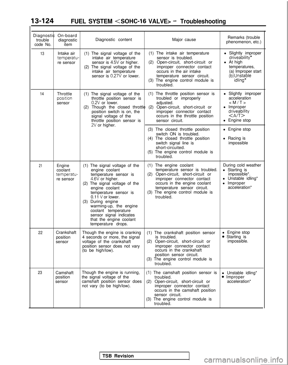
13-124FUEL SYSTEM
Diagnostic On-board
trouble diagnostic
code No.item Diagnostic content
Major causeRemarks (trouble
phenomenon, etc.)
13
14Intake air (1) The signal voltage of the (1) The intake air temperature
l Slightly impropertemperatu-intake air temperature
sensor is troubled.driveability*
re sensorsensor is 4.5V or higher.(2) Open-circuit, short-circuit or
l At high
(2) The signal voltage of the improper connector contacttemperatures,
intake air temperature occurs in the air intake (a) Improper start
sensor is
0.27V or lower. temperature sensor circuit.
(3) The engine control module isiWJ;sn$aple
troubled.
Throttle (1) The signal voltage of the (1) The throttle position sensor is
l Slightly improperposltion
throttle position sensor is troubled or improperly acceleration
sensor
0.2V or lower. adjusted.
(2) Though the closed throttle (2) Open-circuit, short-circuit or l Improper
position switch is on, the improper connector contact
signal voltage of the occurs in the throttle position
d&eTbQ
throttle position sensor is
sensor circuit. l Engine stop2V or higher.
(3) The closed throttle position l Engine stop
switch ON is troubled.
(4) The closed throttle position l Racing is
switch signal line is impossible
short-circuited.
(5) The engine control module is
troubled.
21Engine(1) The signal voltage of the (1) The engine coolant
During cold weather
coolant engine coolant temperature sensor is troubled.
l Starting is
temperatu-temperature sensor is(2) Open-circuit, short-circuit or
impossible*.
re sensor4.6V or higher. improper connector contact l Unstable idling*
(2) The signal voltage of the occurs in the engine coolant
l Improper
engine coolant temperature sensor circuit. acceleration*
temperature sensor is (3) The engine control module is
0.11
V or lower. troubled.
(3) During engine warming-up, the engine
coolant temperature
sensor signal indicates
that the engine coolant
temperature drops.
22Crankshaft Though the engine is cranking (1) The crankshaft position sensor l Engine stop
position 4 seconds or more, the signal is troubled.0 Starting is
sensor voltage of the crankshaft (2) Open-circuit, short-circuit or impossible.
position sensor does not vary improper connector contact
(to be high/low). occurs in the crankshaft
position sensor circuit.
(3) The engine control module is
troubled.
23Camshaft Though the engine is running,(1) The camshaft position sensor is
l Unstable idling*
position the signal voltage of the
troubled.0 Improper
sensor camshaft position sensor does
(2) Open-circuit, short-circuit or acceleration*
not vary (to be high/low). improper connector contact
occurs in the camshaft position
sensor circuit.
(3) The engine control module is
troubled.
TSB Revision
Page 267 of 1273
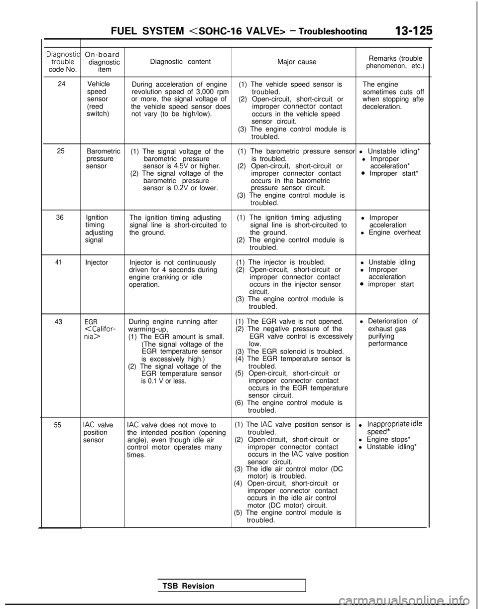
FUEL SYSTEM
Dta,i;o;ic On-board
diagnostic
code No. item Diagnostic content
Major causeRemarks (trouble
phenomenon, etc.)
24
Vehicle
speed
sensor
(reed
switch) During acceleration of engine
(1) The vehicle speed sensor is The engine
revolution speed of 3,000 rpm troubled.sometimes cuts off
or more, the signal voltage of (2) Open-circuit, short-circuit or when stopping afte
the vehicle speed sensor does improper connector
contact
deceleration.
not vary (to be high/low). occurs in the vehicle speed
sensor circuit.
(3) The engine control module is troubled.
25Barometric (1) The signal voltage of the (1) The barometric pressure sensor l Unstable idling*
pressure barometric pressure is troubled. l Improper
sensor sensor is
4.5V or higher.(2) Open-circuit, short-circuit or acceleration*
(2) The signal voltage of the improper connector contact0 Improper start*
barometric pressure occurs in the barometric
sensor is
0.2V or lower. pressure sensor circuit.
(3) The engine control module is troubled.
36Ignition
timing
adjusting
signal The ignition timing adjusting
(1) The ignition timing adjusting
l Improper
signal line is short-circuited to signal line is short-circuited toacceleration
the ground. the ground.l Engine overheat
(2) The engine control module is troubled.
41Injector Injector is not continuously
driven for 4 seconds during
engine cranking or idle
operation. (1) The injector is troubled.
(2) Open-circuit, short-circuit or improper connector contact
occurs in the injector sensor
circuit. l Unstable idling
l Improper acceleration
0 improper start
(3) The engine control module is troubled.
43EGRDuring engine running after (1) The EGR valve is not opened. l Deterioration of
purifying
(The signal voltage of the low. performance
EGR temperature sensor (3) The EGR solenoid is troubled.
is excessively high.) (4) The EGR temperature sensor is
(2) The signal voltage of the troubled.
EGR temperature sensor (5) Open-circuit, short-circuit or
is 0.1 V or less.improper connector contact
occurs in the EGR temperature
sensor circuit.
(6) The engine control module is
troubled.
55IAC valveIAC valve does not move to (1) The IAC valve position sensor is
position the intended position (opening troubled.l ;papp$Priate idle
sensor angle), even though idle air (2) Open-circuit, short-circuit or
l Engine stops*
control motor operates many improper connector contactl Unstable idling*
times. occurs in the
IAC valve position
sensor circuit.
(3) The idle air control motor (DC
motor) is troubled.
(4) Open-circuit, short-circuit or
improper connector contact
occurs in the idle air control
motor (DC motor) circuit.
(5) The engine control module is
troubled.
TSB Revision
Page 268 of 1273
13-126FUEL SYSTEM
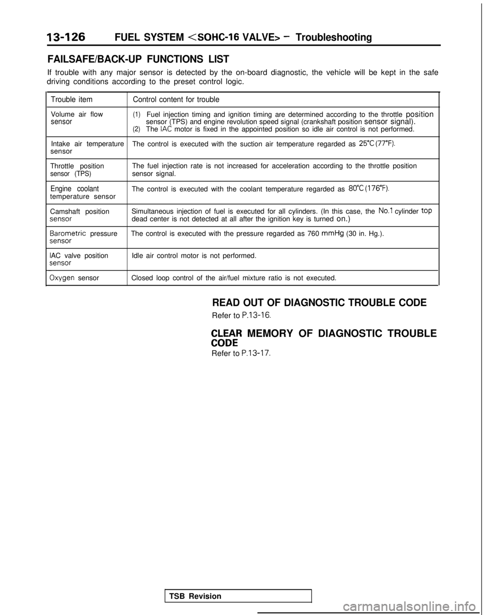
FAILSAFE/BACK-UP FUNCTIONS LIST
If trouble with any major sensor is detected by the on-board diagnostic,\
the vehicle will be kept in the safe
driving conditions according to the preset control logic.
Trouble item Control content for trouble
Volume air flow(1)Fuel injection timing and ignition timing are determined according to th\
e throttle positionsensorsensor (TPS) and engine revolution speed signal (crankshaft position \
sensor signal).(2)The IAC motor is fixed in the appointed position so idle air control is not per\
formed.
Intake air temperature The control is executed with the suction air temperature regarded as
25°C (77°F).sensor
Throttle position The fuel injection rate is not increased for acceleration according to t\
he throttle position
sensor (TPS)sensor signal.
Engine coolantThe control is executed with the coolant temperature regarded as 80°C (176’F).temperature sensor
Camshaft positionSimultaneous injection of fuel is executed for all cylinders. (In this \
case, the
No.1 cylinder top
jenS0r
dead center is not detected at all after the ignition key is turned
on.)3arometric
pressure The control is executed with the pressure regarded as 760 mmHg
(30 in. Hg.).
sensor
AC valve position Idle air control motor is not performed.;ensor
Ixygen sensor
Closed loop control of the air/fuel mixture ratio is not executed.
READ OUT OF DIAGNOSTIC TROUBLE CODE
Refer to P.13-16.
EbW&R MEMORY OF DIAGNOSTIC TROUBLE
Refer to
P.13-17.
TSB Revision
Page 269 of 1273
FUEL SYSTEM
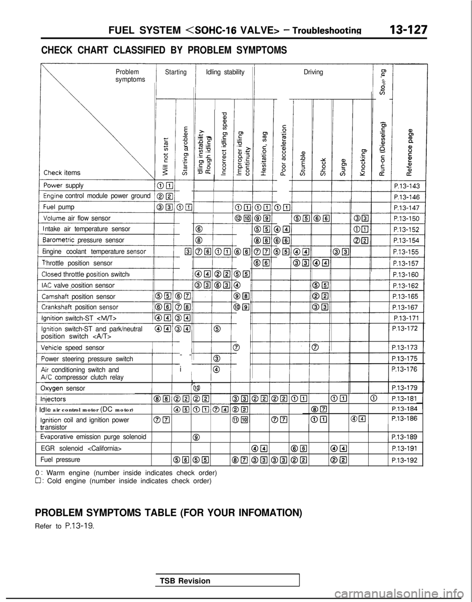
CHECK CHART CLASSIFIED BY PROBLEM SYMPTOMS
ProblemsymptomsStartingIdling stability Drivingr”
.-
%scn
E5
$4.a,o_
5;i
cz
iP.13-143
-
Ea,Ll2a
F.- s
G-
DE-
c-
Elc
-
-
>El
)El-
)I3-
)@I
I-
-
i
-
5‘32a,$%ba”
D&l DEI
i>El
-0%,a>+y -2.gPE.-50 z.E r2?p9 6=& g-
-
-Sheck items
‘ower
supply
%ginecontrol module power groundI
1 P.13-146
:uel pump
Jolume air flow sensor
B
f
E3
DELI @El
cP.13-162
P.13-165III P.13-167I
1/ P.l3-171 1
P.l3-172
P.l3-173
P.l3-175
P.13-176
P.l3-179
ntake air temperature sensor
BIB
DEI
0
DEl
3El
3
-I
iarometric
pressure sensor
ingine coolant temperature
sensor
‘hrottle position sensor
Iosed throttlepositionswitch
K valve oosition sensor
lamshaft position sensor
i-:rankshaft positionsensorIIlnition
switch-ST
-I---0lnition switch-ST and park/neutralosition switch
chicle
speed sensor
ower steering pressure switch
ir conditioning switch and/C compressor clutch relayI/I- IIlxygen sensor
@El@ P.l3-181
@ElP.13-184
@[email protected]
Ile air control motor (DC motor)
inition coil and ignition powerOFI@piJOEIansistor
tiaporative emission purge solenoid01 P.13-189
1 Id
kl
c
tr
t
EGR solenoid
Fuel pressureOIlI @El8E.l @El @El @[email protected]
0 : Warm engine (number inside indicates check order)
0 : Cold engine (number inside indicates check order)
PROBLEM SYMPTOMS TABLE (FOR YOUR INFOMATION)
Refer to P.13-19.
TSB Revision
Page 278 of 1273
13-136FUEL SYSTEM
TPS connector
7FUO629
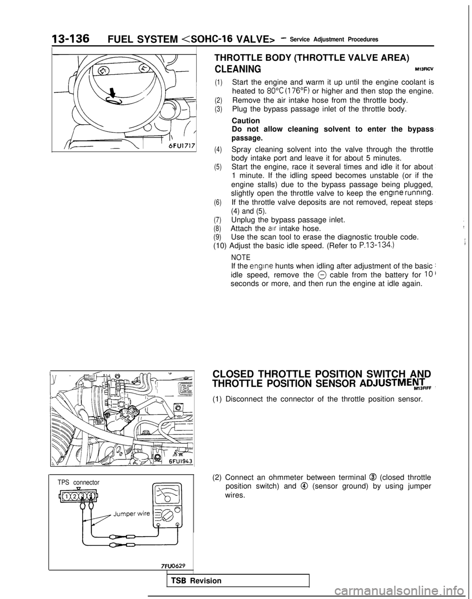
THROTTLE BODY (THROTTLE VALVE AREA)
CLEANINGMl3Rcv
(1)Start the engine and warm it up until the engine coolant is
heated to
80°C (176°F) or higher and then stop the engine.
(2)Remove the air intake hose from the throttle body.
(3)Plug the bypass passage inlet of the throttle body.
Caution
Do not allow cleaning solvent to enter the bypass
passage.
(4)Spray cleaning solvent into the valve through the throttle
body intake port and leave it for about 5 minutes.
(5)Start the engine, race it several times and idle it for about 1 minute. If the idling speed becomes unstable (or if the
engine stalls) due to the bypass passage being plugged,
slightly open the throttle valve to keep the engine
running.
(6)If the throttle valve deposits are not removed, repeat steps
(4) and (5).
(7)Unplug the bypass passage inlet.
(8)Attach the air intake hose.
(9)Use the scan tool to erase the diagnostic trouble code.
(10) Adjust the basic idle speed. (Refer to
P.13-134.)
NOTE
If the engrne hunts when idling after adjustment of the basic
idle speed, remove the
@ cable from the battery for 10
seconds or more, and then run the engine at idle again.
CLOSED THROTTLE POSITION SWITCH AND
THROTTLE POSITION SENSOR ADJUSTMEy,zIFF
(1) Disconnect the connector of the throttle position sensor.
(2) Connect an ohmmeter between terminal
@I (closed throttle
position switch) and
@ (sensor ground) by using jumper
wires.
TSB Revision
Page 279 of 1273
FUEL SYSTEM
I;gFixed SAS
Terminal @Terminal @(sensor output) (sensor ground) /
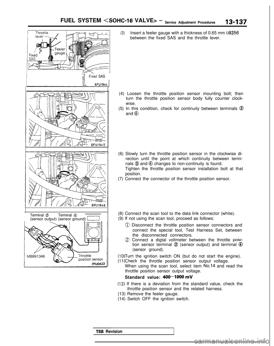
(3)Insert a feeler gauge with a thickness of 0.65 mm (.0256 in.)
between the fixed SAS and the throttle lever.
(4) Loosen the throttle position sensor mounting bolt; then turn the throttle position sensor body fully counter clock-
wise.
(5) In this condition, check for continuity between terminals
@
and 0.
(6) Slowly turn the throttle position sensor in the clockwise di- rection until the point at which continuity between termi-
nals
@I and @ changes to non-continuity is found.
Tighten the throttle position sensor installation bolt at that position.
(7) Connect the connector of the throttle position sensor.
(8) Connect the scan tool to the data link connector (white).
(9) If not using the scan tool, proceed as follows:
0 Disconnect the throttle position sensor connectors and connect the special tool, Test Harness Set, between
the disconnected connectors.
0 Connect a digtal voltmeter between the throttle posi-
tion sensor terminal
@ (sensor output) and terminal Q
(sensor ground).
(lO)Turn the ignition switch ON (but do not start the engine).
(11)Check the throttle position sensor output voltage.
When using the scan tool, select item
No.14 and read the
throttle position sensor output voltage.
Standard value:
400-1000 mV
(12) If there is a deviation from the standard value, check the throttle position sensor and the related harness.
(13) Remove the feeler gauge.
(14) Switch OFF the ignition switch.
TSB Revision
Page 280 of 1273
13-138
FUEL SYSTEM (SOHC-16 VALVE>- Service Adjustment Procedures
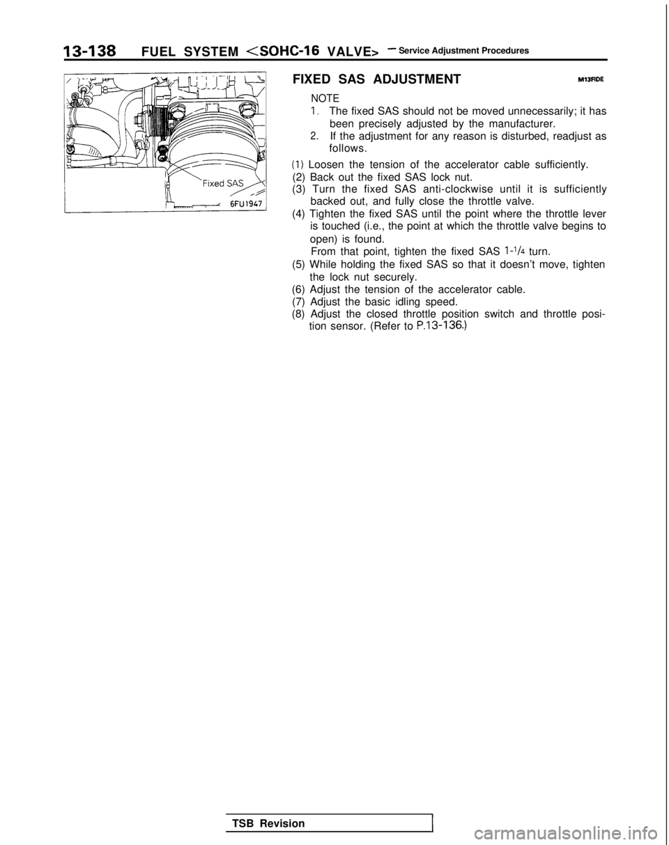
FIXED SAS ADJUSTMENT
M13FlDE
NOTE
I,The fixed SAS should not be moved unnecessarily; it has been precisely adjusted by the manufacturer.
2.If the adjustment for any reason is disturbed, readjust as
follows.
(1) Loosen the tension of the accelerator cable sufficiently.
(2) Back out the fixed SAS lock nut.
(3) Turn the fixed SAS anti-clockwise until it is sufficiently
backed out, and fully close the throttle valve.
(4) Tighten the fixed SAS until the point where the throttle lever is touched (i.e., the point at which the throttle valve begins to
open) is found. From that point, tighten the fixed SAS
l-1/4 turn.
(5) While holding the fixed SAS so that it doesn’t move, tighten the lock nut securely.
(6) Adjust the tension of the accelerator cable. (7) Adjust the basic idling speed.
(8) Adjust the closed throttle position switch and throttle posi- tion sensor. (Refer to
P.13-136.)
TSB RevisionI