Page 1158 of 1273

SERVICE BRAKES - Anti-lock Braking System Troubleshooting35-37
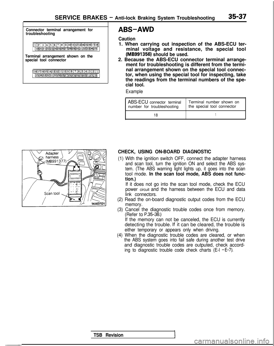
Connector terminal arrangement for
troubleshooting
[l I2 / 3 14 15 1617 16 I9[10~11~12(13~14~15(16~17[16j[lQ~20~21~22~23~24)25~26~27~28(29130~31~32~33~34~35~
Terminal arrangement shown on the
special tool connector
-.
TSB Revision
ABS-AWD
Caution
1. When carrying out inspection of the ABS-ECU ter-
minal voltage and resistance, the special tool
(MB991356) should be used.
2. Because the ABS-ECU connector terminal arrange- ment for troubleshooting is different from the termi-
nal arrangement shown on the special tool connec-
tor, when using the special tool for inspecting, take
the readings from the terminal numbers of the spe-
cial tool.
Example
ABS-ECU connector terminalTerminal number shown on
number for troubleshooting the special tool connector
181
CHECK, USING ON-BOARD DIAGNOSTIC
(1) With the ignition switch OFF, connect the adapter harness
and scan tool, turn the ignition ON and select the ABS sys-
tem. (The ABS warning light lights up, it goes into the scan
tool mode. In the scan tool mode, ABS does not func-
tion.)
If it does not go into the scan tool mode, check the ECU
power
circuit and the harness between the ECU and data
link connectors.
(2) Read the on-board diagnostic output codes from the ECU
memory.
(3) Cancel the diagnostic trouble codes once from memory. (Refer to
P.35-38.)
If the memory can not be canceled, the ECU is currently
detecting the trouble. If’it can be cleared, the trouble is
either temporary or appears only when driving.
(4) When the diagnostic trouble codes are cleared, or when
the ABS system goes into fail safe during another test drive
and diagnostic trouble codes are outputed, check accord-
ing to diagnostic trouble code check charts (E-l -E-7).
Page 1160 of 1273
SERVICE BRAKES- Anti-lock Braking System Troubleshooting35-39
AABS warning light does not light at all.1
[Explanation][Hint]
When it does not light up at all, there is a strongIf other warning lighrs do not light up either, fuse is
possibility that there is trouble with ABS warningprobably blown.
light or with power to the light.
MAIN FUSIBLELINK @of
LA
IGNITIONIGNITSWITCH (IG2)SWIT
-Tr-- -z
ABS POWERRELAY
‘IOct:I
1__--------I,7r
.I
:
,\c
AL1-f.
C.
dU
dr-3
gl”pzElzmq
4
4*I
21\5 ,&A27ABS ECU
;(IGI,
1234
7m5670
1
J/B
7
1COMBINATION
1METER
1r2
gizizgl
*
t
GNOGNDVV
*I:
Non-Turbo
TSB RevisionI
Page 1161 of 1273

SERVICE BRAKES - Anti-lock Braking System Troubleshooting
W
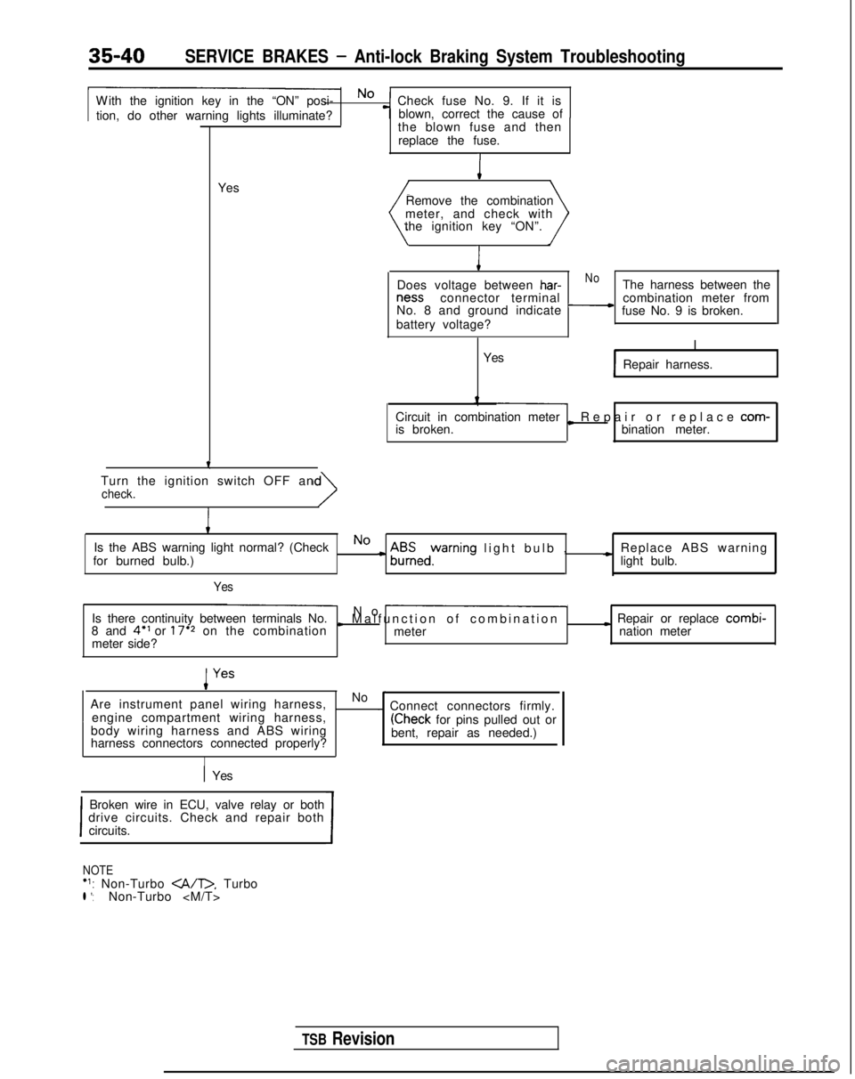
ith the ignition key in the “ON” posi- No
Check fuse No. 9. If it is
tion, do other warning lights illuminate? blown, correct the cause of
-T-
Yesthe blown fuse and then
replace the fuse.I
Remove the combination
meter, and check with
the ignition key “ON”.
I
Does voltage between har-NoThe harness between the ness
connector terminal
No. 8 and ground indicate
-combination meter from
fuse No. 9 is broken.
battery voltage?
I
Yes Repair harness.
Circuit in combination meter
is broken.
L Repair or replace com-
bination meter.
Turn the ignition switch OFF an
check.
I
Is the ABS warning light normal? (CheckNo
for burned bulb.)c A$Eedyrning light bulb
,
c Replace ABS warning
light bulb.
Yes
Is there continuity between terminals No. No -
8 and 4” or 17’2 on the combinationI Malfunction of combinatio
n
meter
I Repair or replace combi-
meter side? nation meter
Are instrument panel wiring harness, No
-~
engine compartment wiring harness, . Connect connectors firmly.
body wiring harness and ABS wiring
(Check for pins pulled out or
harness connectors connected properly? bent, repair as needed.)
I
1 Yes
I
Broken wire in ECU, valve relay or both
drive circuits. Check and repair both
circuits.
I
NOTE‘1: Non-Turbo . Turbol *:Non-Turbo
TSB Revision
Page 1162 of 1273
Page 1163 of 1273

SERVICE BRAKES - Anti-lock Braking System Troubleshooting35-41
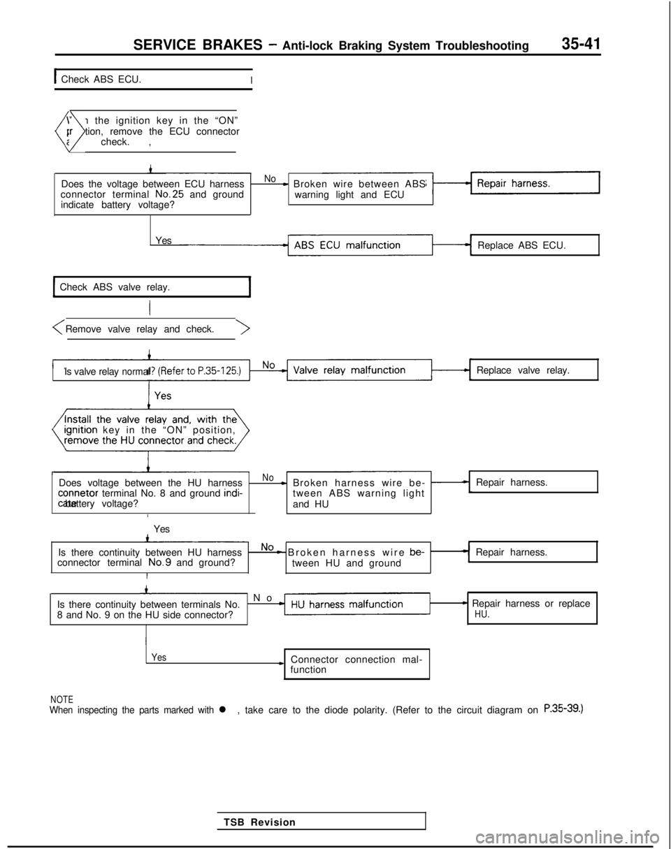
1 Check ABS ECU.I
W
ith the ignition key in the “ON”
position, remove the ECU connector
(nd check. ,)
Does the voltage between ECU harnessNo- Broken wire between ABS
connector terminal No.25
and ground
warning light and ECU
indicate battery voltage?
Yes Replace ABS ECU.
Check ABS valve relay.
Is valve relaynormalReplace valve relay.
I
rgnrtron key in the “ON” position,
Does voltage between the HU harness
No- Broken harness wire be- -Repair harness. connetor
terminal No. 8 and ground indi-
tween ABS warning lightcate battery voltage?
and HU
I
Yes
Is there continuity between HU harness
No - Broken harness wire be-
Repair harness.
connector terminal No.9
and ground?
tween HU and ground
I
’ N
o
Is there continuity between terminals No.
8 and No. 9 on the HU side connector?
- Repair harness or replaceHU.
Yes
* Connector connection mal- function
NOTEWhen inspecting the parts marked with l ,take care to the diode polarity. (Refer to the circuit diagram on R.S5-39.)
TSB Revision
Page 1165 of 1273
Page 1166 of 1273
SERVICE BRAKES - Anti-lock Braking System Troubleshooting35-45
DABS warning light blinks once after the ignition key is turned to the “\
ON” positi??. It
illuminates in the “START” position and blinks once again when tur\
ned to the “ON” posItron.
[Explanation]
When power flows, the ABS ECU turns on theharness between the ECU and the warning light, the
warning light for approximately 1 sec. while itlight illuminates only when the valve relay is off in
performs a valve relay test. If there is a break in thethe valve relay test, etc.
El
ABS ECU
11 ,* (3 14
1 5 j 6 1 ,I 8 I 9)10111112113114115l161171~8)[19~0p1l22~3lz4125126127129l29l,ol31l32l33l~l35l
‘1. Non-Turbo . Turbo‘2: Non-Turbo 14AO662
Removehydraulic unitconnector andABS-ECUconnector and inspect atthe ABS-ECUharness \side
connect:/
-.
TSB Revision
Yes
Replace ABS ECU.I
Page 1181 of 1273

35-60SERVICE BRAKES - Service Adjustment Procedures
Pad assembly
\
l4RO367
IWhen newWhen wornI
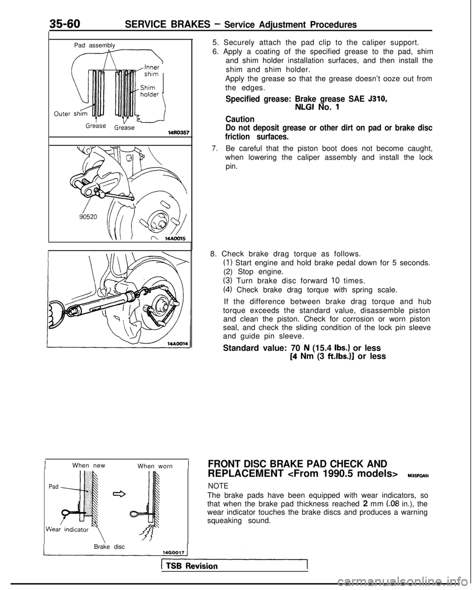
PadWea 5. Securely attach the pad clip to the caliper support.
6. Apply a coating of the specified grease to the pad, shim
and shim holder installation surfaces, and then install the
shim and shim holder.
Apply the grease so that the grease doesn’t ooze out from
the edges.
Specified grease: Brake grease SAE 5310,
NLGI No. 1
Caution
Do not deposit grease or other dirt on pad or brake disc
friction surfaces.
7.Be careful that the piston boot does not become caught,
when lowering the caliper assembly and install the lock pin.
8. Check brake drag torque as follows.
(1) Start engine and hold brake pedal down for 5 seconds.
(2) Stop engine.
(3) Turn brake disc forward IO times.
(4) Check brake drag torque with spring scale.
If the difference between brake drag torque and hub
torque exceeds the standard value, disassemble piston and clean the piston. Check for corrosion or worn piston
seal, and check the sliding condition of the lock pin sleeve
and guide pin sleeve.
Standard value: 70
N (15.4 Ibs.) or less
[4 Nm (3 ftlbs.)]
or less
FRONT DISC BRAKE PAD CHECK AND
REPLACEMENT Y35FaAH
NOTE
The brake pads have been equipped with wear indicators, so
that when the brake pad thickness reached 2 mm
(.08 in.), the
wear indicator touches the brake discs and produces a warning
squeaking sound.
Brake disc