1989 MITSUBISHI GALANT air condition
[x] Cancel search: air conditionPage 148 of 1273
13-6
FUEL SYSTEM
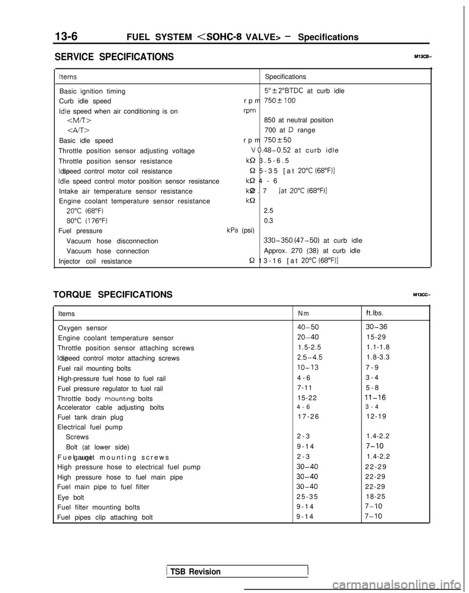
SERVICE SPECIFICATIONSMl3CE.
ItemsSpecifications
Basic ignition timing
5”?2”BTDC at curb idle
Curb idle speed rpm
7502 100Idle
speed when air conditioning is on rpm
-am-r>850 at neutral position
4A>700 at D range
Basic idle speed rpm
750+50
Throttle position sensor adjusting voltageV 0.48-0.52 at curb idl
e
Throttle position sensor resistance
k-2 3.5-6.
5
Idle speed control motor coil resistance
Q 5-35 [at 20°C (68”F)l
Idle
speed control motor position sensor resistance
M-2 4-
6
Intake air temperature sensor resistance kQ 2.7 [at
20°C (68”F)l
Engine coolant temperature sensor resistancekc2
20°C (68°F)2.5
80°C (176°F)0.3
Fuel pressurekPa (psi)
Vacuum hose disconnection
330-350 (47-50) at curb idle
Vacuum hose connection Approx. 270 (38) at curb idle
Injector coil resistance
R 13-16 [at 20°C (68”F)]
TORQUE SPECIFICATIONSMIICC-
Items
Oxygen sensor
Engine coolant temperature sensor
Throttle position sensor attaching screws Idle speed control motor attaching screws
Fuel rail mounting bolts
High-pressure fuel hose to fuel rail
Fuel pressure regulator to fuel rail
Throttle body mounting
bolts
Accelerator cable adjusting bolts
Fuel tank drain plug
Electrical fuel pump Screws
Bolt (at lower side)
Fuel unit mounting screws gauge
High pressure hose to electrical fuel pump
High pressure hose to fuel main pipe
Fuel main pipe to fuel filter
Eye bolt
Fuel filter mounting bolts
Fuel pipes clip attaching boltNmft.lbs.
40-5030-36
20-4015-29
1.5-2.5 1.1-1.8
2.5-4.51.8-3.3
IO-137-
9
4-6 3-4
7-11 5-8
15-22
11-16
4-
6
3-4
17-26 12-19
2-3 1.4-2.2
9-14
7-10
2-
3
1.4-2.2
30-4022-2
9
30-4022-29
30-4022-29
25-3
5
18-25
9-14
7-10
9-1
4
7-10
1 TSB Revision
Page 150 of 1273
13-8
FUEL SYSTEM
TROUBLESHOOTING
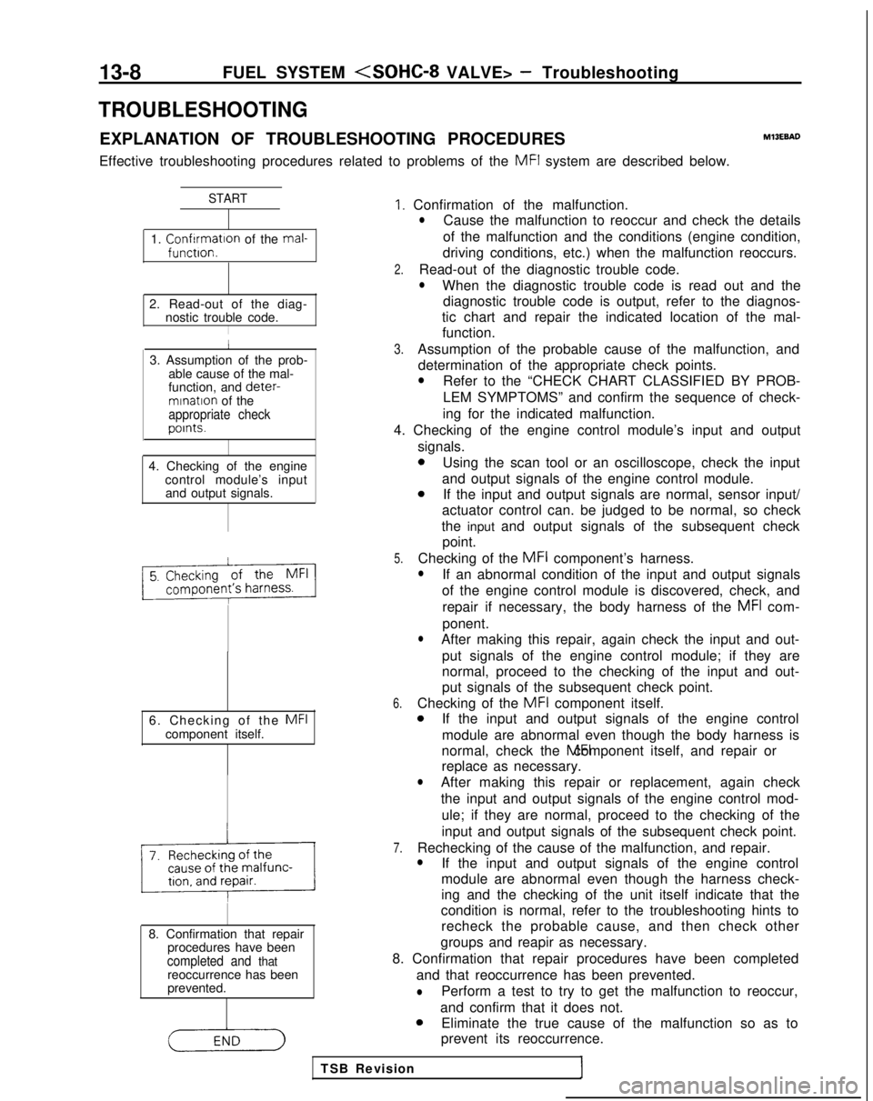
EXPLANATION OF TROUBLESHOOTING PROCEDURESMlBEBAD
Effective troubleshooting procedures related to problems of the MFI
system are described below.
START
1. Confrrmatron of the mal-functron.
2. Read-out of the diag-
nostic trouble code.
I
I
3. Assumption of the prob-
able cause of the mal-
function, and deter-
mrnatron of theappropriate checkpoints.
4. Checking of the engine
control module’s inputand output signals.
6. Checking of the
MFIcomponent itself.
8. Confirmation that repair procedures have been
completed and thatreoccurrence has been
prevented.
I. Confirmation of the malfunction.lCause the malfunction to reoccur and check the details
of the malfunction and the conditions (engine condition,
driving conditions, etc.) when the malfunction reoccurs.
2.Read-out of the diagnostic trouble code.
lWhen the diagnostic trouble code is read out and the diagnostic trouble code is output, refer to the diagnos-
tic chart and repair the indicated location of the mal- function.
3.Assumption of the probable cause of the malfunction, and
determination of the appropriate check points.
lRefer to the “CHECK CHART CLASSIFIED BY PROB-
LEM SYMPTOMS” and confirm the sequence of check-
ing for the indicated malfunction.
4. Checking of the engine control module’s input and output signals.
0Using the scan tool or an oscilloscope, check the input
and output signals of the engine control module.
aIf the input and output signals are normal, sensor input/
actuator control can. be judged to be normal, so check
the input and output signals of the subsequent check point.
5.Checking of the MFI
component’s harness.lIf an abnormal condition of the input and output signals
of the engine control module is discovered, check, and
repair if necessary, the body harness of the
MFI com-
ponent.
lAfter making this repair, again check the input and out- put signals of the engine control module; if they are
normal, proceed to the checking of the input and out-
put signals of the subsequent check point.
6.Checking of the MFI
component itself.aIf the input and output signals of the engine control
module are abnormal even though the body harness is
normal, check the MFI component itself, and repair or
replace as necessary.
lAfter making this repair or replacement, again check
the input and output signals of the engine control mod-
ule; if they are normal, proceed to the checking of the
input and output signals of the subsequent check point.
7.Rechecking of the cause of the malfunction, and repair.lIf the input and output signals of the engine control
module are abnormal even though the harness check-
ing and the checking of the unit itself indicate that the
condition is normal, refer to the troubleshooting hints to recheck the probable cause, and then check other
groups and reapir as necessary.
8. Confirmation that repair procedures have been completed and that reoccurrence has been prevented.
lPerform a test to try to get the malfunction to reoccur,
and confirm that it does not.
aEliminate the true cause of the malfunction so as to
prevent its reoccurrence.
TSB Revision
Page 153 of 1273
FUEL SYSTEM
ON-BOARD DIAGNOSTIC-
The engine control module monitors the input/out-
put signals (some signals at all times and the others
under specified conditions) of the engine control
module.
When it is noticed that an irregularity has continued
for a specified time or longer from when the irregu- lar signal is initially monitored, passing a certain
number, the engine control module judges that an
irregularity has occurred, memorizes the diagnostic
trouble code, and outputs the signal to the on-board
diagnostic output terminal.
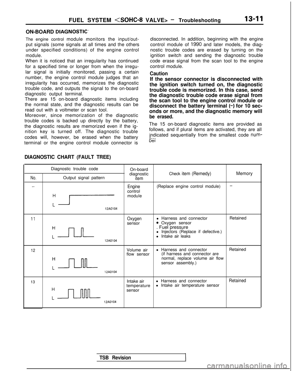
There are 15 on-board diagnostic items including
the normal state, and the diagnostic results can be
read out with a voltmeter or scan tool.
Moreover, since memorization of the diagnostic
trouble codes is backed up directly by the battery,
the diagnostic results are memorized even if the ig- nition key is turned off. The diagnostic trouble
codes will, however, be erased when the battery disconnected. In addition, beginning with the engine
control module of
1990 and later models, the diag-
nostic trouble codes are erased by turning on the
ignition switch and sending the diagnostic trouble
code erase signal from the scan tool to the engine
control module.
Caution
If the sensor connector is disconnected with
the ignition switch turned on, the diagnostic
trouble code is memorized. In this case, send
the diagnostic trouble code erase signal from
the scan tool to the engine control module or disconnect the battery terminal (-)
for 10 sec-
onds or more, and the diagnostic memory will
be erased.
The 15 on-board diagnostic items are provided as
follows, and if plural items are activated, they are all
indicated sequentially from the smallest code num-
I---
terminal or the engine control module connector is
uer
DIAGNOSTIC CHART (FAULT TREE)
No.
-
Diagnostic trouble code On-board
diagnostic
Check item (Remedy) MemoryOutput signal patternitem
-Engine(Replace engine control module)
control
:r
module 12A0104
11Oxygenl Harness and connector
Retained
sensor0 Oxygen sensor
:-JLJ--
. Fuel pressure
l Injectors (Replace if defective.)
l Intake air leaks 12A0104
12Volume air
l Harness and connector
Retained
flow sensor (if harness and connector are
:-JJ-M-
normal, replace volume air flow
sensor assembly.) 12A0104
13 Intake air
l Harness and connector
Retained
temperature l Intake air temperature sensor
:n
sensor 12A0104
TSB Revision
Page 158 of 1273
13-16
FUEL SYSTEM
FAILSAFE/BACK-UP FUNCTIONS LIST
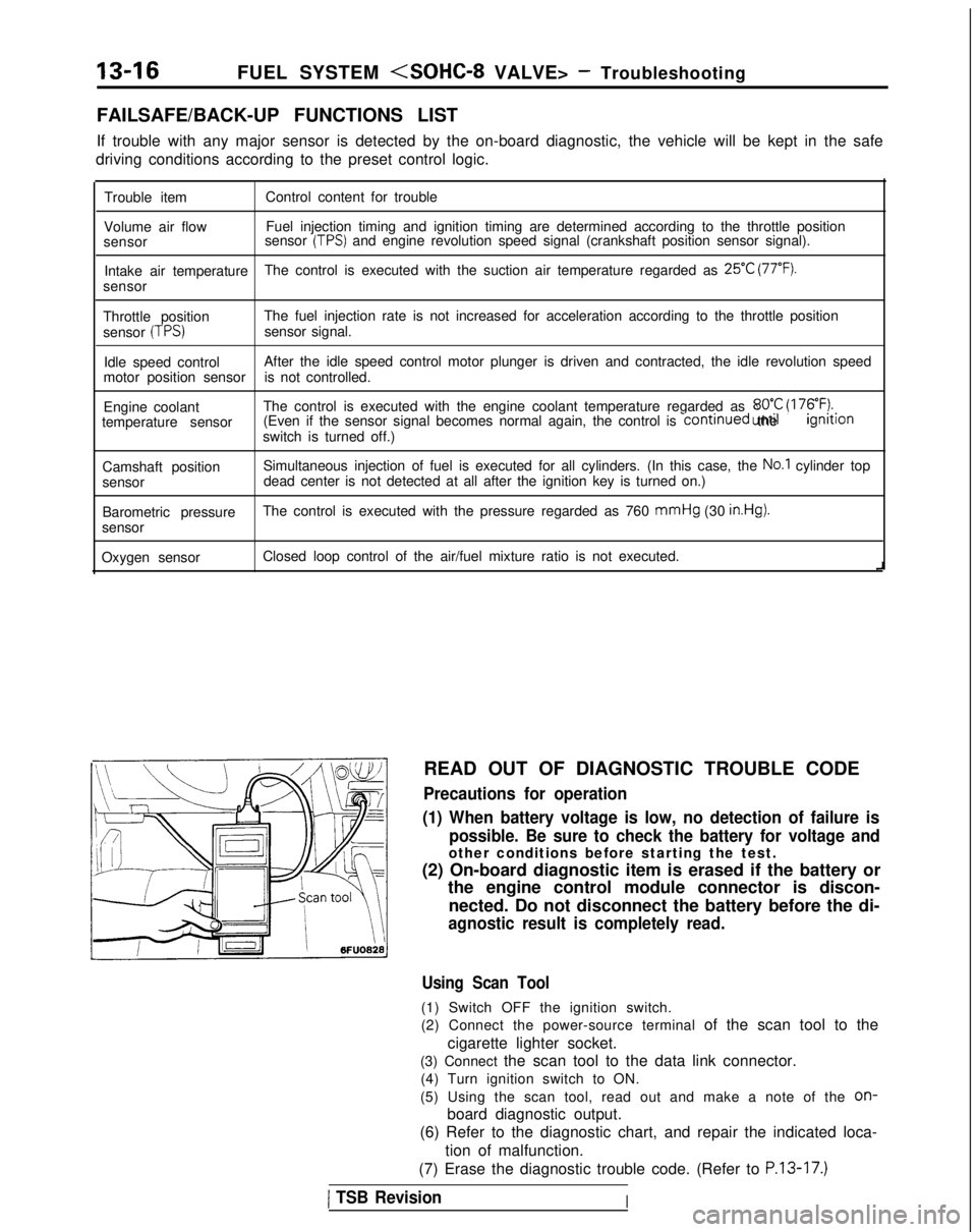
If trouble with any major sensor is detected by the on-board diagnostic,\
the vehicle will be kept in the safe
driving conditions according to the preset control logic.
Trouble item Control content for trouble
Volume air flow Fuel injection timing and ignition timing are determined according to th\
e throttle position
sensor sensor
(TPS) and engine revolution speed signal (crankshaft position sensor signal)\
.
Intake air temperature The control is executed with the suction air temperature regarded as
25°C (77°F).
sensor
Throttle position The fuel injection rate is not increased for acceleration according to t\
he throttle position
sensor
(TPS)sensor signal.
Idle speed control After the idle speed control motor plunger is driven and contracted, the\
idle revolution speed
motor position sensor is not controlled.
Engine coolant The control is executed with the engine coolant temperature regarded as \
8OO.C (176°F).temperature sensor (Even if the sensor signal becomes normal again, the control is continued
until the ignltlon
switch is turned off.)
Camshaft position Simultaneous injection of fuel is executed for all cylinders. (In this \
case, the
No.1 cylinder top
sensor dead center is not detected at all after the ignition key is turned on.)\
Barometric pressure The control is executed with the pressure regarded as 760 mmHg
(30
in.Hg).
sensor
Oxygen sensor Closed loop control of the air/fuel mixture ratio is not executed.
i
READ OUT OF DIAGNOSTIC TROUBLE CODE
Precautions for operation
(1) When battery voltage is low, no detection of failure is possible. Be sure to check the battery for voltage and
other conditions before starting the test.
(2) On-board diagnostic item is erased if the battery or the engine control module connector is discon-
nected. Do not disconnect the battery before the di-
agnostic result is completely read.
Using Scan Tool
(1) Switch OFF the ignition switch.
(2) Connect the power-source terminal of the scan tool to the
cigarette lighter socket.
(3) Connect the scan tool to the data link connector. (4) Turn ignition switch to ON.
(5) Using the scan tool, read out and make a note of the
on-
board diagnostic output.
(6) Refer to the diagnostic chart, and repair the indicated loca-
tion of malfunction.
(7) Erase the diagnostic trouble code. (Refer to
P.13-17.)
1 TSB RevisionI
Page 177 of 1273
FUEL SYSTEM
(14)Adjust the play of the accelerator cable. (Refer to P.13-
329.)
(15)Connect the idle-speed control motor’s connector.
(16)Adjust the throttle-position sensor.
(17)Start the engine again and let it run at idle speed for about
ten minutes; check to be sure that the idling condition is
normal.
THROTTLE BODY (THROTTLE VALVE AREA)
CLEANING
MllFlCK
(1)Start the engine and warm it up until the temperature of the
engine coolant reaches
80°C (176°F) or higher; then stop
the engine.
(2) Disconnect the air intake hose at the throttle body side.
(3) Spray cleaning liquid (from the intake port of the throttle body) onto the valve, and then leave as is for about fiveminutes.
(4) Start the engine and race it a few times; then let it run at idle speed for about one minute.
NOTE
If the engine idling speed is unstable (or the engine stalls),
let the engine run with the throttle valve slightly open.
(5) If deposits are not removed from the throttle valve, repeat steps (3) and (4).
(6) Connect the air intake hose.
(7) Using the scan tool, erase the diagnostic trouble code, or disconnect the battery’s ground cable for ten seconds orlonger and then reconnect it.
(8) Adjust the basic idle speed (engine speed adjusting screw). (Refer to
P.13-33.)
(9) Adjust the throttle position sensor.
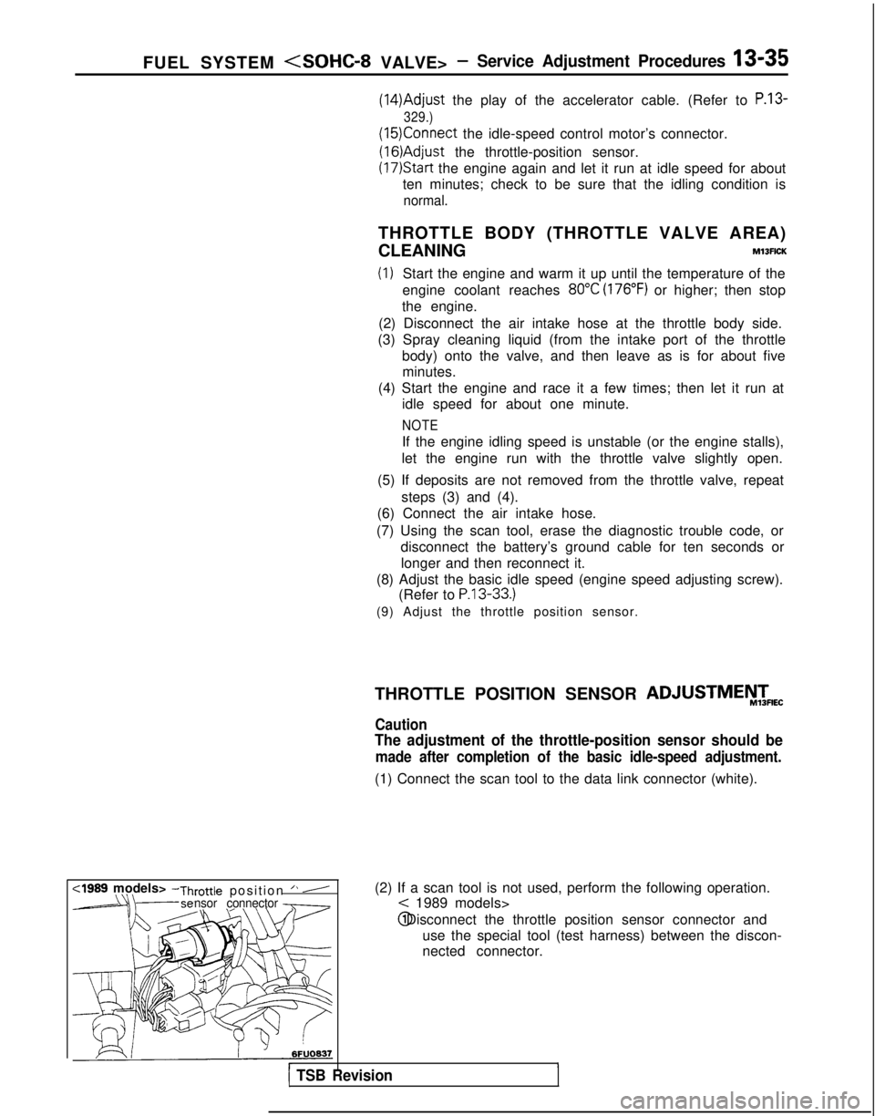
(2) If a scan tool is not used, perform the following operation.
< 1989 models> @ Disconnect the throttle position sensor connector and
use the special tool (test harness) between the discon-
nected connector.
r1 TSB Revision
THROTTLE POSITION SENSOR ADJUSTMEiW&
Caution
The adjustment of the throttle-position sensor should be
made after completion of the basic idle-speed adjustment.
(1) Connect the scan tool to the data link connector (white).
,
Page 180 of 1273
13-38
FUEL SYSTEM
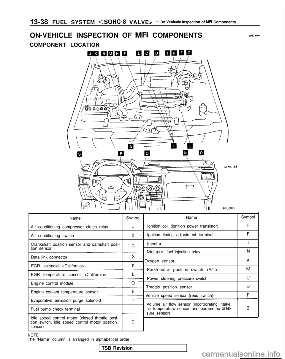
ON-VEHICLE INSPECTION OF MFI
COMPONENTS
COMPONENT LOCATION
Ii111 I‘I 1 II
bEM0148
6FUO843
M?BYA-
Name Symbol Name
Symbol
Air conditioning compressor clutch relay
JIgnition coil (ignition power transistor)F
Air conditioning switch 0Ignition timing adjustment terminalR
Crankshaft position sensor and camshaft posi- InjectorIGtion sensor-Multiport fuel injection relayN
Data link connectorS - Oxygen sensor
A
EGR solenoid
K-Park/neutral position switch M
EGR temperature sensor
L-Power steering pressure switchU
Engine control moduleQ- Throttle position sensorD
Engine coolant temperature sensorE- Vehicle speed sensor (reed switch)P
Evaporative emission purge solenoidHVolume air flow sensor (incorporating intake
Fuel pump check terminalTair temperature sensor and barometric pres-B
-sure sensor)
Idle speed control motor (closed throttle posi-
tion switch, idle speed control motor position
Csensor)
NOTEThe “Name” column is arranged in alphabetical order
TSB Revision
Page 183 of 1273
FUEL SYSTEM
Ciaarette
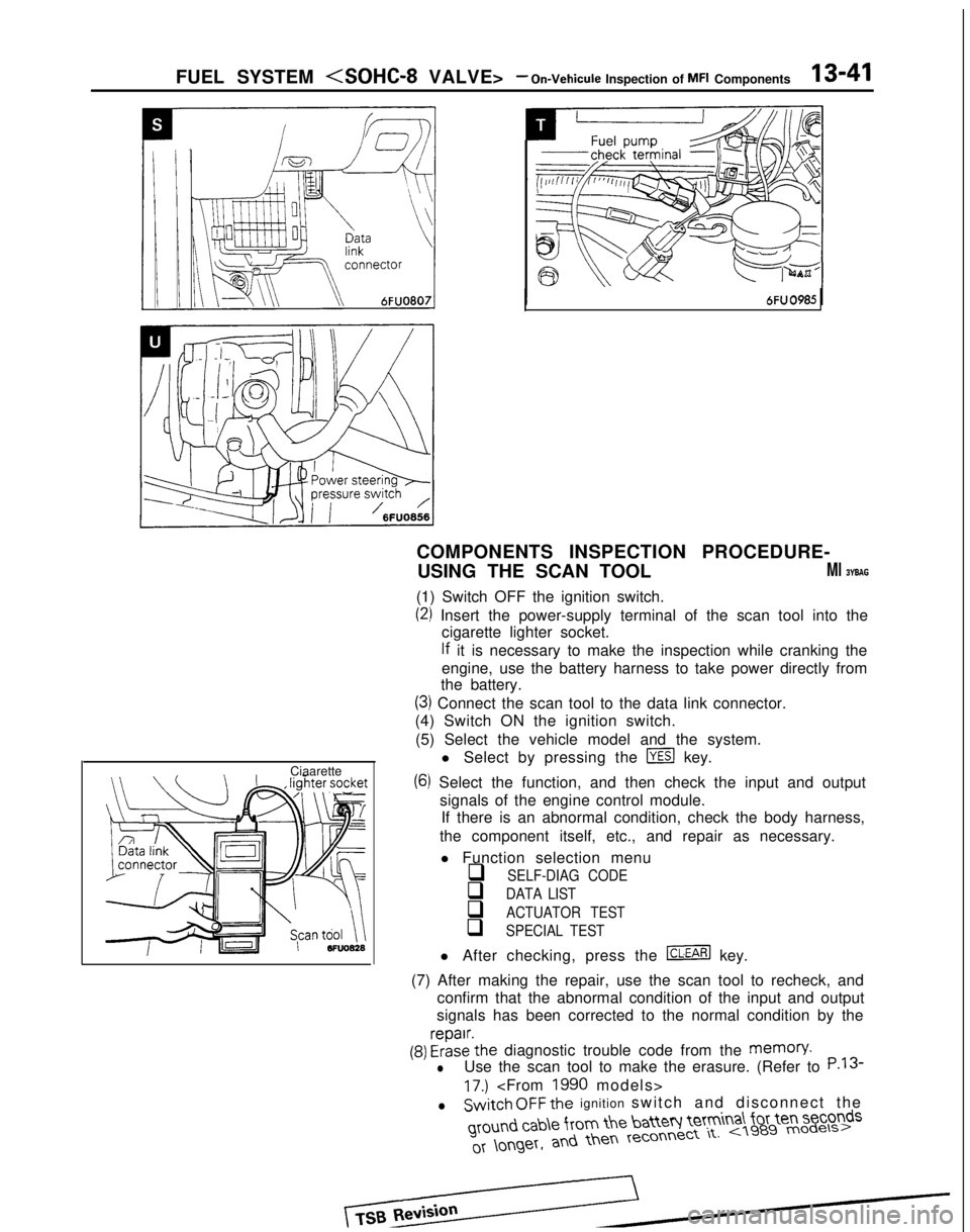
COMPONENTS INSPECTION PROCEDURE-
USING THE SCAN TOOL
Ml BYBAG
(1) Switch OFF the ignition switch.
(2) Insert the power-supply terminal of the scan tool into the cigarette lighter socket.
lf it is necessary to make the inspection while cranking the
engine, use the battery harness to take power directly from
the battery.
(3) Connect the scan tool to the data link connector.
(4) Switch ON the ignition switch.
(5) Select the vehicle model and the system. l Select by pressing the
m key.
(6) Select the function, and then check the input and outputsignals of the engine control module.If there is an abnormal condition, check the body harness,
the component itself, etc., and repair as necessary.
l Function selection menu
q SELF-DIAG CODE
q DATA LIST
q ACTUATOR TEST
q SPECIAL TEST
l After checking, press the m key.
(7) After making the repair, use the scan tool to recheck, and confirm that the abnormal condition of the input and output
signals has been corrected to the normal condition by the
(9) FrizE’the diagnostic trouble code from the memory.
lUse the scan tool to make the erasure. (Refer to P.13
17.)
lSwitch OFF the ignition switch and disconnect the ground
cab\e from the batteq Ie’tm
a\ for ten seconds
Page 184 of 1273
13-42 FUEL SYSTEM
(9) Switch OFF the ignition switch. (10)Disconnect
the scan tool. (11)Restart
the engine and perform a driving test, etc. to
confirm that the malfunction has been corrected.
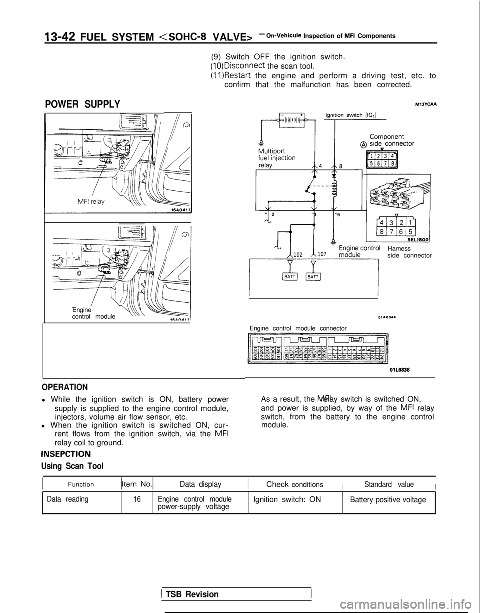
POWER SUPPLY
Engine
control moduleu\\ v
OPERATION
l While the ignition switch is ON, battery power
supply is supplied to the engine control module,injectors, volume air flow sensor, etc.
l When the ignition switch is switched ON, cur-
rent flows from the ignition switch, via the MFI
relay coil to ground.
INSEPCTION
Using Scan Tool
relay ’
\/\/\/“
2
“3 “6
CL I 4,
Harness
side connector
Engine control module connector OlLO838
As a result, the MFI relay switch is switched ON,
and power is supplied, by way of the
MFI relay
switch, from the battery to the engine control
module.
IFunctionData displayICheck conditionsIStandard valueI
Data reading16Engine control modulepower-supply voltageIgnition switch: ONBattery positive voltage
1 TSB Revision