Page 207 of 1273
FUEL SYSTEM - On-Vehicule Inspection of MFI Components13-65
(1) Improper adjustment of the basic idling speed.
(2) Deposits adhering to the ttirottle valve.
(3) Air being taken into the intake manifold due to a gasket leak, etc.
OPERATION
ISC motor position sensor is a variable resistor type,
and is integrated in the
ISC motor system. The slid-
ing pin of
ISC motor position sensor is in contact
with the end of the plunger. Therefore, as the plun- ger moves, the internal resistance of
ISC motor pos-
ition sensor varies. This leads to the variation of the (4) Improper seating of the EGR valve seat.
(5) lmcomplete combustion within a cylinder. (Mal-
function of spark plugs, ignition coil, injectors,
compression pressure, etc.)
the plunger position of the
ISC motor system, and
sends the signal to ECM. ECM processes the
ISC
motor position sensor signal, idle signal, coolant
temperature signal, load signal (A/T &
A/C) and ve-
hicle speed signal to control the opening angle of
the throttle valve and revolution speed during
en-
output voltage. ISC motor position sensor detects gine idling.
TROUBLESHOOTING HINTS
Since idling is not controlled when ISC motor posi-
tion sensor is troubled, idling may not be evenly
maintained.
INSPECTION
Using Scan tool
FunctionItem No. Data display Inspection conditions Load conditions
Standard value
Data reading 15 Sensor detec-
. Engine coolant tempera-
Air conditioning 500- 1,300 mV
tion voltage
ture: 85-95’C (185-203°F)
switch: OFF
. Lights, cooling fan, electrical accessories: OFF Air conditioning 800-
1,800 mV. Transaxle: neutral (A/T
mod-
switch: ON
els: “P”
range)
1 Closed throttle position Air conditioning900- 1,900 mVswitch: ON (The compressorswitch: ON
clutch must be operating Select lever:
when the air conditioning shift to “D”
switch is ON.)
range.* Engine: running at idle
NOTEThe idle speed control motor position sensor output voltage may be about\
500 mV higher than indicated above when
the vehicle is new [driven approximately 500 km (300 miles) or less].
CautionBefore shifting the select lever to the “D” range, apply the brake\
s to prevent the vehicle from moving forward.
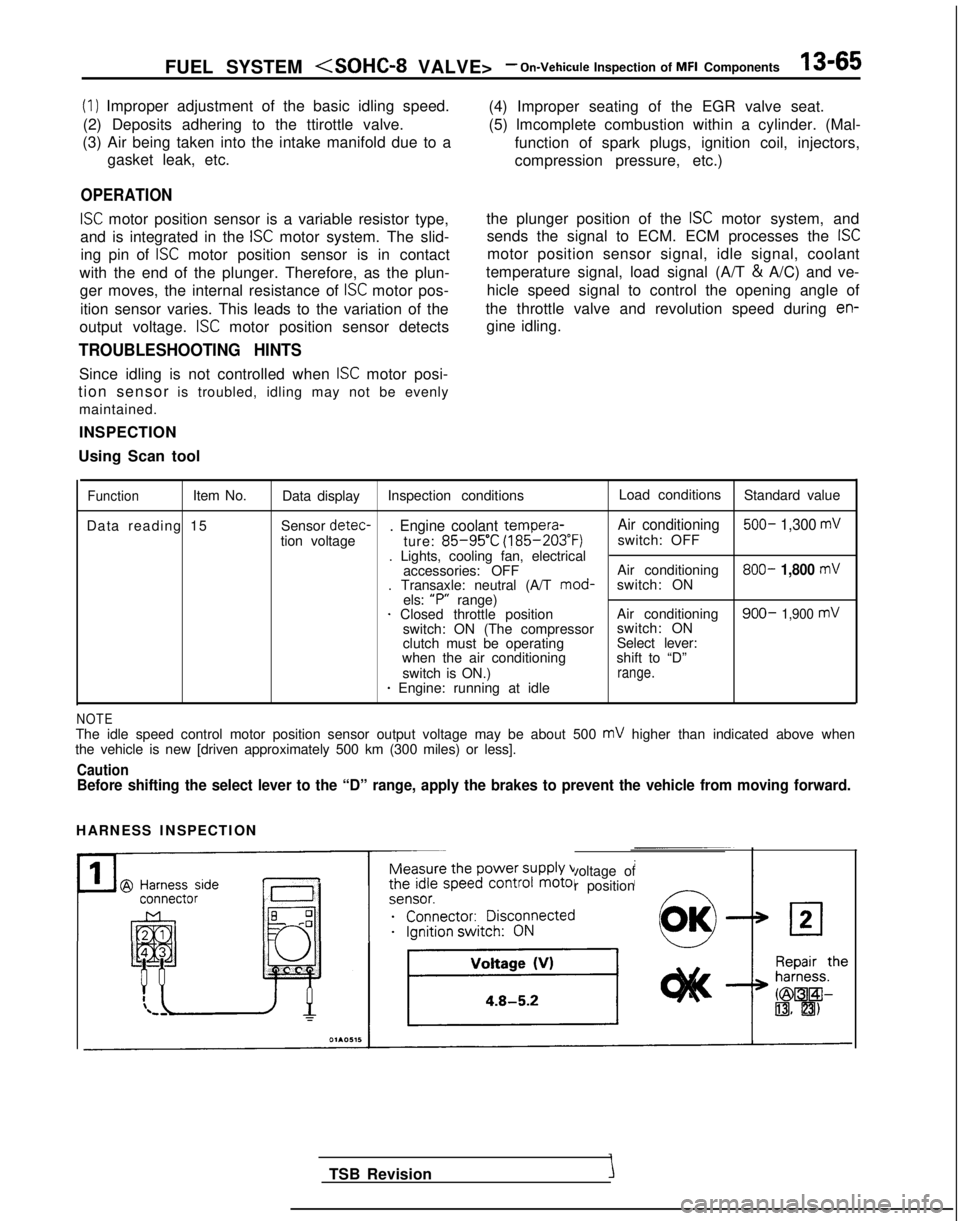
HARNESS INSPECTION
Measure the power supply voltage of
the idle speed control motor position
ei;;;it;;sco$ected
__...._ -.-
TSB Revision
Page 219 of 1273
FUEL SYSTEM -On-Vehicule Inspection of MFI CmpOnentS13977
IGNITION SWITCH-ST
>
Engine control module connector
II
Enginecontrolmodule01 LO838
Ignition switch (ST)
7
Tr108104
T-7JL
6FU1257
OPERATION
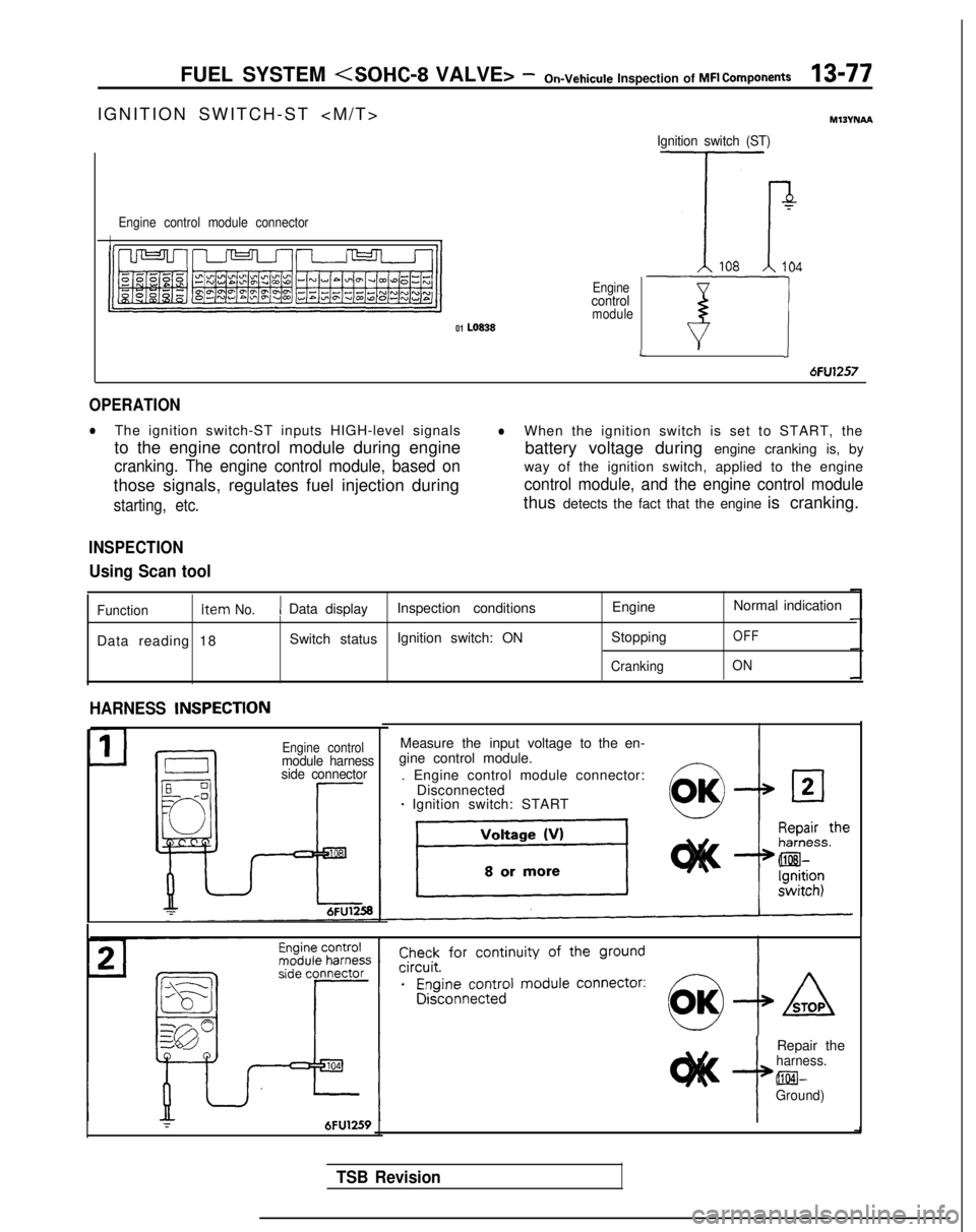
lThe ignition switch-ST inputs HIGH-level signalslWhen the ignition switch is set to START, the
to the engine control module during engine battery voltage during engine cranking is, by
cranking. The engine control module, based onway of the ignition switch, applied to the engine
those signals, regulates fuel injection during
control module, and the engine control module
starting, etc.thus detects the fact that the engine is cranking.
INSPECTION
Using Scan tool
Function Item No.1 Data display
Inspection conditions EngineNormal indication
Data reading 18 Switch status
Ignition switch: ON
Stopping
OFF
CrankingON
HARNESS INSPECTlON
Engine controlmodule harness
side connector
Measure the input voltage to the en-
gine control module.
. Engine control module connector: Disconnected
- Ignition switch: START
r6FU1259i
Repair theharness. @El-
Ground)
TSB Revision
Page 221 of 1273
FUEL SYSTEM - On-Vehicule Inspection of MFI Components13-79
INSPECTION
Using Scan tool
Ignition switch-ST
Function Item No.Data display Check conditions
EngineNormal display
Data reading 18 Switch status
. Ignition switch: ON Stopped
OFF
CrankingON
Park/neutral position switch
Function
Item No.Data display
Check conditions Selector lever position
Normal display
Data reading 29 Shift position
. Ignition
swatch: ON Por NPor N
D, 2, Lor RD, 2, L or R
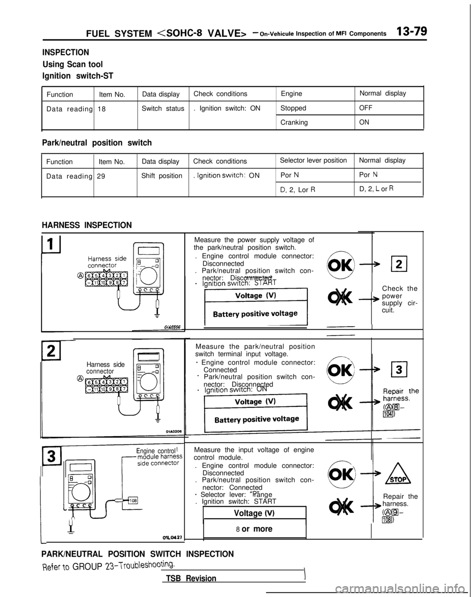
HARNESS INSPECTION
Harness sideconnector
Engine control
Measure the input voltage of engine
control module.
. Engine control module connector: Disconnected
. Park/neutral position switch con-
nector: Connected
* Selector lever: “P” range
. Ignition switch: START
Voltage (V)
:
1
Y-OlLO42’f
PARK/NEUTRAL POSITION SWITCH INSPECTION
Measure the power supply voltage of
the park/neutral position switch.
. Engine control module connector: Disconnected
. Park/neutral position switch con-
nector: Disconnected
Check the
I+
power
supply cir-
cuit.
Measure the park/neutral position
switch terminal input voltage.
* Engine control module connector: ConnectedPark/neutral position switch con-
nector: Disconnected
8 or more
ASTOP
Repair the
harness.
C@W lIEI)
Refer to GROUP 23-Troubleshooting.
TSB RevisionI
Page 225 of 1273
FUEL SYSTEM -On-Vehicule
inspection of MFI Components13-83
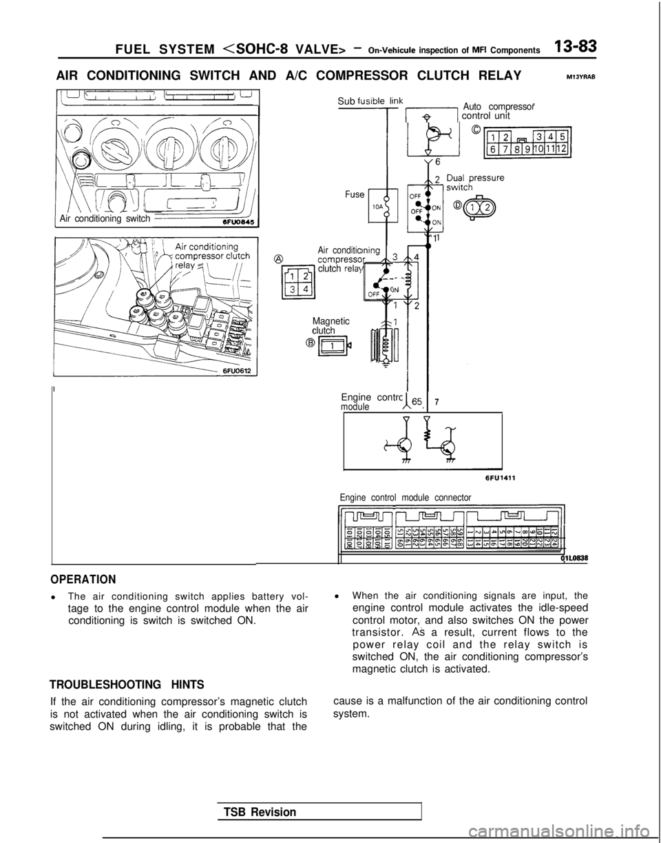
AIR CONDITIONING SWITCH AND A/C COMPRESSOR CLUTCH RELAYM13YRAE
Air conditioning switch
Sub fl
FUSC?
Air conditic@compresscclutch relal
Magnetic
clutch
Jsibie li
7
)ningIr /k
!Ik 171 control unitAuto compressor
-
-
)N
Engine control 65moduleA I7
‘1
6FU1411
Engine control module connector
IhJ-Jl r--vrJ=-Jl/l
OlLO838
OPERATION
l
The air conditioning switch applies battery vol-
tage to the engine control module when the air
conditioning is switch is switched ON.
TROUBLESHOOTING HINTS
If the air conditioning compressor’s magnetic clutch
is not activated when the air conditioning switch is
switched ON during idling, it is probable that the l
When the air conditioning signals are input, the
engine control module activates the idle-speed
control motor, and also switches ON the power
transistor.
AS a result, current flows to the
power relay coil and the relay switch is
switched ON, the air conditioning compressor’s
magnetic clutch is activated.
cause is a malfunction of the air conditioning control
system.
TSB Revision
Page 226 of 1273
13-84 FUEL SYSTEM - On-Vehicule Inspection of MFI Components
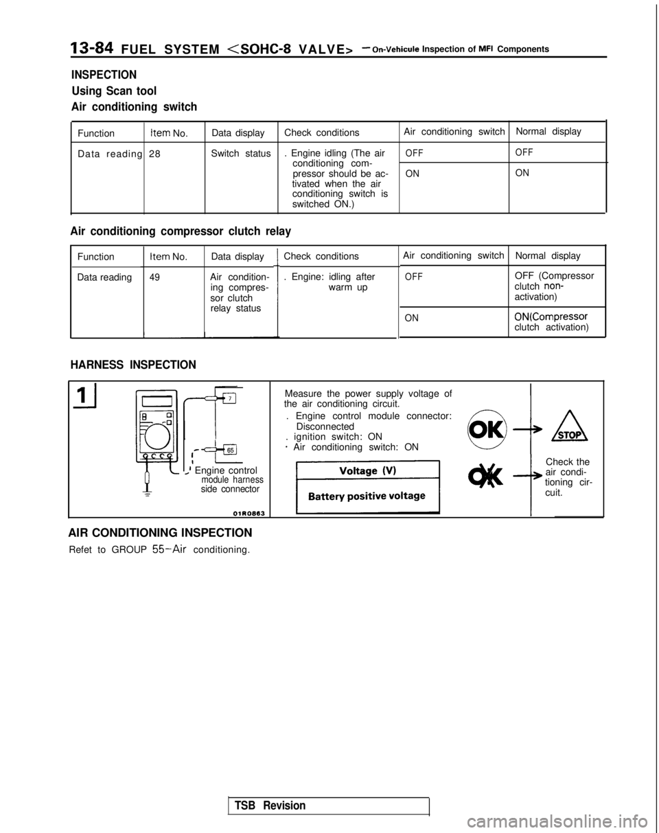
INSPECTION
Using Scan tool
Air conditioning switch
Function Item
No.
Data reading 28 Data display
Check conditions Air conditioning switch
Normal display
Switch status . Engine idling (The air
OFF OFFconditioning com-
pressor should be ac-ON ONtivated when the air
conditioning switch is
switched ON.)
Air conditioning compressor clutch relay
Function
Data reading Item
No. Data display
49Air condition-
ing compres-
sor clutch relay status Check conditions
. Engine: idling after
warm up
HARNESS INSPECTION
Air conditioning switch Normal display
OFFOFF (Compressor
clutch non-activation)
ON ON(Compressor
clutch activation)
,--=+aI_I Engine controlmodule harnessside connector
OlROB13
Measure the power supply voltage of
the air conditioning circuit.
. Engine control module connector: Disconnected
. ignition switch: ON
* Air conditioning switch: ON4
ASTOP
Check the
air condi-
tioning cir-
cuit.
AIR CONDITIONING INSPECTION Refet to GROUP
55-Air conditioning.
TSB Revision
Page 230 of 1273
13-88 FUEL SYSTEM
VALVE>- On-Vehicule Inspection of MFI Components
TROUBLESHOOTING HINTS
Hint I’
The exhaust gas purification performance will
Examples:
(1) Malfunction of an injector.
worsen if there is a malfunction of the oxygen sensor. Hint 2:
If the oxygen sensor output voltage deviates from
the standard value even though the results of the
checking of the oxygen sensor are normal, the
cause is probably a malfunction of a component related to mixture control. (2) Air leakage into the intake manifold from a
leaking gasket.
(3) Malfunction of the volume air flow sensor, the intake air temperature sensor, the barometric-
pressure sensor, or the engine coolant tempera-
ture sensor.
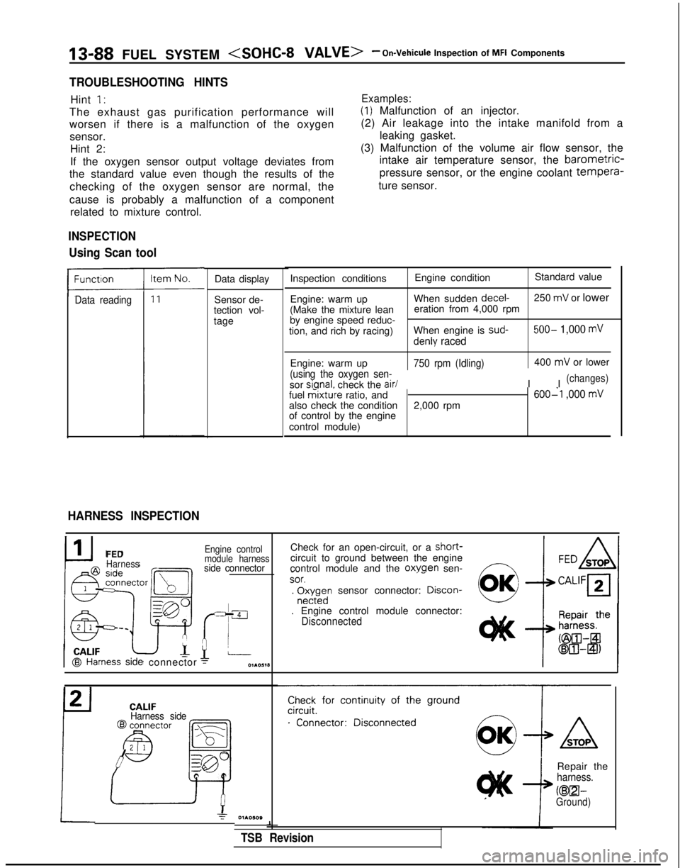
Data reading
INSPECTION
Using Scan tool
HARNESS INSPECTION
Data display
Sensor de-
tection vol-
tage Inspection conditions
Engine conditionStandard value
Engine: warm up When sudden decel-
250
mV or lower
(Make the mixture lean eration from 4,000 rpm
by engine speed reduc-
tion, and rich by racing) When engine is sud-
500- 1,000 mV
denly raced
Engine: warm up750 rpm (Idling)
(using the oxygen sen-
sor sianal.
check the air/
400
mV or lower
I I
(changes)
fuel mixture ratio, and600-l ,000 mValso check the condition 2,000 rpm
of control by the engine
control module)
I CALIF@I Hal
FEDHarness
ness
side
connector
Engine control
module harness
side connector
Check for an open-circuit, or a short-circuit to ground between the engine
control module and the oxwen sen-f7 _-
~~SOT.‘-. r$;rdn sensor connector: Drscon-
. Engine control module connector:Disconnected CALIF
Harness side
Check for continuity of the ground
.“‘..“...;;”
Repair theharness.
KEEI-Ground)
1
TSB Revision
Page 235 of 1273
FUEL SYSTEM -On-Vehicule Inspection of MFI Components13-93
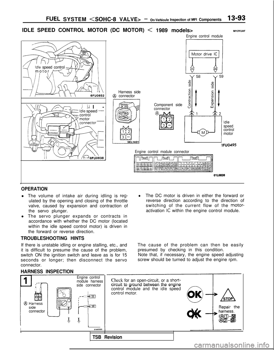
IDLE SPEED CONTROL MOTOR (DC MOTOR)
Idle speed control9-/
motor
/---T-,I \
6FUO852
i id l
-
Idle speed -control
r1 /&46~U0838
Harness side@ connector
< 1989 models>
Enoine control module
M13YUAF
Component sideconnector
!
a,Yg
z.-t;Fs 8
B
12
d
Idle
speed
control
Mmotor
lFUO495
Engine control module connector
1
OPERATION
l The volume of intake air during idling is reg-
ulated by the opening and closing of the throttle
valve, caused by expansion and contraction of
the servo plunger.
l The servo plunger expands or contracts in accordance with whether the DC motor (located
within the idle speed control motor) is driven in
the forward or reverse direction.
lThe DC motor is driven in either the forward or reverse direction according to the direction of
switching of the current flow of the motor-
activation
IC within the engine control module.
TROUBLESHOOTING HINTS
If there is unstable idling or engine stalling, etc., and
it is difficult to presume the cause of the problem,
switch ON the ignition switch and leave as is for 15
seconds or longer; then disconnect the servo
connector.
HARNESS INSPECTION
The cause of the problem can then be easily presumed by checking in this condition.Note that, if necessary, the engine speed adjusting
screw should be turned to adjust the engine rpm.
Iconnector
Engine control
module harness
side connector
IIrIsEI
r- r-
II01.03,~I
TSB Revision
Check for an open-circuit, or a short-circuit to ground between the engine
Page 241 of 1273
FUEL SYSTEM
VALVE>- On-Vehicule lnsuection of MFI Components13-99
EVAPORATIVE EMISSION PURGE SOLENOIDMlBYwAA
Multiport fuel injection
@ Harness sideconnector Componentside connector
i
5EL1206
Engine
control
module
TSB Revision
Evaporative emission
62
Engine control module connectorI,
OlLO838
OPERATION
l The evaporative emission purge solenoid is an
ON/OFF type of solenoid valve;
it functions to
regulate the introduction of purge air from the
evaporative emission canister to the intake
manifold plenum.
INSPECTION
Using Scan tool
lBattery power supply is supplied, by way of the multiport
fuel injection, to the evaporative emis-
sion purge solenoid. When the engine control
module switches ON the power transistor
within the unit, current flows to the coil, and
purge air is introduced.
IFunction1 Item No. 1 Activation1 Check conditions1 Normal condition
Actuator test 08 Solenoid valve is switched from . Ignition switch: ON
Operating sound is heard
OFF to ON.when driven.