1989 MITSUBISHI GALANT air condition
[x] Cancel search: air conditionPage 341 of 1273
FUEL SYSTEM
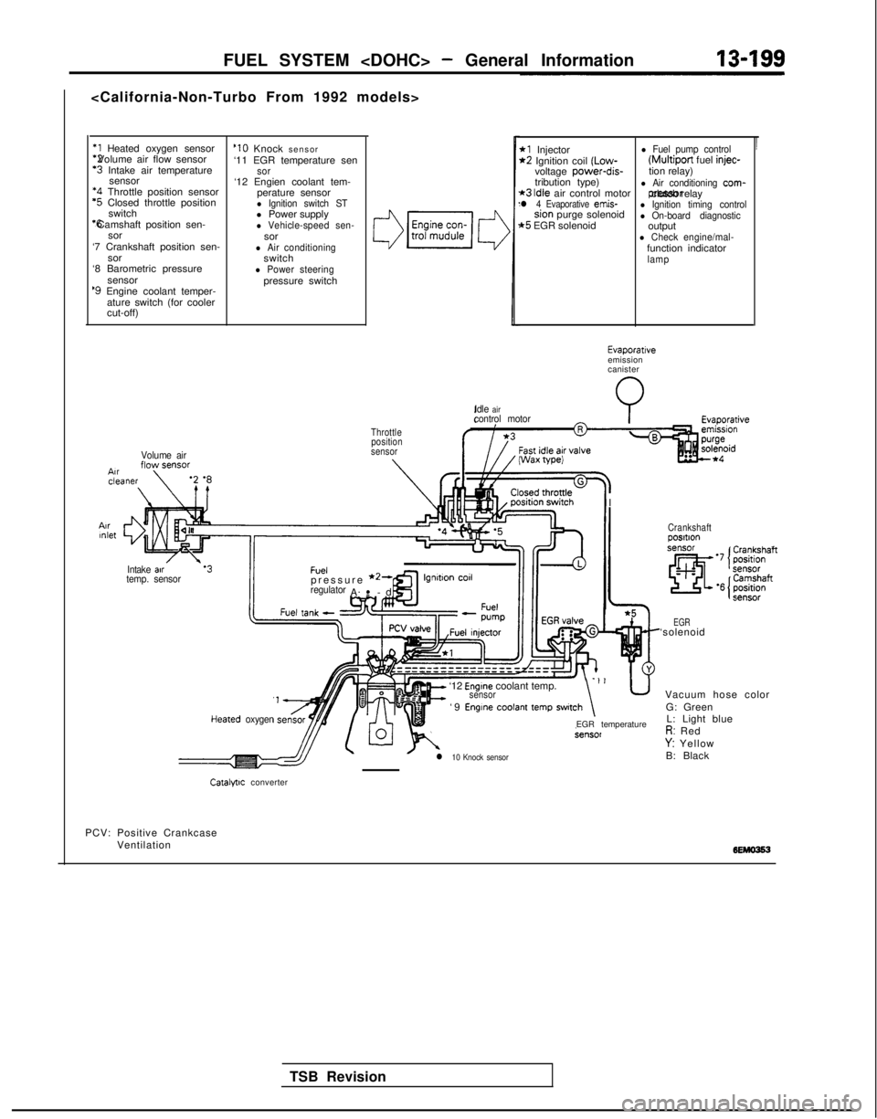
*1 Heated oxygen sensor *2 Volume air flow sensor
‘3 Intake air temperature
sensor *4
Throttle position sensor
‘5 Closed throttle position
switch *6 Camshaft position sen-
sor
‘7 Crankshaft position sen- sor
‘8 Barometric pressure
sensor
‘9 Engine coolant temper-ature switch (for cooler
cut-off)
Volume air
‘10 Knock sensor
‘11 EGR temperature sen
sor‘12 Engien coolant tem- perature sensor
l Ignition switch STl Power supplyl Vehicle-speed sen-sorl Air conditioningswitchl Power steeringpressure switch
3
Throttleposition
sensor
IIntake air.‘3Fueltemp. sensorpressure *2-regulatorA-
-
.
cd
’
*l Injectorl Fuel pump control*2 Ignition coil (Low- (Multiport
fuel injec-voltage power-dis-
tion relay)
tribution type)
*3 Idle air control motorl Air conditioning com-
l 4 Evaporative emis- pressor clutch relaysion purge solenoidl Ignition timing control
t5 EGR solenoidl On-board diagnosticoutputl Check engine/mal-function indicatorlamp
Idle
aircontrol motorI Wax
wei
I
I
TSB Revision
Evaporativeemission
canister
Heared oxygen
It=
‘12 Engine coolant temp.sensor-‘I u
‘9 Engine coolant temp switch\
l 10 Knock sensor
EGR temperature
Crankshaftposltlon
EGR‘solenoid Vacuum hose colorG: GreenL: Light blue
R: RedY: Yellow
B: Black
Catalfllc converter
PCV: Positive Crankcase Ventilation
Page 342 of 1273
13-200FUEL SYSTEM
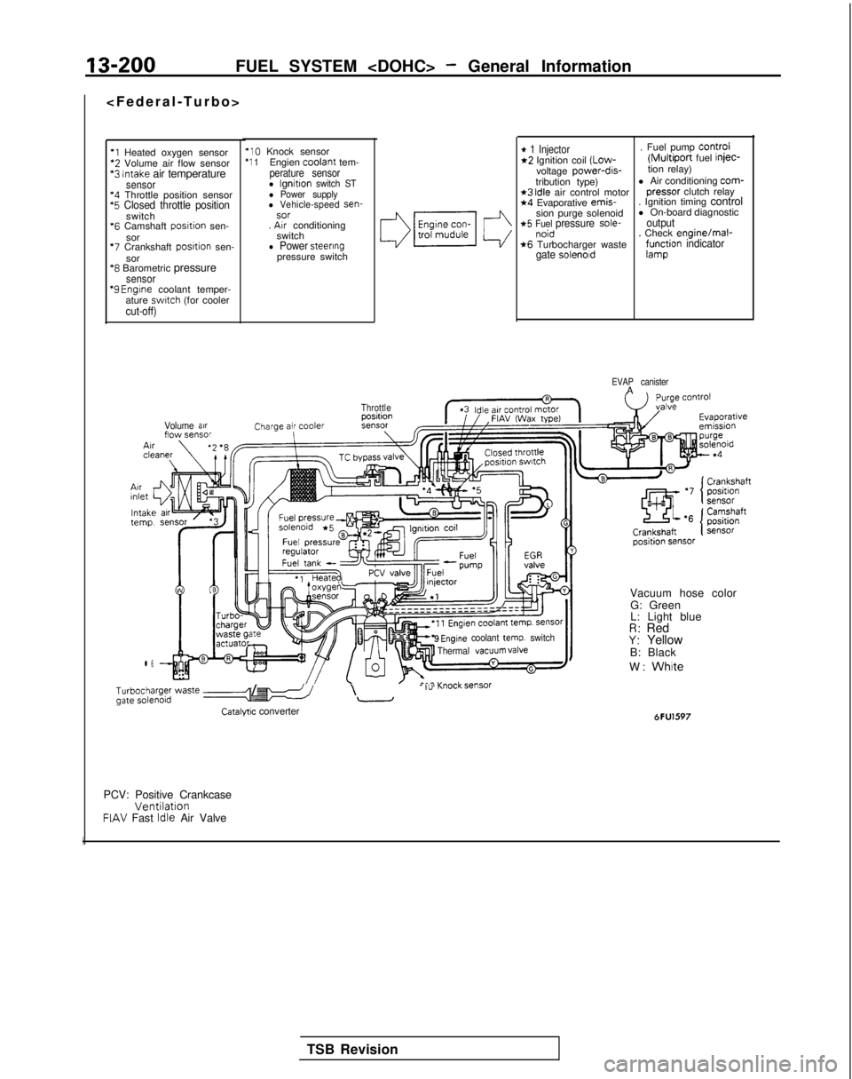
*l Heated oxygen sensor‘2 Volume air flow sensor*3 Intake air temperaturesensor‘4 Throttle position sensor‘5 Closed throttle positionswitch
*6
Camshaft posrtion sen-
sor
‘7 Crankshaft posrtion sen-
sor
‘8 Barometric pressuresensor “9
Engrne coolant temper-
ature swatch (for coolercut-off)
‘10 Knock sensor‘1 1Engien coolant
tem-perature sensorl lgnitton switch STl Power supplyl Vehicle-speed sen-sor. Arr conditioning
switch
l Power steeringpressure switch
Volume arrflow sensor
l 6
* 1 Injector. Fuel pump Control*2 Ignition coil (Low-(Multiport fuel injec-
voltage power-dis-tion relay)
tribution type) l Air conditioning com-
*3 Idle air control motor
pressor
clutch relay*4 Evaporative emis-
. Ignition timing control
sion purge solenoid l On-board diagnostic
*5 Fuel pressure sole-outputnoid. Check enginelmal-*6 Turbocharger wastegate solenoidf;r$ion indicator
EVAP canisterA
Throttle
9 Engine coolant temp. switch
Thermal VaCUUm valve
b;~ype; waste e-5 /I\- I”-
Catalyw converter
Vacuum hose color
G: Green
L: Light blue
R: RedY: Yellow
B: Black
W:
White
6FU1597
PCV: Positive CrankcaseVentilationFIAV Fast Idle Air Valve
I
TSB Revision
Page 343 of 1273
FUEL SYSTEM
I-
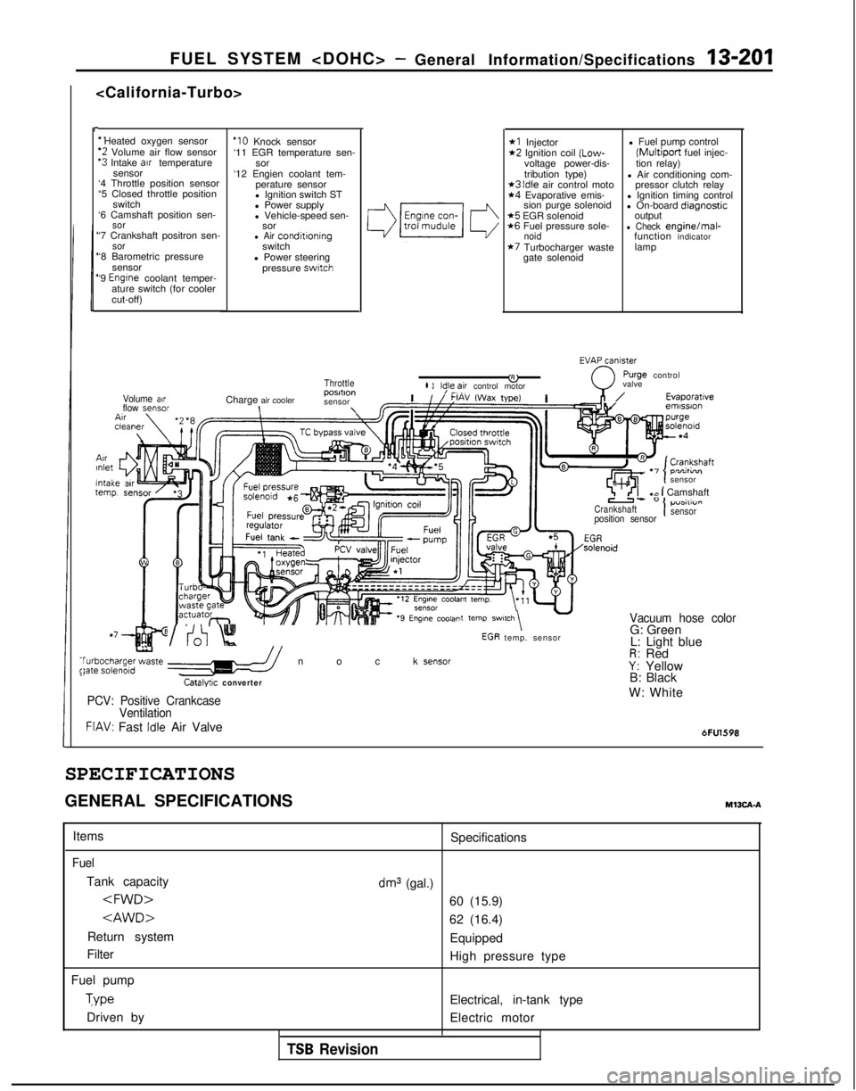
‘1 Heated oxygen sensor
‘2 Volume air flow sensor‘3 Intake arr temperature
sensor
‘4 Throttle position sensor
“5 Closed throttle position
switch
‘6 Camshaft position sen-
sor‘7 Crankshaft positron sen-sor‘8 Barometric pressure
sensor
‘9
Engrne coolant temper-
ature switch (for cooler
cut-off)
ArrInlet
lntaltern1
Volume airflow sensor
‘IO Knock sensor
‘11 EGR temperature sen- sor
‘12 Engien coolant tem- perature sensor
l Ignition switch ST
l Power supply
l Vehicle-speed sen- sor
l Air conditroningswitch
l Power steering pressure
swatch
Throttle
Charge air cooler posmon
sensor\\
*I Injector*2 Ignition coil (Low-
voltage power-dis-
tribution type)
*3 Idle air control moto*4 Evaporative emis- sion purge solenoid
*5 EGR solenoid*6 Fuel pressure sole-noid*7 Turbocharger waste
gate solenoid l Fuel pump control
(Multiport fuel injec-
tion relay)
l Air conditioning com- pressor clutch relay
l Ignition timing control
l On-board diaanostic
output
-l Check enginelmal-
function indicator
lamp
EVAxniy
&0
rurge controll 3ld,le,~ir control motor valve
,n/Evaporatrveemrssron
\tcln-^- temp. sensor
,Ir I-, . -,
sensor
7 ’ <‘I+c 1 Camshaft
Crankshaft1p”3111”I I
position sensorsensor
it
temp SWl,Ch\ -Vacuum hose color
t
WV:0 Knock sensor$bgha;ge;zte //
Catalyuc converter
G: Green
L: Light blue
R: RedY: Yellow
B: Black
PCV: Positive Crankcase
VentilationW: White
FIAV: Fast Idle Air Valve6FU1598
SPECIFICATIONS
GENERAL SPECIFICATIONSM13CA-A
Items
Fuel
Tank capacity
Return system
Filter
Fuel pump Type
Driven by Specifications
dm3 (gal.)
60 (15.9)
62 (16.4)
Equipped
High pressure type
Electrical, in-tank type
Electric motor
TSB Revision
Page 345 of 1273
FUEL SYSTEM
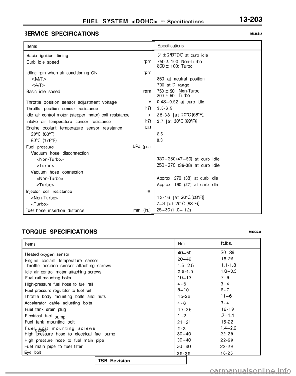
iERVlCE SPECIFICATIONS
Items
Basic ignition timing
Curb idle speed rpm
Idling rpm when air conditioning ON
vm
Basic idle speedrm
Throttle position sensor adjustment voltageV
Throttle position sensor resistance kQ
Idle air control motor (stepper motor) coil resistance a
Intake air temperature sensor resistance kQ
Engine coolant temperature sensor resistance
kS2
20°C (68°F)
80°C (176°F)
Fuel pressurekPa (psi)
Vacuum hose disconnection
Vacuum hose connection
Injector coil resistance a
Qel hose insertion distance mm (in.)
TORQUE SPECIFICATIONS
Ml3CGA
m13caA
Specifications
5”
f 2”BTDC at curb idle
750
+ 100: Non-Turbo800? 100: Turbo
850 at neutral position 700 at
D range
750 & 50:Non-Turbo800 + 50:Turbo
0.48-0.52 at curb idle
3.5-6.5
28-33 [at
20°C (68”F)l
2.7 [at 20°C (68”F)j
2.5
0.3
330-350 (47-50) at curb idle
250-270 (36-38) at curb idle
Approx. 270 (38) at curb idle Approx. 190 (27) at curb idle
13-16 [at
20°C (68”F)]
2-3 [at 20°C (68”F)]
25-30 (1 .o- 1.2)
Items
Heated sensor oxygen
Engine coolant temperature sensor
Throttle position sensor attaching screws
Idle air control motor attaching screws
Fuel rail mounting bolts
High-pressure fuel hose to fuel rail
Fuel pressure regulator to fuel rail
Throttle body mounting bolts and nuts
Accelerator cable adjusting bolts Fuel tank drain plugElectrical fuel pump
Fuel tank mounting bolt
Fuel unit mounting screw
s
gaugeHigh pressure hose to electrical fuel pump
High pressure hose to fuel main pipe
Fuel main pipe to fuel filter
Eye bolt
TSB Revision Nm
ft.lbs.
40-5030-36
20-4015-29
1.5-2.51.1-1.8
2.5-4.5
1.8-3.3
IO-137-
9
4-6 3-4
8-106-
7
15-22
11-6
4-
6
3-4
17-26 12-19
1-2.7-1.4
21-3115-22
2-
3
1.4-2.2
30-4022-29
30-4022-29
30-4022-29
25-3
5
18-25
Page 348 of 1273
13-206FUEL SYSTEM
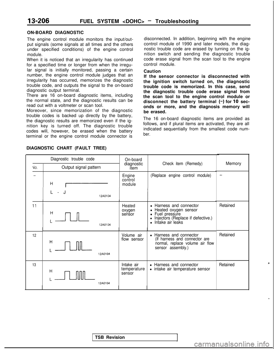
ON-BOARD DIAGNOSTIC
The engine control module monitors the input/out- put signals (some signals at all times and the others
under specified conditions) of the engine control
module.
When it is noticed that an irregularity has continued
for a specified time or longer from when the irregu- lar signal is initially monitored, passing a certain
number, the engine control module judges that an
irregularity has occurred, memorizes the diagnostic
trouble code, and outputs the signal to the on-board diagnostic output terminal.
There are 16 on-board diagnostic items, including
the normal state, and the diagnostic results can be read out with a voltmeter or scan tool.
Moreover, since memorization of the diagnostic
trouble codes is backed up directly by the battery,
the diagnostic results are memorized even if the ig- nition key is turned off. The diagnostic trouble
codes will, however, be erased when the battery
terminal or the engine control module connector is
DIAGNOSTIC CHART (FAULT TREE) disconnected. In addition, beginning with the engine
control module of 1990 and later models, the diag- nostic trouble code are erased by turning on the ig-
nition switch and sending the diagnostic trouble
code erase signal from the scan tool to the engine
control module.
Caution If the sensor connector is disconnected with
the ignition switch turned on, the diagnostic
trouble code is memorized. In this case, send
the diagnostic trouble code erase signal from
the scan tool to the engine control module or disconnect the battery terminal
(-) for 10 sec-
onds or more, and the diagnosis memory will be erased.
The 16 on-board diagnostic items are provided as
follows, and if plural items are activated, they are all indicated sequentially from the smallest code num-
ber. ti0.
Diagnostic trouble code
Output signal pattern
On-boarddiagnostic
itemCheck item (Remedy)
-Engine (Replace engine control module)
control
H Imodule
L-
J
12A0104
Heatedoxygen
sensor
l Harness and connectorl Heated oxygen sensorl Fuel pressurel Injectors (Replace if defective.) 12A0104l Intake air leaks
12
13 12A0104Volume airl Harness and connector
flow sensor(If harness and connector are
normal, replace volume air flow
sensor assembly.)
Intake air
l Harness and connector
temperaturel intake air temperature sensorsensor 12A0104
Memory
Retained
Retained
Retained
TSB Revision
Page 353 of 1273
FUEL SYSTEM
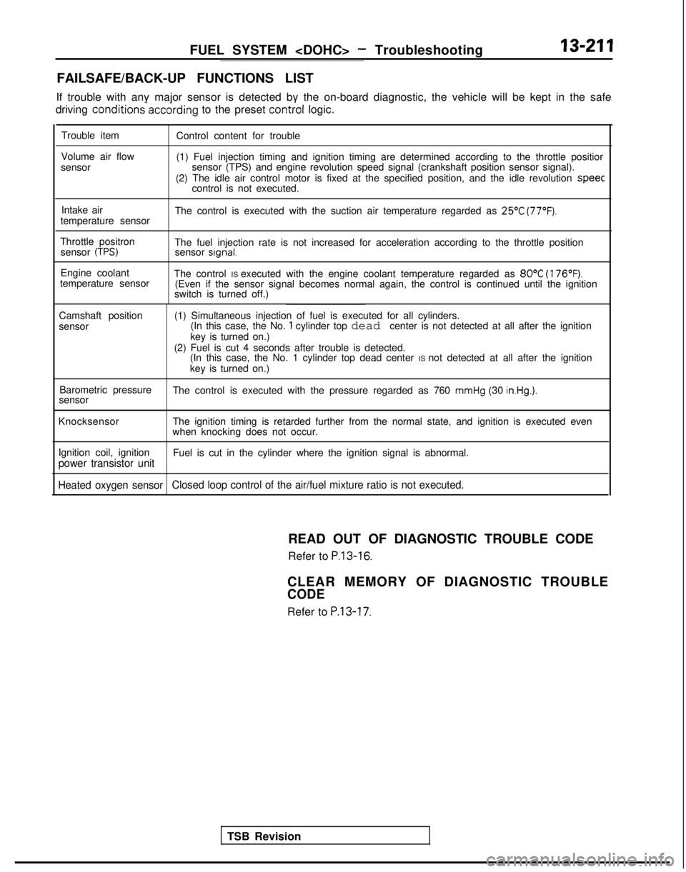
FAILSAFE/BACK-UP FUNCTIONS LIST
If trouble with any major sensor is detected by the on-board diagnostic,\
the vehicle will be kept in the safe
driving conditions-accdrding
to the preset control
logic.
Trouble item
Volume air flow
sensor Control content for trouble
(1) Fuel injection timing and ignition timing are determined according\
to the throttle positior
sensor (TPS) and engine revolution speed signal (crankshaft position \
sensor signal).
(2) The idle air control motor is fixed at the specified position, and\
the idle revolution speec
control is not executed.
Intake air
temperature sensor The control is executed with the suction air temperature regarded as
25’C (77°F).
Throttle positron
sensor (TPS)The fuel injection rate is not increased for acceleration according to t\
he throttle positionsensor signal.
Engine coolant
temperature sensor The control IS executed with the engine coolant temperature regarded as 80°C
(176°F).(Even if the sensor signal becomes normal again, the control is continu\
ed until the ignition
switch is turned off.)
Camshaft position
sensor (1) Simultaneous injection of fuel is executed for all cylinders.
(In this case, the No.
1 cylinder top dead center is not detected at all after the ignition
key is turned on.)
(2) Fuel is cut 4 seconds after trouble is detected. (In this case, the No. 1 cylinder top dead center IS not detected at all after the ignition
key is turned on.)
Barometric pressure
sensor The control is executed with the pressure regarded as 760
mmHg (30 in.Hg.).
Knocksensor
The ignition timing is retarded further from the normal state, and ignit\
ion is executed even
when knocking does not occur.
Ignition coil, ignition
power transistor unitFuel is cut in the cylinder where the ignition signal is abnormal.
Heated oxygen sensor Closed loop control of the air/fuel mixture ratio is not executed.
TSB RevisionREAD OUT OF DIAGNOSTIC TROUBLE CODE
Refer to
P.13-16.
CLEAR MEMORY OF DIAGNOSTIC TROUBLE
CODE
Refer to P.13-17.
Page 360 of 1273
13-218
FUEL SYSTEM
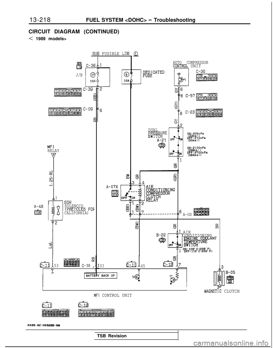
CIRCUIT DIAGRAM (CONTINUED)
< 1989 models>
A-40
I@
aI3IC-36
J/B
r
@
101
MFIRELAY
I
i-l
EGK
x
SOLENOID(VHEICLES FOFCALIFORNIA)
2
r
631
ii!.?
53c-10 ,
V
I FUSIBLE LINl
A-07X r
Q
AUTO COMPRESSORCDNTROL UNIT s
52
218 C-23
G
..2DUAL,\
g;&#RE9~g,'~:yP"
A-21 OFb-‘;oN
~&~f~“‘”
@0ON:2100kPa
(299PS I )OFF:2700kPa(384PSl)
"I
F5
A-OSI
ss65iii
B-22~1 AIR" CONDITIONING
q@
XI ON:lOS'C(228'F2 OFF:115'C(239'k1
0365
YY
-IIMAGNETiC CLUTCHMFI CONTROL UNIT
KX35-AC-H05288-NY
TSB Revision
Page 375 of 1273
FUEL SYSTEM
SUB FUSIBLE LIh
I
A-48
m
;I2Ll
z
ku2
i
I
E
??
is
1
1
EGK
x
SOLENOIDWHEICLES FORCALIFORNIA)
2
E
E-
r
A-07X
El3
4
IK
T
>
si
EFATEDA
AUTO COMPRESSOR
CONTROL UNIT
;E56
A3 ,,4.
:
‘o/
‘12 c-23
6 A-08 : : : ::lIIxB3
1 AIR
1
CONDITIONING
ENGINE COOLANT
I ;E&#$TURE
! 8F~!?8;%!~~&Fk1
IJMAGNETIC CLUTCHMFI CONTROL UNIT
KX35-AC-H03378-NW
TSB Revision