1989 MITSUBISHI GALANT air condition
[x] Cancel search: air conditionPage 457 of 1273
FUEL SYSTEM
On-Vehicle
Inwection of MFI
ComDonents13-315
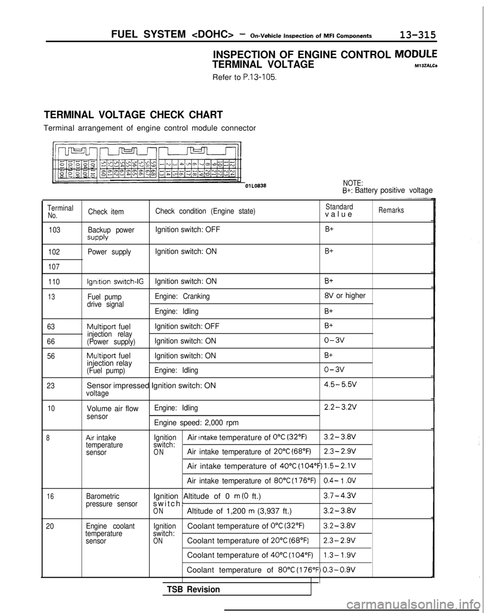
INSPECTION OF ENGINE CONTROL MODULE
TERMINAL VOLTAGEM13zALCa
Refer to P.13-105.
TERMINAL VOLTAGE CHECK CHART
Terminal arrangement of engine control module connector
l!m n-J-J-l-II
NOTE:B+: Battery
positive voltage
TerminalCheck item Check condition (Engine state)Standardvalu
e
Remarks
No.
103
102
107
Backup power
SUPPlY
Power supply
Ignition switch: OFFB+
Ignition switch: ONB+
110
13
63
66 56
23
Ignition switch-IGIgnition switch: ON
Fuel pump Engine: Cranking
drive signal Engine: Idling
Multiport fuel Ignition switch: OFFinjection relay
(Power supply)Ignition switch: ON
Multiport fuel Ignition switch: ON
injection relay
(Fuel pump) Engine: Idling
Sensor impressed Ignition switch: ONvoltage
B+
8V or higher
B+
B+
o-3v
B+
o-3v
4.5- 5.w
10
8
16
20
Volume air flowsensor
Ax intaketemperature
sensor
Barometric
pressure sensor
Engine coolant
temperature sensor Engine: Idling
2.2-3.2V
Engine speed: 2,000 rpm
IgnitionAir Intake temperature of 0°C (32°F)3.2- 3.8V
switch:
ONAir intake temperature of 20°C (68°F)2.3- 2.9V
Air intake temperature of 40°C (104°F) 1.5-2.1V
Air intake temperature of 80°C (176°F)0.4- 1 .OV
Ignition Altitude of 0 m (0 ft.)3.7-4.3v
switch
:
ONAltitude of 1,200 m (3,937 ft.)3.2-3.8V
IgnitionCoolant temperature of 0°C (32’F)3.2-
3.Wswitch:ONCoolant temperature of 20°C (68°F)2.3- 2.9V
Coolant temperature of 40°C (104°F)1.3- 1.9V
Coolant temperature of 80°C (176°F) 0.3-0.9V
TSB Revision
Page 458 of 1273
13-316FUEL SYSTEM
Inspection
of
MFI
Components
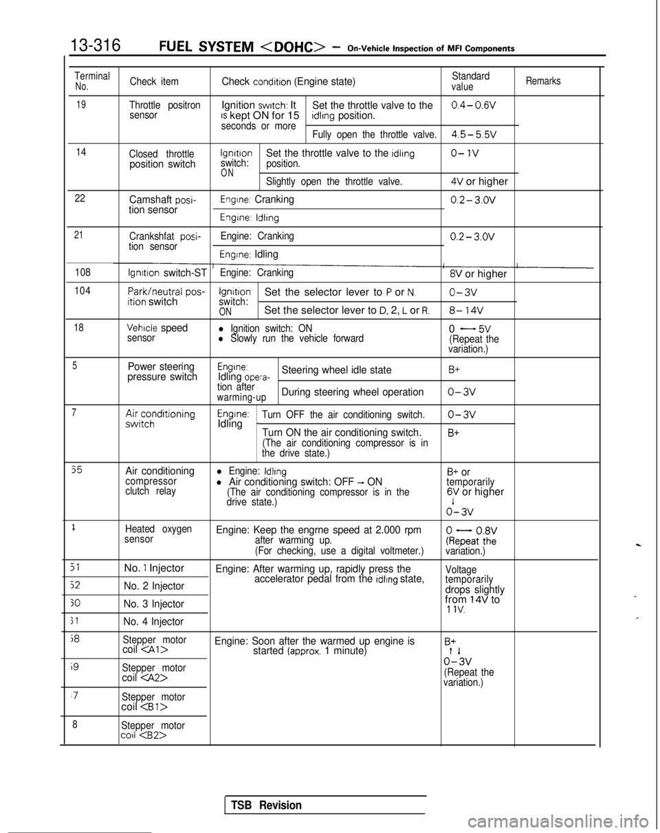
TerminalNo.Check itemCheck condition (Engine state)Standardvalue
Remarks
19Throttle positronIgnition switch: ItSet the throttle valve to the0.4- 0.wsensorIS kept ON for 15seconds or moreidlrng position.
Fully open the throttle valve.4.5- 5.5v
14
Closed throttlelgnrtrono-1vposition switchswitch:Set the throttle valve to the idling
position.
ONSlightly open the throttle valve.4V or higher
22Camshaft posi-tion sensorEngine: Cranking0.2- 3.ov
Engine: ldlrng
21
Crankshfat posi-tion sensor Engine: Cranking0.2- 3.ov
Engine: Idling
108lgnrtion switch-STEngine: Cranking8V or higher
104
Park/neutral
pos-ition switchIgnitionSet the selector lever to P or N.o-3vswitch:ONSet the selector lever to D, 2, L or R.8- 14V
18Vehicle speedl Ignition switch: ON
sensorl Slowly run the vehicle forward0 - 5v(Repeat the
variation.)
5Power steering
pressure switchEngine:Idling opera-Steering wheel idle stateB+
tion afterwarming-upDuring steering wheel operationo-3v
7A&;;;ditioningEngine:Idling _Turn OFF the air conditioning switch.o-3v
Turn ON the air conditioning switch.B+
(The air conditioning compressor is in
the drive state.)
35Air conditioningl Engine: IdlingB+ orcompressor
clutch relayl Air conditioning switch: OFF -, ON(The air conditioning compressor is in the
temporarily
drive state.)6V or higher o’-
3v
1Heated oxygen
sensorEngine: Keep the engrne speed at 2.000 rpmafter warming up.
(For checking, use a digital voltmeter.)ke;atoZivariation.)
51No. 1 InjectorEngine: After warming up, rapidly press the
52No. 2 Injector accelerator pedal from the idlrng state,Voltage
temporarily
drops slightly
30No. 3 Injectorfrom 14V to1 IV.
51No. 4 Injector
j8
Stepper motorcoil
i9
Stepper motor0%
coil
variation.)
‘7Stepper motorcoil
8Stepper motorco11
TSB Revision
Page 476 of 1273
13-334AUTO-CRUISE CONTROL SYSTEM - Troubleshooting
TROUBLESHOOTIN
G
MlJEBDH
The auto-cruise control system performs control functions for
the setting or cancellation of the fixed-speed driving speed bas-
ed upon the data provided by input signals. As a result, when
the auto-cruise control system is canceled, the cause of the
cancellation is memorized in a separate circuit by the ECU,
regardless of whether or not the auto-cruise control system
condition is normal or abnormal, thus providing the ECU with
the on-board diagnostic function by certain fixed patterns, as
well as the function of being able to check whether or not the
ECU’s input switches or sensor are normal. Thus, by effectively
using these function, the time required checking and repair can
be shortened.
NOTE
When the computer (ECU) power supply (ignition switch andmain switch) is switched OF-F, the memorized diagnostic
trouble codes are erased, and so for this reason the power
supply must be left ON until the checking is completed.
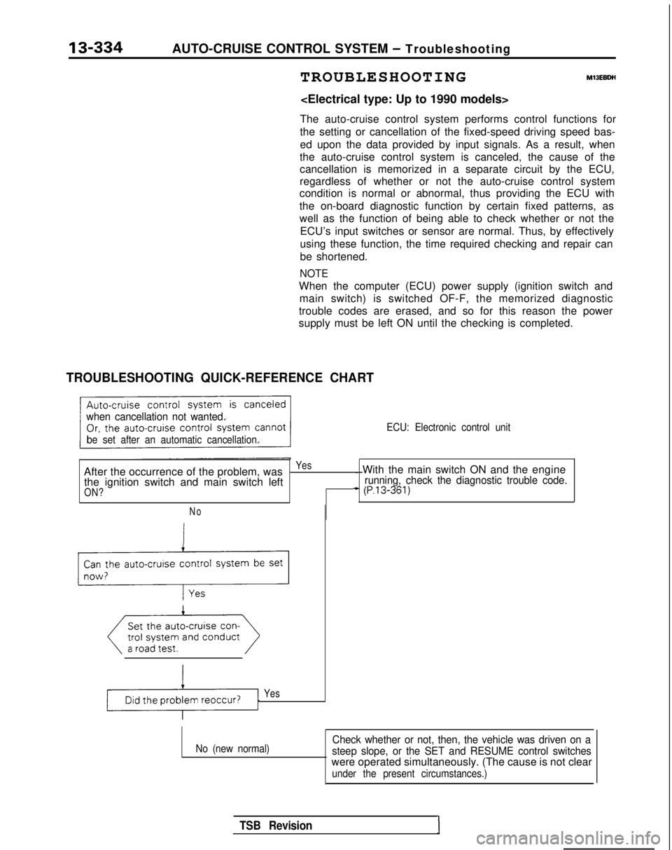
TROUBLESHOOTING QUICK-REFERENCE CHART
when cancellation not wanted.
be set after an automatic cancellation. ECU: Electronic control unit
After the occurrence of the problem, wasYes. With the main switch ON and the engine
the ignition switch and main switch leftrunning, check the diagnostic trouble code.
ON?+ (P.13-361)
No
Can the auto-cruise control system be set
_r-l;
Yes
No (new normal)Check whether or not, then, the vehicle was driven on a
steep slope, or the SET and RESUME control switches
were operated simultaneously. (The cause is not clear
under the present circumstances.)
TSB RevisionI
Page 477 of 1273
AUTO-CRUISE CONTROL SYSTEM - Troubleshooting
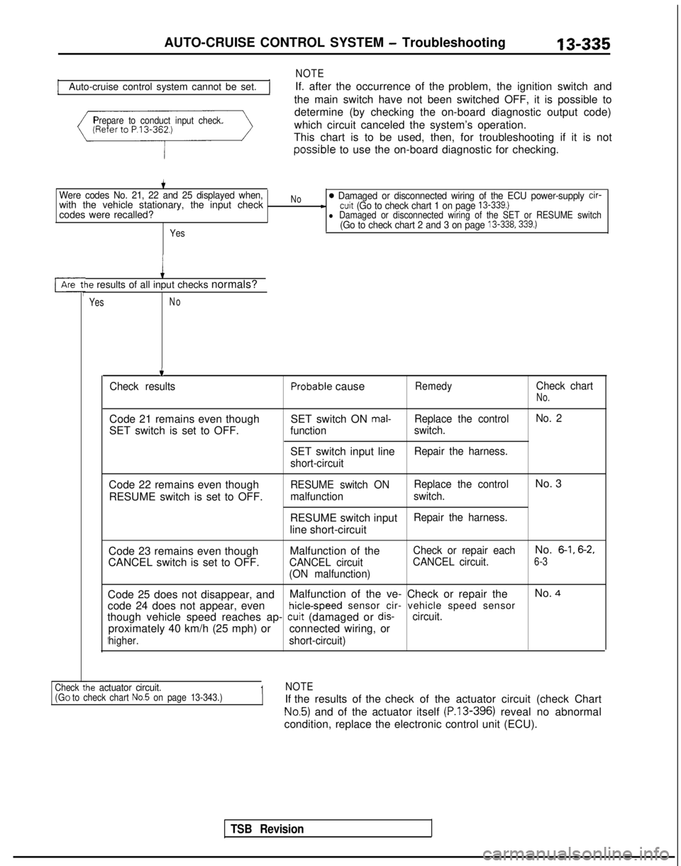
Auto-cruise control system cannot be set.
NOTE
If. after the occurrence of the problem, the ignition switch and
the main switch have not been switched OFF, it is possible to
Prepare to conduct input check.determine (by checking the on-board diagnostic output code)
which circuit canceled the system’s operation.
This chart is to be used, then, for troubleshooting if it is not possible
to use the on-board diagnostic for checking.
Were codes No. 21, 22 and 25 displayed when,with the vehicle stationary, the input check
codes were recalled?
Yes
No0 Damaged or disconnected wiring of the ECU power-supply cir--cuit (Go to check chart 1 on page 13-339.)l Damaged or disconnected wiring of the SET or RESUME switch(Go to check chart 2 and 3 on page 13-338.339.)
le results of all input checks normals?
YesNo
.t
TSB Revision
.
Check resultsProbable causeRemedyCheck chart
No.
Code 21 remains even though
SET switch is set to OFF. SET switch ON mal-Replace the control
No. 2
function switch.
SET switch input lineRepair the harness.
short-circuit
Code 22 remains even though RESUME switch is set to OFF.RESUME switch ON Replace the controlNo. 3
malfunction
switch.
RESUME switch inputRepair the harness.
line short-circuit
Code 23 remains even though
CANCEL switch is set to OFF. Malfunction of the
CANCEL circuit
(ON malfunction) Check or repair each
No. 6-1, 6-2,
CANCEL circuit.6-3
Code 25 does not disappear, and
Malfunction of the ve- Check or repair the No. 4
code 24 does not appear, even hicle-speed
sensor cir- vehicle speed sensor
though vehicle speed reaches ap-
cuit (damaged or dis-circuit.
proximately 40 km/h (25 mph) or connected wiring, or
higher.short-circuit)
ie actuator circuit.1NOTECheck tl(GO to check chart No.5 on page 13-343.)If the results of the check of the actuator circuit (check Chart
No.5) and of the actuator itself (P.13-396) reveal no abnormal
condition, replace the electronic control unit (ECU).
Page 493 of 1273
AUTO-CRUISE CONTROL SYSTEM - Troubleshooting
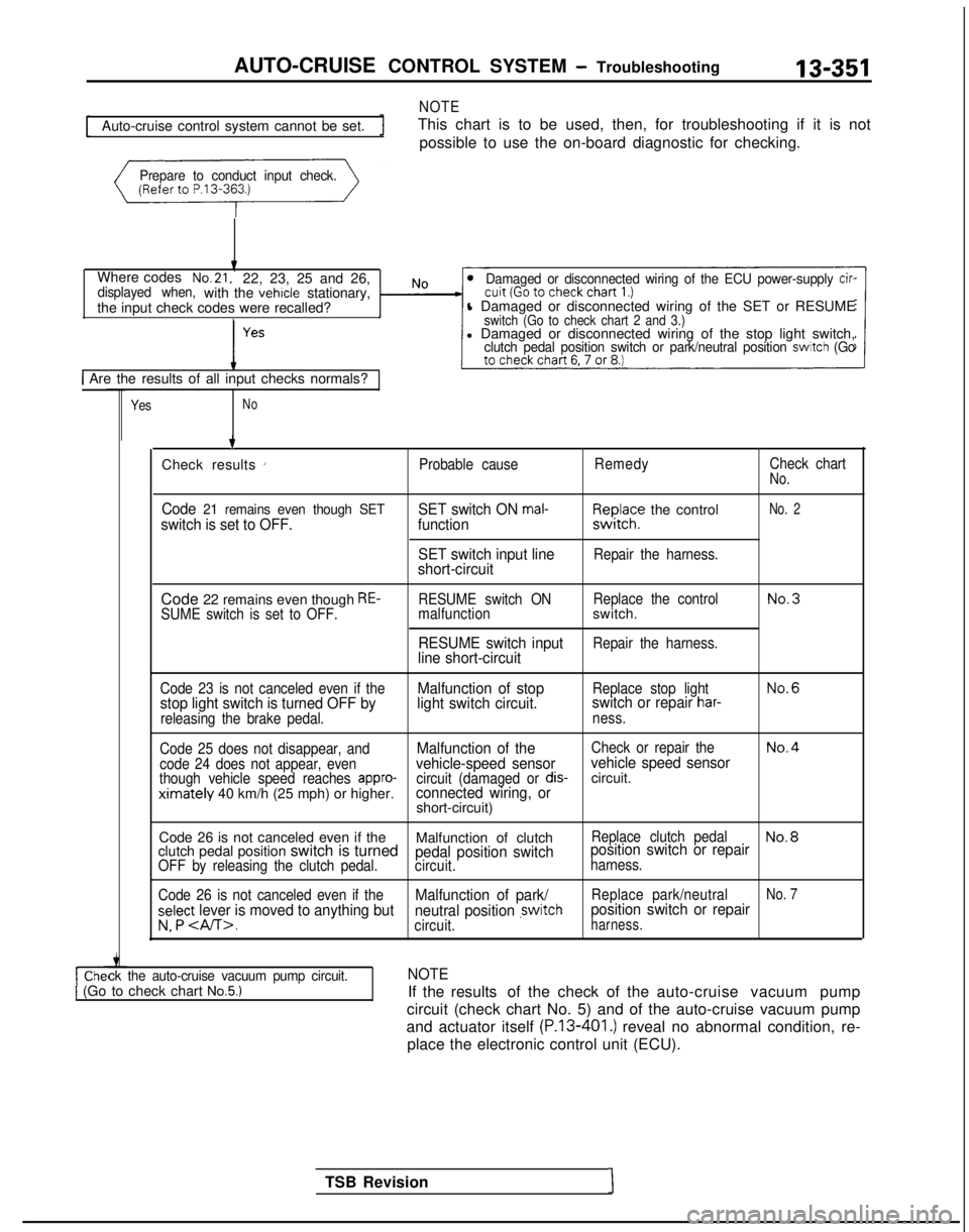
NOTE
13-351
Auto-cruise control system cannot be set.
This chart is to be used, then, for troubleshooting if it is not
possible to use the on-board diagnostic for checking.
Prepare to conduct input check.
Where codesNo.21,22, 23, 25 and 26,displayed when,with the vehicle stationary,
the input check codes were recalled?Damaged or disconnected wiring of the ECU power-supply cir-
l Damaged or disconnected wiring of the SET or RESUMEswitch (Go to check chart 2 and 3.)l Damaged or disconnected wiring of the stop light switch,clutch pedal position switch or park/neutral position switch (Go
1 Are the results of all input checks normals?
YesNo
ck the auto-cruise vacuum pump circuit.1 (Go to check chart No.5.)
TSB Revision1 7
Check results
’Probable cause RemedyCheck chartNo.
Code 21 remains even though SETswitch is set to OFF. SET switch ON mal-function
SET switch input line
short-circuitF,I~JI;? the control
Repair the harness.
No. 2
Code 22 remains even though RE-SUME switch is set to OFF. RESUME switch ON
Replace the controlNo.3malfunctionswitch.
RESUME switch inputRepair the harness.line short-circuit
Code 23 is not canceled even if theMalfunction of stopReplace stop lightNo.6
stop light switch is turned OFF by light switch circuit.switch or repair har-
releasing the brake pedal.
ness.
Code 25 does not disappear, and
Malfunction of theCheck or repair theNo.4
code 24 does not appear, evenvehicle-speed sensor vehicle speed sensorthough vehicle speed reaches appro-circuit (damaged or dis-circuit.ximately 40 km/h (25 mph) or higher.connected wiring, orshort-circuit)
Code 26 is not canceled even if the Malfunction of clutch
Replace clutch pedalNo.8clutch pedal position switch is turnedpedal position switchposition switch or repairOFF by releasing the clutch pedal.
circuit.harness.
Code 26 is not canceled even if the
Malfunction of park/Replace park/neutralNo. 7
select lever is moved to anything but neutral position ,switchposition switch or repair
v. P .circuit.harness.
NOTE
If the results of the check of the auto-cruise vacuum pump
circuit (check chart No. 5) and of the auto-cruise vacuum pump
and actuator itself
(P.13-401.) reveal no abnormal condition, re-
place the electronic control unit (ECU).
Page 540 of 1273
13-398
AUTO-CRUISE CONTROL SYSTEM - Setice Adjustment procedures
03*02.5*
1
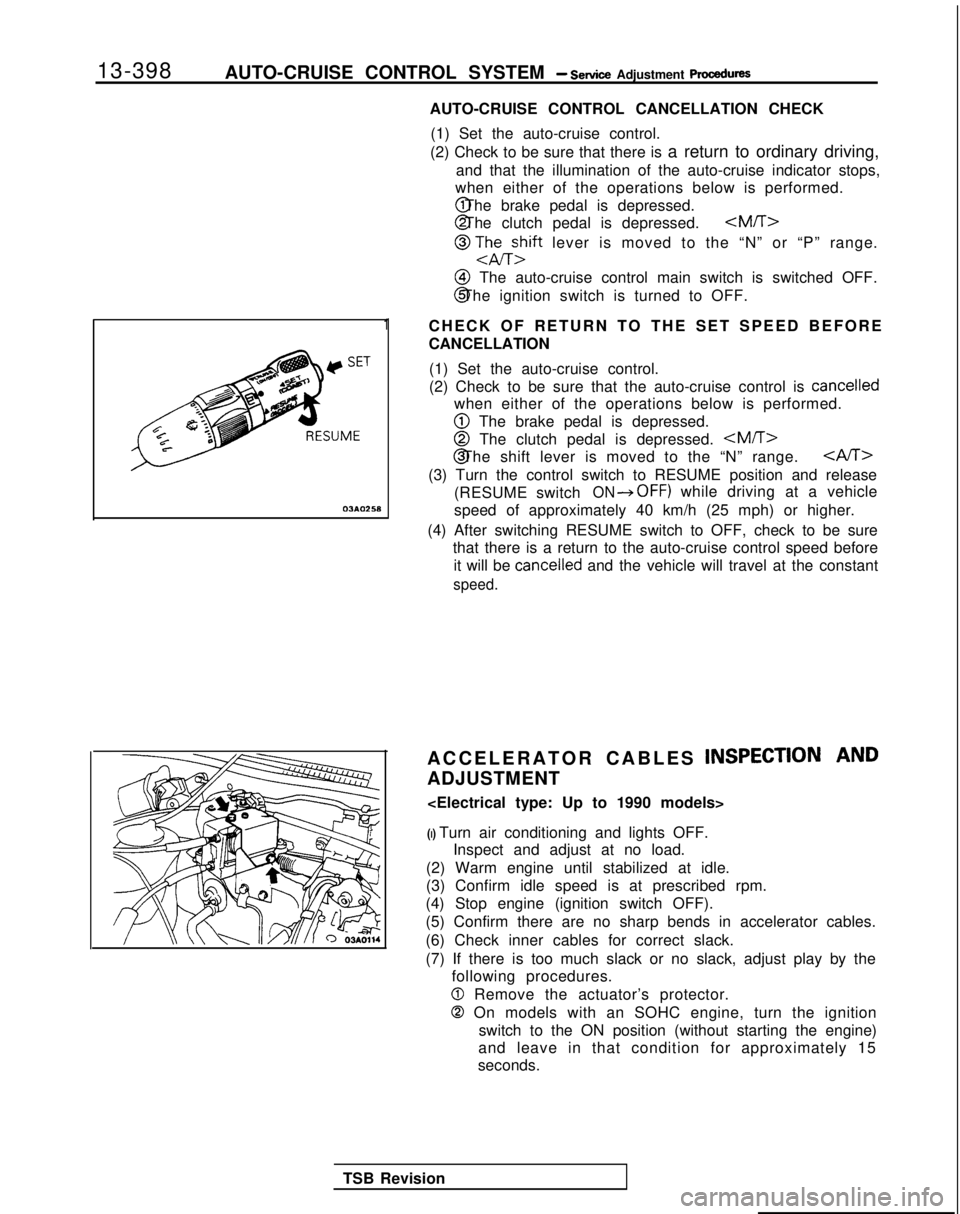
AUTO-CRUISE CONTROL CANCELLATION CHECK
(1) Set the auto-cruise control.
(2) Check to be sure that there is a return to ordinary driving,
and that the illumination of the auto-cruise indicator stops,
when either of the operations below is performed. @ The brake pedal is depressed.
@ The clutch pedal is depressed.
@ TJhEzift lever is moved to the “N” or “P” range.
@I The auto-cruise control main switch is switched OFF.
@ The ignition switch is turned to OFF.
CHECK OF RETURN TO THE SET SPEED BEFORE
CANCELLATION (1) Set the auto-cruise control.
(2) Check to be sure that the auto-cruise control is
cancelled
when either of the operations below is performed.
@ The brake pedal is depressed.
@ The clutch pedal is depressed.
CAST>
(3) Turn the control switch to RESUME position and release
(RESUME switch
ON*OFF) while driving at a vehicle
speed of approximately 40 km/h (25 mph) or higher.
(4) After switching RESUME switch to OFF, check to be sure that there is a return to the auto-cruise control speed before
it will be
cancelled and the vehicle will travel at the constant
speed.
ACCELERATOR CABLES INSPECTION AND
ADJUSTMENT
(I) Turn air conditioning and lights OFF. Inspect and adjust at no load.
(2) Warm engine until stabilized at idle.
(3) Confirm idle speed is at prescribed rpm.
(4) Stop engine (ignition switch OFF).
(5) Confirm there are no sharp bends in accelerator cables.
(6) Check inner cables for correct slack.
(7) If there is too much slack or no slack, adjust play by the following procedures.
0 Remove the actuator’s protector.
0 On models with an SOHC engine, turn the ignition
switch to the ON position (without starting the engine)
and leave in that condition for approximately 15
seconds.
TSB Revision
Page 554 of 1273
14-2
COOLING- Specifications
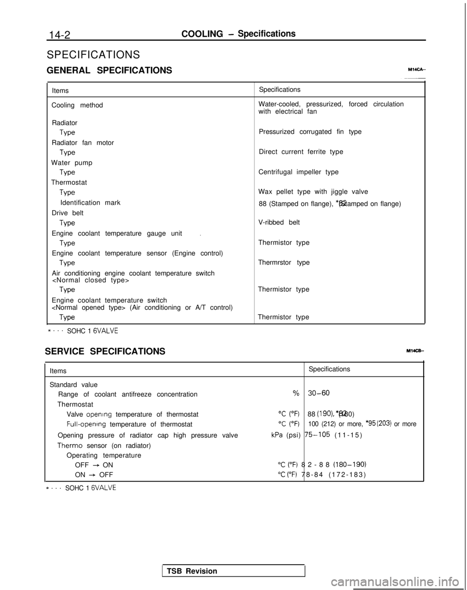
SPECIFICATIONS
GENERAL SPECIFICATIONS
MlICA-
Items
Cooling method Specifications
Water-cooled, pressurized, forced circulation
with electrical fan
Radiator Type
Radiator fan motor Type
Water pump Type
Thermostat Type
Identification mark
Drive belt Type
.Engine coolant temperature gauge unit
Type
Engine coolant temperature sensor (Engine control) Type
Air conditioning engine coolant temperature switch
Engine coolant temperature switch
* . . .SOHC 1 GVALVE
Pressurized corrugated fin type
Direct current ferrite type
Centrifugal impeller type
Wax pellet type with jiggle valve 88 (Stamped on flange), *82 (Stamped on flange)
V-ribbed belt
Thermistor type
Thermrstor type
Thermistor type
Thermistor type
SERVICE SPECIFICATIONS
MlOCB-
Items
Standard value Range of coolant antifreeze concentration
Thermostat Valve opening
temperature of thermostat Full-opening
temperature of thermostat
Opening pressure of radiator cap high pressure valve Therm0
sensor (on radiator)
Operating temperature OFF
+ ON
ON
+ OFF
* . . .SOHC 1 GVALVE
Specifications
% 30-60
“C (“F)88 (IgO), *82 (180)
T (OF)100 (212) or more, *95 (203) or more
kPa (psi) 75-105 (11-15
)
“C (“F) 82-88 (180-190)
“C (“F) 78-84 (172-183
)
TSB Revision
Page 555 of 1273

COOLING- Specifications14-3
Items Specifications
Engine coolant temperature gauge unit ResistanceAt
70°C (158°F)n 104f13.5
Engine coolant temperature sensor (Engine control) ResistanceAt
20°C (68°F)kQ 2.45 f 0.24
At 80°C (176°F)Q 296+32
Air conditioning engine coolant temperature switch
ON
+ OFF operating temperature“C (“F) 112-118 (234-244
)
Engine coolant temperature switch
(Air conditioning or A/T control)
OFF
+ ON operating temperature“C (“F) 100-104 (212-219
)
Limit
Opening pressure of radiator cap high pressure valvekPa (psi) 65 (9.2)
TORQUE SPECIFICATIONS
MWCG-
ItemsNm ft.lbs.
Radiator upper insulator 9-14
7-10
Reserve tank, bracket installation bolt9-1
4
7-10
Thermosensor to radiator35
25
Automatic transaxle oil coole: hose cramp 4-
6
3-4
Automatic transaxle oil cooler hose mounting bolt 3-5
2-4
Water outlet fitting bolts
17-2012-14
Water inlet fitting bolts
IO-157-10
Engine mount insulator nut (large)60-8043-58
Engine mount insulator nut (small)
\ 30-4022-29
Engine mount bracket to engine
50-6536-47
Bracket between engine mount bracket and engine 17-26
12-19
Water pump installation bolt Bolt head mark “4T”
12-15
9-l 1
Bolt head mark “7T”20-2714-20
dater pump pulley bolt8-106-
7
Jamper pulley, crankshaft pulley20-3014-22
Timing belt front upper cover installation bolt
IO-127-
9
Timing belt front lower cover installation bolt
IO-127-
9
Crankshaft
sprocket installation bolt
110-13080-94
Timing belt B tensioner 15-2211-16
Tension pulley bracket for air conditioning
23-2717-20
Automatic tensioner installation bolt20-2714-20
Tensioner pulley installation bolt43-5531-40
Oil level gauge 12-159-l 1
Front exhaust pipe to exhaust manifold
Front exhaust pipe bracket
30-4022-29
Exhaust manifold cover (A), (B)
9-11
Heat protector
TSB Revision