Page 584 of 1273

14-32COOLING -Engine Coolant Temperature Gauge Unit, Engine Coolant
Temperature Sensor and Engine Coolant Temperature Switch
/
Sensor
J
046003
3
04GOO32
9FUO156
---
--I ‘Oi
l
QQQQQQ2cmn99
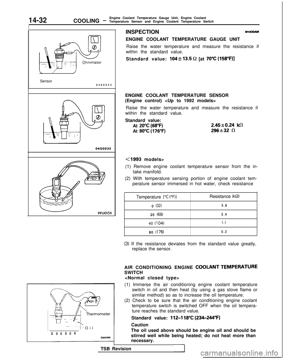
INSPECTIONM14OOAM
ENGINE COOLANT TEMPERATURE GAUGE UNIT
Raise the water temperature and measure the resistance if
within the standard value.
Standard value:
104k13.5 Q [at 70°C (158”F)]
ENGINE COOLANT TEMPERATURE SENSOR
(Engine control)
Raise the water temperature and measure the resistance if
within the standard value.
Standard value:
At
20°C (68°F)
At 80°C (176°F) 2.4520.24
klR
296232 R
<1993 models>
(1) Remove engine coolant temperature sensor from the in- take manifold.
(2) With temperature sensing portion of engine coolant tem- perature sensor immersed in hot water, check resistance
Temperature 1°C (OF)1Resistance (kR)
0 (32)5.8
20 (68)2.4
40
(I
04)1.1
80 (176)0.3
(3) If the resistance deviates from the standard value greatly,
replace the sensor.
AIR CONDITIONING ENGINE
COOLANT TEMPERATURE
SWITCH
(1) Immerse the air conditioning engine coolant temperature switch in oil and then heat (by using a gas stove flame or
similar method) so as to increase the oil temperature.
(2) Check to be sure that the air conditioning engine coolant temperature switch is switched OFF when the oil tempera-ture reaches the standard value.
Standard value:
112-l 18°C (234-244°F)
Caution
The oil used above should be engine oil and should be
stirred well while being heated; do not heat more than
necessary.
TSB Revision
Page 585 of 1273
COOLING -Engine Coolant Temperature Gauge Unit, Engine Coolant
Temperature Sensor and Engine Coolant Temperature Switch14-33
20R0586
ENGINE COOLANT TEMPERATURE SWITCH
(Air conditioning or A/T control)
(1) Remove the engine coolant temperature switch from the
water outlet fitting.
(2) immerse the engine coolant temperature switch in oil and heat by a gas stove or similar method so as to increase the
oil temperature.
(3) Check to be sure that the engine coolant temperature switch is switched ON when the oil temperature reaches
the standard value.
Standard value:
lOO-104% (212-219°F)
CautionUse engine oil for this test; stir it well while heating,
and do not heat more than necessary.
TSB Revision
1
Page 614 of 1273
15-28INTAKE AND EXHAUST - Exhaust Manifold
EXHAUST MANIFOLD
PEMOVAL AND INSTALLATION MlSNA-B
.15 Nm
1 ft.lbs.
7-l
40-50Nm ----‘--A
40-50 Nm /-29-36 ft.lbs.
30-40Nmj’22-29 ft.lbs.
Removal steps
1.Condenser fan motor (Vehicles with airconditioning)
2. Self locking nut
3. Gasket
4*4. Oxygen sensor5. Exhaust manifold cover (A)6. Self locking nut7. Engine hanger8. Exhaust manifold
9. Exhaust manifold gasket
IO. Exhaust manifold cover(B)
TSB Revision1
Page 616 of 1273
15-30 INTAKE AND EXHAUST -Exhaust Manifold
EXHAUST MANIFOLD
REMOVAL AND INSTALLATION
I12-15 Nm9- 11ft.lbs.
27-33 Nm20-23 fklbs.
40 50 Nm29136 ft.lbs.yAS
40-50Nm29- 36ft.lbs.30-40Nm22- 29ft.lbs.12-15 1
30-40Nm9-11 ft.
\
UrnIbs.
MlINA-B
22-29 ft.lbs
Removal steps*b’.
1. Condenser fan motor (Vehicles with air conditioning except AWD A/T)
2. Self locking nut3. Gasket4. Exhaust manifold cover (A)
l *5. Oxygen sensor
6. Self locking nut
7. Engine hanger
8. Exhaust manifold
9. Exhaust manifold gasket
10. Exhaust manifold cover (B)
SERVICE POINTS OF REMOVALMl5NNAH
5. REMOVAL OF OXYGEN SENSOR
Disconnect the connector of the oxygen sensor, and install
the special tool to the oxygen sensor.
Then, using an offset (box-end) wrench, remove the oxygen
sensor.
INSPECTION
Refer to P.15-29i
TSB Revision M15NCA-l
Page 621 of 1273

EMISSION CONTROL
SYSTEMS
CONTENTSr.w?API-
CATALYTIC CONVERTER.....................29
EVAPORATIVE EMISSION CONTROL
SYSTEM..........................................15
Air Conditioning Switch........................21
Component Location...........................15
Evaporative Emission Canister................21
Evaporative Emission Purge Solenoid.......21
Fuel Tank Filler Tube Cap Inspection........21
Fuel Tank Pressure Control Valve............21
Purge Control System Inspection
.................................17
Purge Control System Inspection
>
.......................................
18
Purge Control Valve
..............20
Purge Port Vacuum............................19
Volume Air Flow Sensor, Engine Coolant
Temperature Sensor and Intake Air
Temperature Sensor
...........................21
EXHAUST GAS RECIRCULATION (EGR)
SYSTEM..........................................22
Component Location...........................22
EGR Solenoid ..................28
EGR System Inspection
......25
EGR System Inspection ........25
EGR Temperature Sensor ...28
EGR Valve
......................................27
EGR Valve Control Vacuum..................26
Thermal Vacuum Valve ........27
MIXTURE CONTROL (MFI) SYSTEM. . . . . . . . 29
POSITIVE CRANKCASE VENTILATION
SYSTEM..........................................13
Component Location..........................13
Crankcase Ventilation System Inspection
...14
Positive Crankcase Ventilation (PCV)
Valve Inspection
...............................14
SPECIFICATIONS..................................2
General Specifications...........................2
Sealant............................................2
Service Specifications...........................2
Torque Specifications...........................2
TROUBLESHOOTING.............................3
VACUUM HOSES.................................4
Vacuum Circuit Diagram........................9
Vacuum Hoses Routing.........................4
Page 637 of 1273

EMISSION CONTROL SYSTEMS -Evaporative Emission Control System17-17
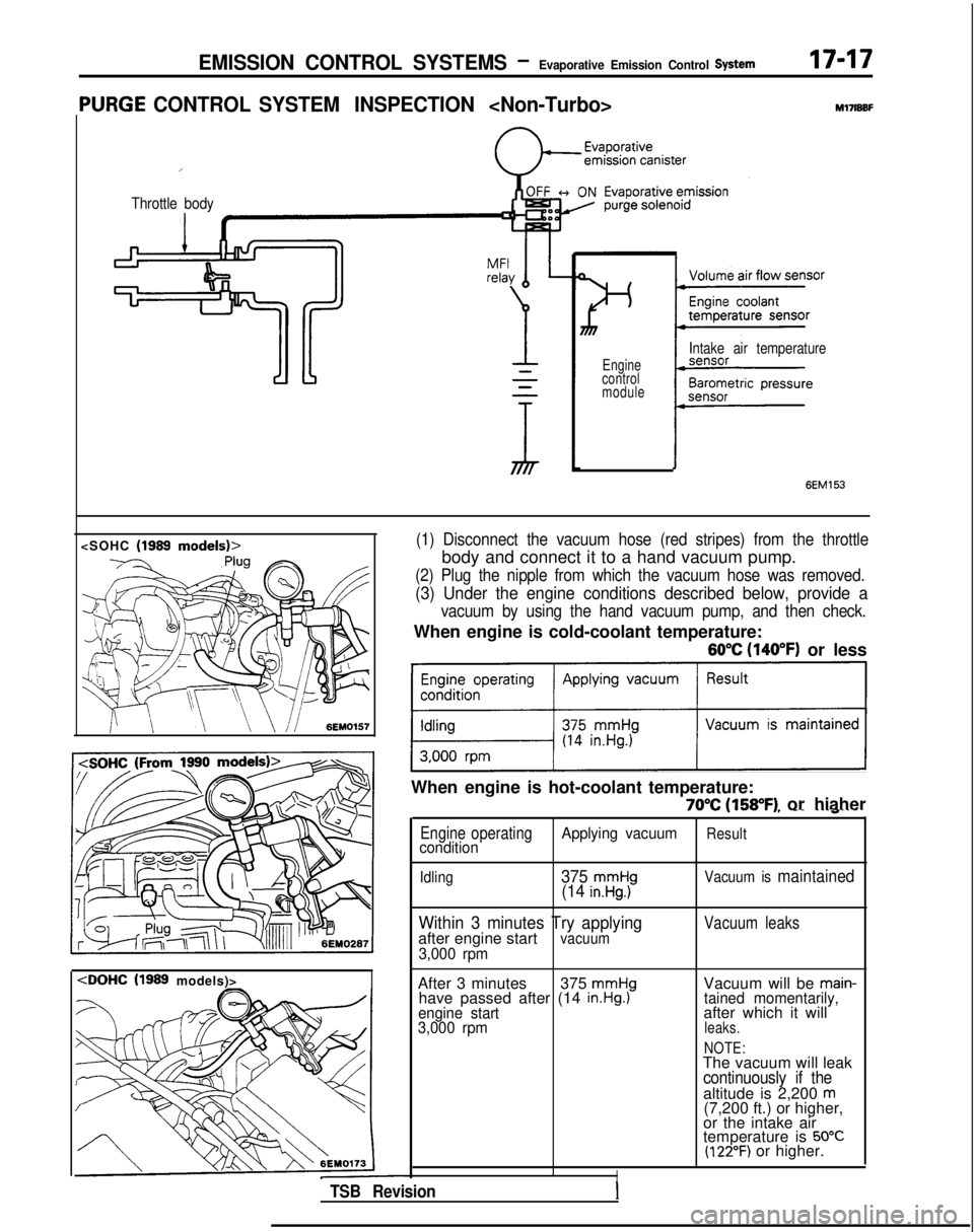
‘URGE CONTROL SYSTEM INSPECTION
I
Throttle body
M17lBBF
Engine
control
module
Intake air temperature
(1999
models)>
6EM153
(1) Disconnect the vacuum hose (red stripes) from the throttle
body and connect it to a hand vacuum pump.
(2) Plug the nipple from which the vacuum hose was removed.
(3) Under the engine conditions described below, provide a
vacuum by using the hand vacuum pump, and then check.
When engine is cold-coolant temperature:
60°C (140°F) or less
~1
When engine is hot-coolant temperature:
70°C (158°F) or hiaher, -- ---~“----
Engine operatingApplying vacuumResultcondition
Idling375 mmHg(14 in.Hg.)Vacuum is maintained
Within 3 minutes Try applyingafter engine startvacuum3,000 rpm
Vacuum leaks
After 3 minutes 375 mmHghave passed after (14 in.Hg.)engine start
3,000 rpm
Vacuum will be main-tained momentarily,after which it willleaks.
NOTE:
The vacuum will leakcontinuously if thealtitude is 2,200 m(7,200 ft.) or higher,
or the intake air
temperature is
50°C(122°F) or higher.
ITSB RevisionI
Page 638 of 1273
EMISSION CONTROL SYSTEMS -Evaporative Emission Control System
PURGE CONTROL SYSTEM INSPECTION M17lBBL
Evaporative
emission canister
Intake air temperature sensorEngine coolant temperature sensor re
Engine control module
I(1)Disconnect the purge air hose from the air intake hose, and
plug the air intake hose. Then, connect the hand vacuum
pump to the purge air hose.
(2) Under the engine conditions shown below, check by
applying vacuum from a hand vacuum pump.
When engine is cold-coolant temperature:
60°C (140°F) or less
Engine operating Applying vacuumResultcondition
1 vacuum is maintained 1ldldl rpm1 gy?r$y)
[ TSB Revision
Page 639 of 1273
EMISSION CONTROL SYSTEMS -Evaporative Emission Control System17-19
When engine is hot-coolant temperature:
70% (158°F) or higher
Engine operating
condition Applying vacuumResult
Idling
Vacuum is maintained
3,000 rpm withinTry applyingthree minutes after vacuumstarting engine
Vacuum leaks
3,000 rpm after
three minutes
have elapsedafter startingengine
375 mmHg(14.8 in.Hg.1Vacuum will be main-tained momentarily,after which it willleaks.
NOTE
The vacuum will leak
continuously if the
altitude is 2,200
m(7,200 ft.) or higher,
or the intake air
temperature is
50°C(122°F) or higher.
PURGE PORT VACUUM MITFVBC
INSPECTION
Non-
Turbo-Up to 1991 models, DOHC Turbo> Engine coolant temperature:
85- 95°C (185- 205°F)
(1) Disconnect the vacuum hose from the throttle body purge hose nipple and connect a hand vacuum pump to the
nipple.
TSB Revision