1989 MITSUBISHI GALANT air condition
[x] Cancel search: air conditionPage 758 of 1273
23-52AUTOMATIC TRANSAXLE - Troubleshooting
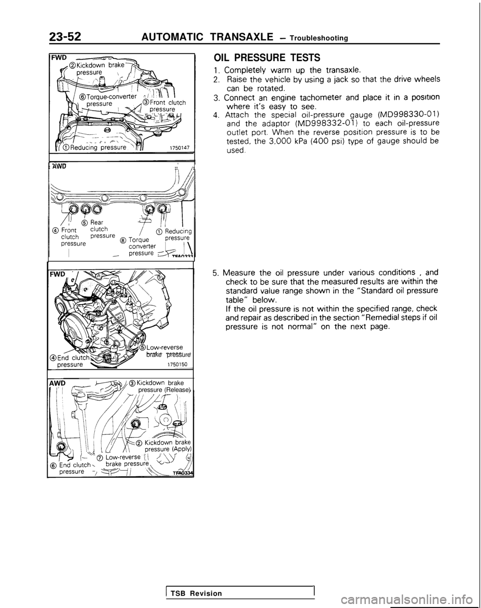
OIL PRESSURE TESTS
1. Completely
warm
up the
transaxle.
2.Raise the
vehicle
by
using
a jack so that the
drive
wheels
can be
rotated.
3.
Connect
an engine
tachometer
and place it
in a positron
where it’s easy
to
see.
4. Attach
the
special oil-pressure
gauge (MD998330-01)
and
the
adaptor
(MD998332-01) to
each oil-pressure
outlet
port. When
the
reverse position pressure is to
be tested,
the
3,000 kPa (400 psi) type
of gauge should be
used.
I AWUII/I
brake pressure
zT?ziw@
Klckdown
brake
pressure (Release)
5. Measure
the
oil pressure
under
various
conditions
, and check
to be sure that the
measured
results
are within the
standard
value
range shown
in the
“Standard
oil pressure
table”
below.
If the
oil pressure
is not
within the
specified
range, check
and repair
as described
in the
section
“Remedial
steps
if oil
pressure
is not
normal”
on the next
page.
1 TSB Revision1
Page 788 of 1273
23-82AUTOMATIC TRANSAXLE - Service Adjustment Procedures
HOTTFA0715
AWD
LT FA0700J
SERVICE ADJUSTMENT PROCEDUR&g
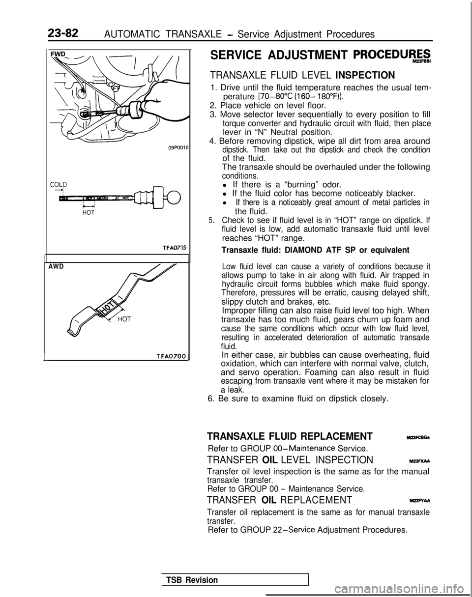
TRANSAXLE FLUID LEVEL INSPECTION
1. Drive until the fluid temperature reaches the usual tem-
perature [70-80°C
(160- 18O”F)I.
2. Place vehicle on level floor.
3. Move selector lever sequentially to every position to fill
torque converter and hydraulic circuit with fluid, then place
lever in “N” Neutral position.
4. Before removing dipstick, wipe all dirt from area around
dipstick. Then take out the dipstick and check the condition
of the fluid.
The transaxle should be overhauled under the following
conditions.
l If there is a “burning” odor.
l If the fluid color has become noticeably blacker.
l
If there is a noticeably great amount of metal particles in
the fluid.
5.Check to see if fluid level is in “HOT” range on dipstick. If
fluid level is low, add automatic transaxle fluid until level
reaches “HOT” range.
Transaxle fluid: DIAMOND ATF SP or equivalent
Low fluid level can cause a variety of conditions because it
allows pump to take in air along with fluid. Air trapped in hydraulic circuit forms bubbles which make fluid spongy.
Therefore, pressures will be erratic, causing delayed shift,
slippy clutch and brakes, etc.
Improper filling can also raise fluid level too high. When
transaxle has too much fluid, gears churn up foam and
cause the same conditions which occur with low fluid level, resulting in accelerated deterioration of automatic transaxle
fluid.
In either case, air bubbles can cause overheating, fluid
oxidation, which can interfere with normal valve, clutch,
and servo operation. Foaming can also result in fluid
escaping from transaxle vent where it may be mistaken for
a leak.
6. Be sure to examine fluid on dipstick closely.
TRANSAXLE FLUID REPLACEMENTM23FcsGa
Refer to GROUP 00-Maintenance
Service.
TRANSFER OIL LEVEL INSPECTIONMm=xM
Transfer oil level inspection is the same as for the manual
transaxle transfer.
Refer to GROUP 00
- Maintenance Service.
TRANSFER OIL REPLACEMENTM23FYAA
Transfer oil replacement is the same as for manual transaxle
transfer.
Refer to GROUP 22-Service
Adjustment Procedures.
TSB Revision
Page 853 of 1273
FRONT AXLE - Drive Shaft
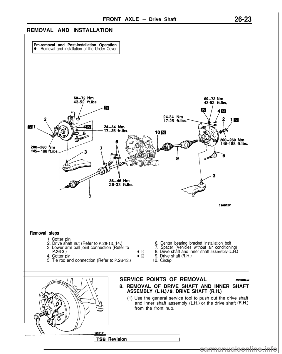
REMOVAL AND INSTALLATION26-23
Pm-removal and Post-installation Operationl Removal and installation of the Under Cover 145-
188 ft.lbs
60-72 Nm
43-52 ftlbs. 60-72
Nm
43-52
ft.lbs.
24-34 Nm 17-25 ft.lbs.
145-188 ft.lbs.
36-k Nm
26-33 ft.lbs.
8
llAOl22
Removal steps
1. Cotter pin
2. Drive shaft nut (Refer to P.26-13, 14.)
3. Lower arm ball joint connection (Refer to
P.26-3.)l *
6. Center bearing bracket installation bolt
7. Spacer (Vehicles without air conditioning)
8. Drive shaft and inner shaft assemblv (L.H.)4. Cotter pinl *9. Drive shaft (R.H.)5. Tie rod end connection (Refer to P.26-13.)10. Circlip
SERVICE POINTS OF REMOVALM26OBAW
8. REMOVAL OF DRIVE SHAFT AND INNER SHAFT
ASSEMBLY (L.H.)/9. DRIVE SHAFT (R.H.)
(1) Use the general service tool to push out the drive shaft
and inner shaft assembly
(L.H.) or the drive shaft (R.H.)
from the front hub.
1 TSB RevisionI
Page 909 of 1273
32-4POWER PLANT MOUNT -Troubleshooting/Engine Mounting
TROUBLESHOOTING
SymptomProbable cause Remedy
Excessive engine wob-
Cracked rubber parts of insulator Replace
ble or vibration (with en-
gine rn normal condition) Insufficiently tightened parts Retighten
Abnormal noise Insufficiently tightened parts Retighten
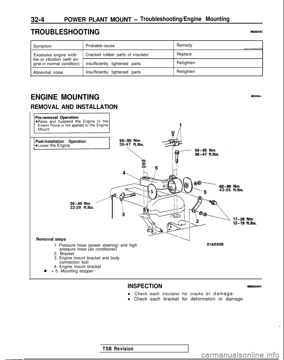
ENGINE MOUNTING
REMOVAL AND INSTALLATION
.
TSB RevisionI
30-40 Nm22-29 ft.lbs.
Removal steps
Post-installation Operation@Lower the Engine
50-65 Nm36-47 ftlbs.
43-56 ft.lbs.
1. Pressure hose (power steering) and high
pressure hose (air conditioner)
2. BracketOIA0306
3. Engine mount bracket and body connection bolt
4. Engine mount bracket
l + 5. Mounting stopper
INSPECTION
l Check each insulator for cracks or damage
.
l Check each bracket for deformation or damage.
Page 950 of 1273
ACTIVE-ELECTRONIC CONTROL SUSPENSION - Troubleshooting 33B-11
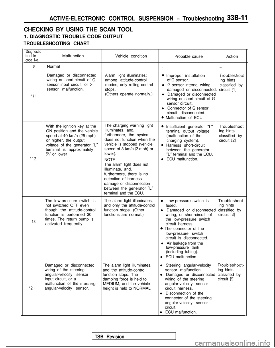
CHECKING BY USING THE SCAN TOOL
1. DIAGNOSTIC TROUBLE CODE OUTPUT
TROUBLESHOOTING CHART
DiagnostictroubleMalfunctionVehicle conditioncode No.Probable causeAction
0Normal---
Damaged or disconnected
Alarm light illuminates;0 Improper installation Troubleshoof
wiring or short-circuit of Gamong attitude-control of G sensor.
sensor input circuit, or Ging hints
modes, only rolling control
sensor malfunction. l
G sensor internal wiring
classified by
stops. damaged or disconnected. circuit
[I]
“11(Others operate normally.)l Damaged or disconnected
wiring or short-circuit of
G
sensor circurt.
l Connector of
G sensor
circuit disconnected.
0 Malfunction of ECU.
W
ith the ignition key at the
The charging warning light
ON position and the vehicle illuminates, and,
0 Insufficient generator “L”Troubleshoot
speed at 40 km/h (25 mph) furthermore, the system terminal output voltage
ing hints
or higher, the output does not function when the (malfunction of the
classified by
charging system). circuit
[2]
voltage of the generator ‘I”vehicle is stopped (vehicle0 Harness short-circuit
terminal is approximately speed of 3 km/h (2 mph) or
5V or lower
lower). between the generator“L” terminal and the ECU.“12
NOTEl ECU malfunction.
The alarm light does not illuminate, and,
furthermore, there is no
detection of harness
damage or disconnection
between the generator “L”
terminal and the ECU.
The low-pressure switch is The alarm light illuminates,
l Low-pressure switch is Troubleshoot
not switched OFF even and only the attitude-control
fused.
though the attitude-control ing hints
function stops. (Other l Damaged or disconnected classified by
function is performed 30 functions are normal.) circuit
131
13times. The return pump is wiring, or short-circuit, of
the low-pressure switch
activated frequently. circuit harness.
0 The connector of the
low-pressure switch
circuit is disconnected.
l Air leakage from the low-pressure tank
(including tubing).
l ECU malfunction.
“21
Damaged or disconnected The alarm light illuminates,l Steering angular-velocity Troubleshoot-
wiring of the steering and the attitude-control sensor malfunction.
angular-velocity sensor ing hints
function stops. The
input circuit, or a l Damaged or disconnected classified by
damping force is held to wiring of the steeringcircuit
191malfunction of the steenng
MEDIUM, and the vehicle
angular-velocity sensor. angular-velocity sensor
height is held to NORMAL circuit harness.
l Disconnection of the connector of the steering
angular-velocity sensor
circuit.
l ECU malfunction.
TSB Revision
Page 953 of 1273
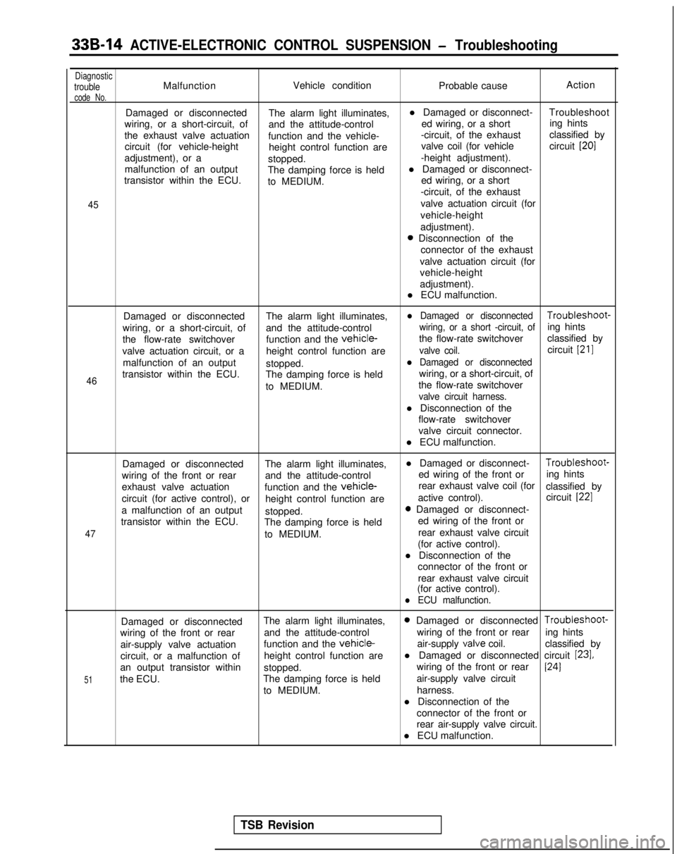
33B-14 ACTIVE-ELECTRONIC CONTROL SUSPENSION - Troubleshooting
DiagnostictroubleMalfunctionVehicle condition
Probable causeAction
code No.
Damaged or disconnected
The alarm light illuminates,l Damaged or disconnect-
Troubleshoot
wiring, or a short-circuit, of and the attitude-control ed wiring, or a shorting hints
the exhaust valve actuation function and the vehicle- -circuit, of the exhaust
classified by
circuit (for vehicle-height height control function are valve coil (for vehicle
circuit
[20]
adjustment), or a
stopped. -height adjustment).
malfunction of an output The damping force is heldl Damaged or disconnect-
transistor within the ECU. to MEDIUM. ed wiring, or a short
-circuit, of the exhaust
45valve actuation circuit (for
vehicle-height
adjustment).
0 Disconnection of the connector of the exhaust
valve actuation circuit (for
vehicle-height
adjustment).
l ECU malfunction.
46
Damaged or disconnected The alarm light illuminates,l Damaged or disconnected Troubleshoot-
wiring, or a short-circuit, of and the attitude-control
wiring, or a short -circuit, ofing hints
the flow-rate switchover function and the
vehicle-the flow-rate switchoverclassified by
valve actuation circuit, or a height control function are
valve coil.circuit [21]
malfunction of an output
stopped.l Damaged or disconnected
transistor within the ECU. The damping force is held wiring, or a short-circuit, of
to MEDIUM. the flow-rate switchover
valve circuit harness.
l Disconnection of the
flow-rate switchover
valve circuit connector.
l ECU malfunction.
47
Damaged or disconnected The alarm light illuminates,l Damaged or disconnect- Troubleshoot-
wiring of the front or rear and the attitude-control ed wiring of the front or
ing hints
exhaust valve actuation function and the
vehicle-rear exhaust valve coil (for
classified by
circuit (for active control), or height control function are active control).
circuit
[22]
a malfunction of an output
stopped.0 Damaged or disconnect-
transistor within the ECU. The damping force is held ed wiring of the front or
to MEDIUM. rear exhaust valve circuit
(for active control).
l Disconnection of the connector of the front or
rear exhaust valve circuit
(for active control).
l ECU malfunction.
51
Damaged or disconnected The alarm light illuminates,0 Damaged or disconnected Troubleshoot-
wiring of the front or rear and the attitude-control wiring of the front or rear
ing hints
air-supply valve actuation function and the
vehicle-air-supply valve
coil. classified by
circuit, or a malfunction of height control function arel Damaged or disconnected circuit
[23],
an output transistor within
stopped. wiring of the front or rear1241
the ECU.
The damping force is held air-supply valve circuit
to MEDIUM. harness.
l Disconnection of the connector of the front or
rear air-supply valve circuit.
l ECU malfunction.
TSB Revision
Page 954 of 1273
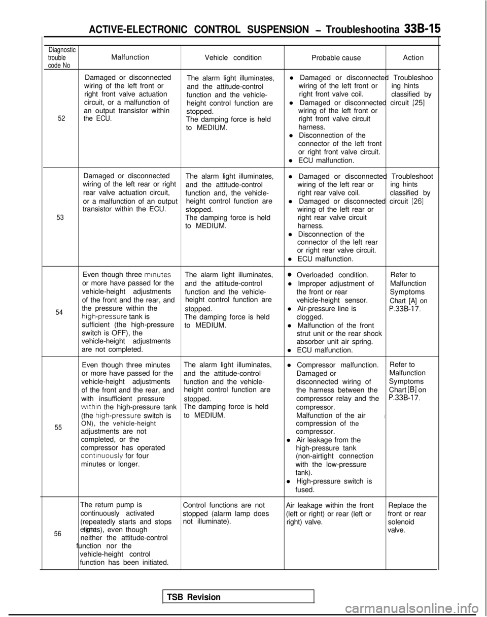
ACTIVE-ELECTRONIC CONTROL SUSPENSION - Troubleshootina 33B-15
Diagnostic
trouble
code NoMalfunction Vehicle condition Probable causeAction
52
Damaged or disconnected
The alarm light illuminates, l Damaged or disconnected Troubleshoo
wiring of the left front or and the attitude-control wiring of the left front or
ing hints
right front valve actuation function and the vehicle- right front valve coil.
classified by
circuit, or a malfunction of height control function arel Damaged or disconnected circuit
[25]an output transistor within
stopped. wiring of the left front orthe ECU.The damping force is held
right front valve circuit
to MEDIUM. harness.
l Disconnection of the connector of the left front
or right front valve circuit.
l ECU malfunction.
53
Damaged or disconnected The alarm light illuminates,
wiring of the left rear or right l Damaged or disconnected Troubleshoot
and the attitude-control wiring of the left rear or
rear valve actuation circuit, ing hints
function and, the vehicle- right rear valve coil.
classified by
or a malfunction of an output height control function are
transistor within the ECU. l Damaged or disconnected circuit
[26]
stopped.
wiring of the left rear or
The damping force is held right rear valve circuit
to MEDIUM.
harness.
l Disconnection of the connector of the left rear
or right rear valve circuit.
l ECU malfunction.
54
55
Even though three mrnutes
The alarm light illuminates,0 Overloaded condition. Refer to
or more have passed for the and the attitude-control l Improper adjustment ofMalfunction
vehicle-height adjustments function and the vehicle- the front or rear
of the front and the rear, and Symptoms
height control function are vehicle-height sensor.
Chart [A] onthe pressure within thestopped.l Air-pressure line isP.33B-17.high-pressure
tank is
The damping force is held
sufficient (the high-pressure clogged.
to MEDIUM. l Malfunction of the front
switch is OFF), the strut unit or the rear shock
vehicle-height adjustments absorber unit air spring.
are not completed. l ECU malfunction.
Even though three minutes The alarm light illuminates,
l Compressor malfunction.Refer to
or more have passed for the and the attitude-control Damaged orMalfunction
vehicle-height adjustments function and the vehicle- disconnected wiring ofSymptoms
of the front and the rear, and height control function are
the harness between theChart
LB1 on
with insufficient pressure stopped. compressor relay and the
P.33B-17.
withtn the high-pressure tankThe damping force is held
compressor.
(the high-pressure
switch isto MEDIUM.
Malfunction of the air
iON), the vehicle-height compression of the
adjustments are not compressor.
completed, or the l Air leakage from the
compressor has operated
continuously for four high-pressure tank
minutes or longer. (non-airtight connection
with the low-pressure
tank).
l High-pressure switch is fused.
The return pump is Control functions are not Air leakage within the frontReplace the
continuously activated stopped (alarm lamp does (left or right) or rear (left orfront or rear
(repeatedly starts and stops not illuminate).
right) valve.solenoid
56erght times), even though
valve.
neither the attitude-control
function nor the
vehicle-height control
function has been initiated.
TSB Revision
Page 955 of 1273
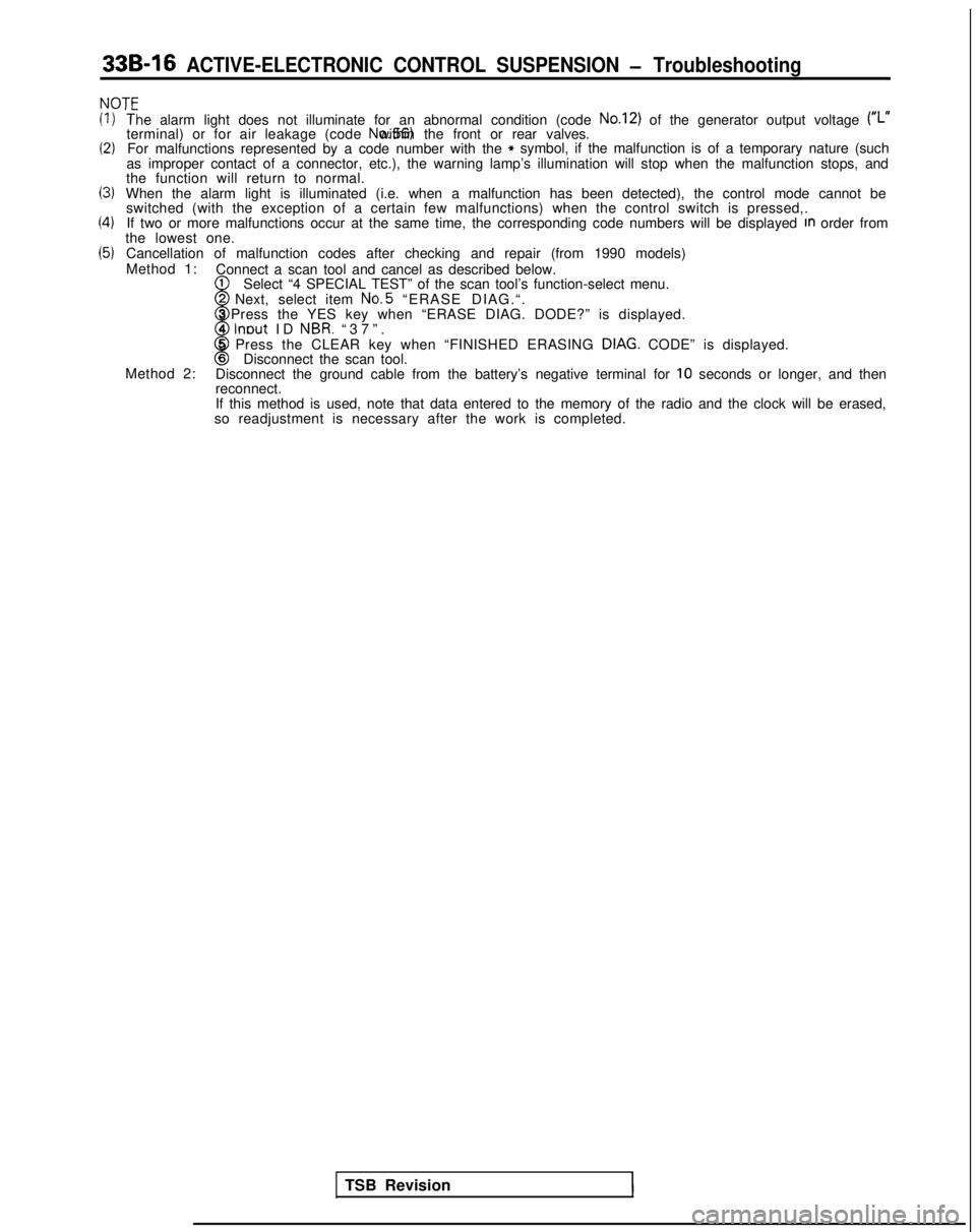
33B-16 ACTIVE-ELECTRONIC CONTROL SUSPENSION - Troubleshooting
NOT’=
(1)
(2)
13)
(4)
(5)
‘T‘he alarm light does not illuminate for an abnormal condition (code No.12) of the generator output voltage (#,.terminal) or for air leakage (code No.56) within the front or rear valves.
For malfunctions represented by a code number with the* symbol, if the malfunction is of a temporary nature (such
as improper contact of a connector, etc.), the warning lamp’s illumi\
nation will stop when the malfunction stops, and
the function will return to normal.
When the alarm light is illuminated (i.e. when a malfunction has been d\
etected), the control mode cannot be switched (with the exception of a certain few malfunctions) when the c\
ontrol switch is pressed,.
If two or more malfunctions occur at the same time, the corresponding co\
de numbers will be displayed
In order from
the lowest one.
Cancellation of malfunction codes after checking and repair (from 1990 \
models)
Method 1: Connect a scan tool and cancel as described below.
1
w
Select “4 SPECIAL TEST” of the scan tool’s function-select menu\
.2 Next, select item No.5
“ERASE DIAG.“.
3 Press the YES key when “ERASE DIAG. DODE?” is displayed.
4
lnout ID NBR. “37”
.
8
5 Press the CLEAR key when “FINISHED ERASING DIAG. CODE” is displayed.6Disconnect the scan tool.
Method 2: Disconnect the ground cable from the battery’s negative terminal for \
10 seconds or longer, and then
reconnect.
If this method is used, note that data entered to the memory of the radi\
o and the clock will be erased,
so readjustment is necessary after the work is completed.
TSB Revision
1