1989 MITSUBISHI GALANT air condition
[x] Cancel search: air conditionPage 640 of 1273
17-20EMISSION CONTROL SYSTEMS -Evaporative Emission Control System
Engine speed (rpm)>
3FU262
E2id>
‘_/- )Engine
speed
(rpm)1 FU446
1 TSB Revision
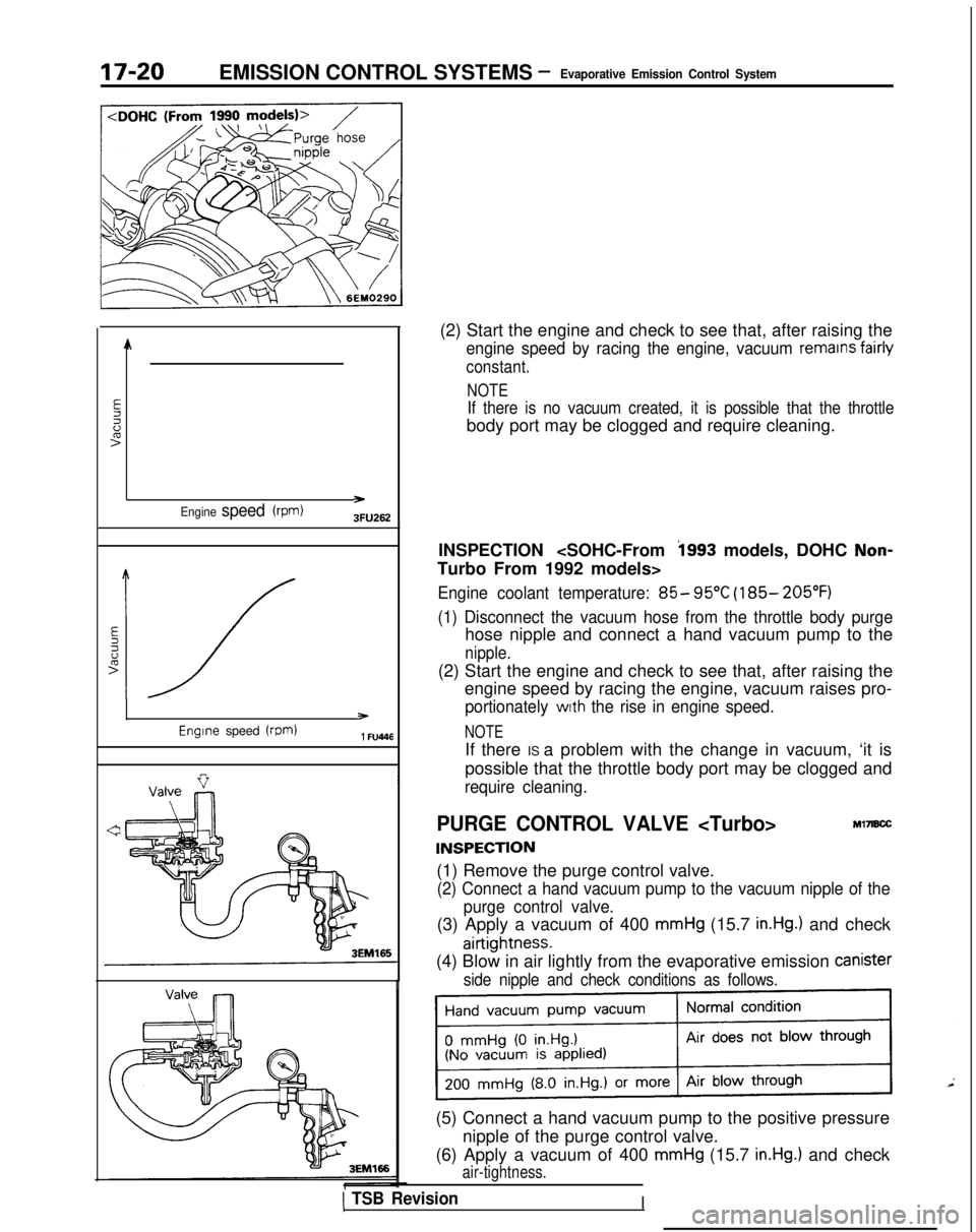
(2) Start the engine and check to see that, after raising the
engine speed by racing the engine, vacuum remains fairly
constant.
NOTE
If there is no vacuum created, it is possible that the throttle
body port may be clogged and require cleaning.
INSPECTION
Turbo From 1992 models>
Engine coolant temperature: 85- 95°C (185- 205°F)
(1) Disconnect the vacuum hose from the throttle body purge
hose nipple and connect a hand vacuum pump to the
nipple.
(2) Start the engine and check to see that, after raising the engine speed by racing the engine, vacuum raises pro-
portionately with the rise in engine speed.
NOTE
If there IS a problem with the change in vacuum, ‘it is
possible that the throttle body port may be clogged and
require cleaning.
PURGE CONTROL VALVE
INSPECTION
Ml7B.X
(1) Remove the purge control valve.
(2) Connect a hand vacuum pump to the vacuum nipple of the
purge control valve.
(3) Apply a vacuum of 400 mmHg (15.7 in.Hg.) and check
airtightness.
(4) Blow in air lightly from the evaporative emission Canister
side nipple and check conditions as follows.
(5) Connect a hand vacuum pump to the positive pressure
nipple of the purge control valve.
(6) Apply a vacuum of 400
mmHg (15.7 in.Hg.) and check
air-tightness.
I
Page 641 of 1273
EMISSION CONTROL SYSTEMS -Evaporative Emission Control System17-21EC1510
6EM137
EVAPORATIVE EMlS$lON
PURGE SOLENOID
INSPECTIONM17lBFD
NOTE
When disconnecting the vacuum hose, make an identification
mark on it so that it can be reconnected to the original posi-
tion.
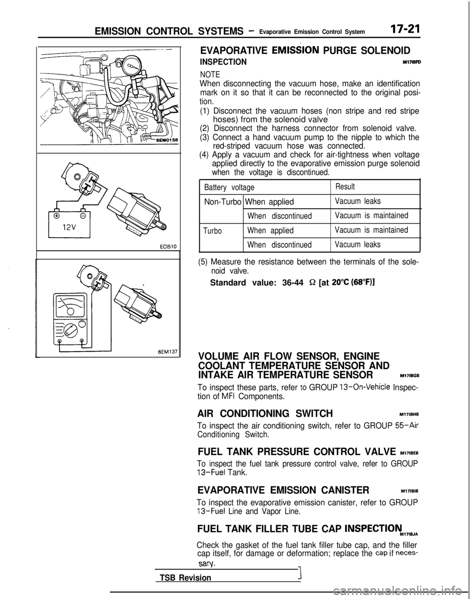
(1) Disconnect the vacuum hoses (non stripe and red stripe
hoses) from the solenoid valve
(2) Disconnect the harness connector from solenoid valve.
(3) Connect a hand vacuum pump to the nipple to which the red-striped vacuum hose was connected.
(4) Apply a vacuum and check for air-tightness when voltage applied directly to the evaporative emission purge solenoid
when the voltage is discontinued.
Battery voltageResult
Non-Turbo When appliedVacuum leaks
When discontinued Vacuum is maintained
TurboWhen appliedVacuum is maintained
When discontinued Vacuum leaks
(5) Measure the resistance between the terminals of the sole-
noid valve.
Standard value: 36-44 Q [at 20°C (68”F)l
VOLUME AIR FLOW SENSOR, ENGINE
COOLANT TEMPERATURE SENSOR AND
INTAKE AIR TEMPERATURE SENSOR
M17IBGB
To inspect these parts, refer to GROUP 13-On-Vehicle Inspec-
tion of
MFI Components.
AIR CONDITIONING SWITCH Ml7IBHB
To inspect the air conditioning switch, refer to GROUP
55-Air
Conditioning Switch.
FUEL TANK PRESSURE CONTROL VALVE MI’IIBEB
To inspect the fuel tank pressure control valve, refer to GROUP
13-Fuel
Tank.
EVAPORATIVE EMISSION CANISTERM17lBlB
To inspect the evaporative emission canister, refer to GROUP
13-Fuel Line and Vapor Line.
FUEL TANK FILLER TUBE CAP INSPECTIONM,7,w~
Check the gasket of the fuel tank filler tube cap, and the filler
cap itself, for damage or deformation; replace the
cap if neces-
sary.
TSB RevisionI
Page 647 of 1273
![MITSUBISHI GALANT 1989 Service Repair Manual EMISSION CONTROL SYSTEMS -Exhaust Gas Recirculation (EGR) System1 T-27
1 <DOHC (From 1990 models)>/]
LEngine speed (rpm)
lFU446
4zJ -6EM159
(2) Start the engine and check to see that, after raising th MITSUBISHI GALANT 1989 Service Repair Manual EMISSION CONTROL SYSTEMS -Exhaust Gas Recirculation (EGR) System1 T-27
1 <DOHC (From 1990 models)>/]
LEngine speed (rpm)
lFU446
4zJ -6EM159
(2) Start the engine and check to see that, after raising th](/manual-img/19/57312/w960_57312-646.png)
EMISSION CONTROL SYSTEMS -Exhaust Gas Recirculation (EGR) System1 T-27
1
LEngine speed (rpm)
lFU446
4zJ -6EM159
(2) Start the engine and check to see that, after raising the
engine speed by racing the engine, vacuum raises prop-
ortionately with the rise in engine speed.
NOTE
if there is a problem with the change in vacuum, it is
possible that the throttle body port may be clogged and
require cleaning.
EGR VALVE
INSPECTION MI’IICKF
(1) Remove the EGR valve and check it for sticking, deposit of
carbon, etc.
If such condition exists, clean with adequate solvent to en-
sure tight valve seat contact.
(2) Connect a hand vacuum pump to the EGR valve.
(3) Apply a vacuum of 500 mmHg (19.6 in.Hg.) and check air
tightness.
(4)Blow in air from one passage of the EGR to check condition
as follows.
INSTALLATION
(1) Install a new gasket and EGR valve, tighten bolts to
specified torque.
Specified tightening torque: 17-26 Nm (12-19 ft.lbs.1
THERMAL VACUUM VALVE
INSPECTION
(1)Disconnect the vacuum hoses from the thermal vacuum
valve, and connect a hand vacuum pump to nipple of the
thermal vacuum valve.
(2) Apply a vacuum and check the air passage through the
thermal vacuum valve.
Page 649 of 1273
I6EM0187
EMISSION CONTROL SYSTEMSExhaust Gas Recirculation (EGR) System/- Catalytic Converter/Air-fuel Ratio Control (MPI) System17-29
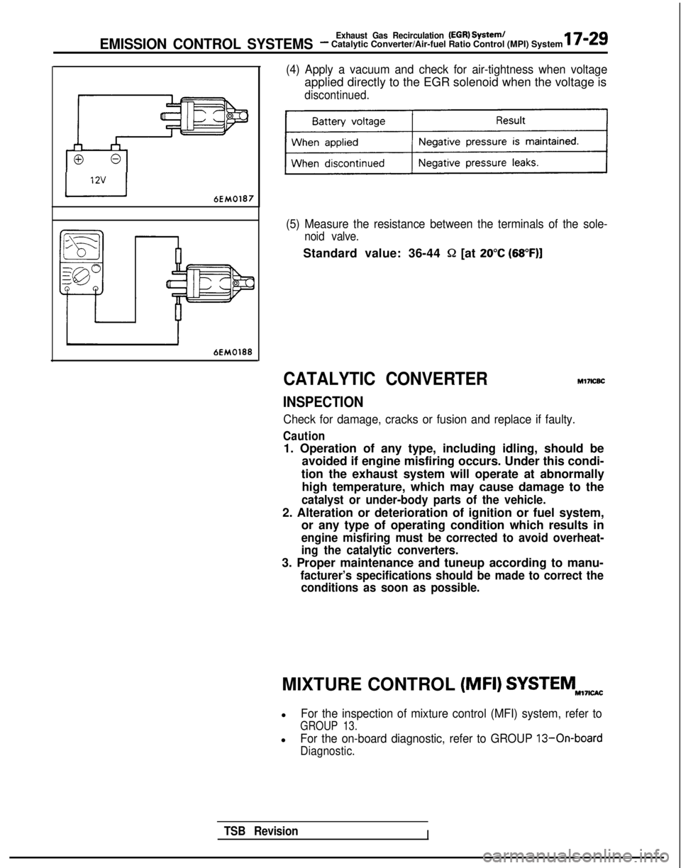
(4) Apply a vacuum and check for air-tightness when voltage
applied directly to the EGR solenoid when the voltage is
discontinued.
(5) Measure the resistance between the terminals of the sole-
noid valve.
Standard value: 36-44 Q [at 20°C (68”F)]
CATALYTIC CONVERTERMl7lcBc
INSPECTION
Check for damage, cracks or fusion and replace if faulty.
Caution
1. Operation of any type, including idling, should be
avoided if engine misfiring occurs. Under this condi-
tion the exhaust system will operate at abnormally high temperature, which may cause damage to the
catalyst or under-body parts of the vehicle.
2. Alteration or deterioration of ignition or fuel system, or any type of operating condition which results in
engine misfiring must be corrected to avoid overheat-
ing the catalytic converters.
3. Proper maintenance and tuneup according to manu-
facturer’s specifications should be made to correct theconditions as soon as possible.
TSB RevisionI
MIXTURE CONTROL (MFI) SYSTEMNI,I,w
lFor the inspection of mixture control (MFI) system, refer to
GROUP 13.
lFor the on-board diagnostic, refer to GROUP 13-On-board
Diagnostic.
Page 728 of 1273
23-22 AUTOMATIC
TRANSAXLE
- Troubleshooting
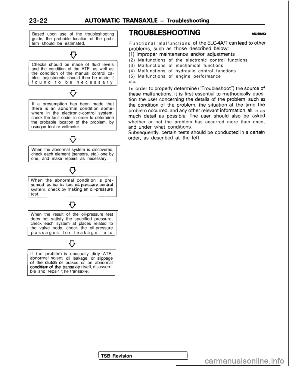
Based upon use of the troubleshooting
guide, the probable location of the prob-
lem should be estimated.
Checks should be made of fluid levels
and the condition of the ATF, as well as
1 found to be necessary
.
the condition of the manual control ca-
bles; adjustments should then be made if
If a presumption has been made that
there is an abnormal condition some-
where in the electronic-control system,
check the fault code, in order to determine
the probable location of the problem, by using a scan tool or voltmeter.
When the abnormal system is discovered,
check each element (sensors, etc.) one by
one, and make repairs as necessary.
When the abnormal condition is pre- sumed to be in the oil-pressure-control
When the result of the oil-pressure test does not satisfy the specified pressure,
1 passages for leakage, etc
.
check each system at places related to
the valve body, check the oil-pressure
If the problem is unusually dirty ATF,
abnormal noises, oil leakage, or slippage
L##t he traniaxle.1
of the clutch or brakes or an abnormal
condition of the transaxle Itself,
disassem-
TROUBLESHOOTING
Functional malfunctions of the ELGWT can lead to other
problems,
such
as those described
below:
(1) Improper
maintenance
and/or
adjustments
(2) Malfunctions of the electronic control functions
(3) Malfunctions of mechanical functions
(4) Malfunctions of hydraulic control functions
(5) Malfunctions of engine performance
etc.
In order
to properly
determine (“Troubleshoot”)
the
source
of
these
malfunctions,
it is first essential
to methodically ques-
tion
the
user
concerning
the details
of the problem,
such as
the
condition of
the
problem,
the
situation at
the
time the
problem
occurred,
and any other relevant
information, all in as much detail
as possible.
The user
should
also be asked
whether or not the problem has occurred more than once,
and under
what conditions. Subsequently,
certain
tests should
be conducted in a certain
order,
as described
at
the
left.
1 TSB Revision
Page 732 of 1273
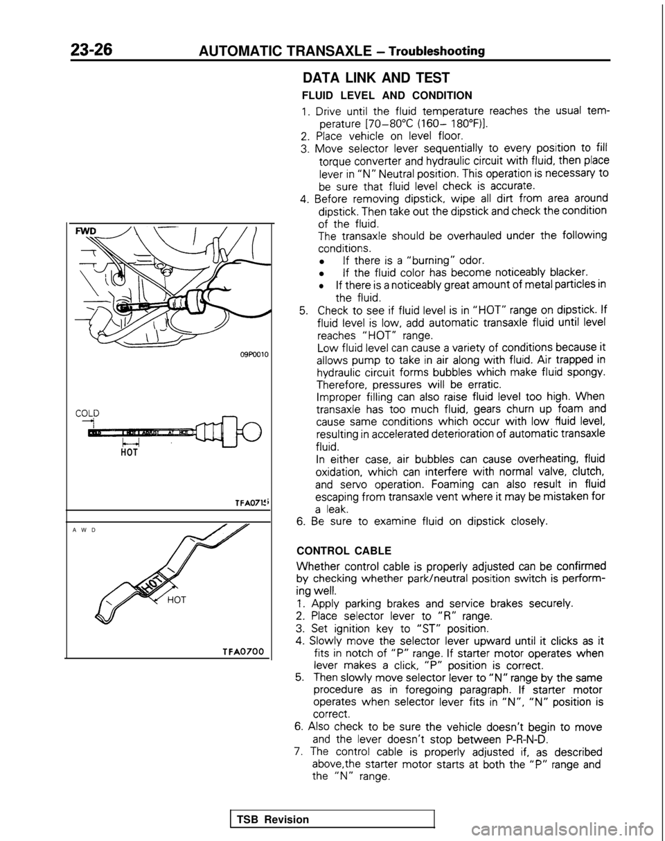
23-26AUTOMATIC TRANSAXLE - Troubleshooting
HOT
TFA0715
AW
D
TFA0700
DATA LINK AND TEST
FLUID LEVEL AND CONDITION
1. Drive until the
fluid
temperature
reaches the
usual tem-
perature
[70-80°C (160- 18O”F)l.
2. Place
vehicle
on level floor.
3. Move
selector
lever sequentially
to
every
position
to fill
torque
converter
and hydraulic circuit
with fluid,
then
place
lever in “N” Neutral position.
This operation is necessary
t0
be sure that fluid
level check is accurate.
4. Before
removing
dipstick,
wipe all dirt from area around
dipstick.
Then take out
the
dipstick
and check the
condition
of the
fluid.
The
transaxle
should be overhauled under the following
conditions.
l If there
is a “burning” odor.
l If the
fluid
color
has become
noticeably
blacker.
lIf there
is a noticeably
great
amount
of metal particles in
the
fluid.
5.Check to
see if fluid
level is in “HOT” range on dipstick.
If
fluid
level is low, add automatic
transaxle
fluid
until level
reaches “HOT” range.
Low
fluid
level can cause a variety of
conditions
because it
allows
pump
to
take
in air along with fluid. Air trapped in
hydraulic circuit
forms
bubbles
which
make fluid
spongy.
Therefore,
pressures
will be erratic. Improper filling
can also raise fluid level too
high. When
transaxle
has too
much fluid,
gears churn up foam and
cause same
conditions
which occur with low fluid
level, resulting
in accelerated deterioration
of
automatic
transaxle
fluid.
In
either
case, air bubbles
can cause overheating,
fluid
oxidation,
which can interfere
with normal valve, clutch,
and
servo
operation.
Foaming can also result
in fluid
escaping
from
transaxle
vent where it
may be mistaken
for
a leak.
6. Be
sure to
examine
fluid
on dipstick
closely.
CONTROL CABLE
Whether control
cable is properly
adjusted
can be confirmed
by
checking
whether park/neutral
position
switch is perform-
ing
well.
1.
Apply
parking brakes and service
brakes securely.
2. Place
selector
lever
to
“R” range.
3. Set ignition
key to
“ST” position.
4.
Slowly
move
the
selector
lever
upward
until it
clicks as it
fits in
notch of “P” range. If starter
motor
operates
when
lever makes a click, “P”
position
is correct.
5.Then slowly
move
selector
lever to “N” range by
the
same
procedure as in foregoing
paragraph. If starter
motor
operates
when selector
lever
fits in ‘IN”, “N” position
is correct.
6.
Also check to be sure the
vehicle
doesn’t
begin to move
and
the
lever
doesn’t
stop
between
P-R-N-D.
7. The control
cable is properly
adjusted if, as described
above,the
starter
motor
starts
at both the
“P” range and the
“N” range.
TSB Revision
Page 740 of 1273
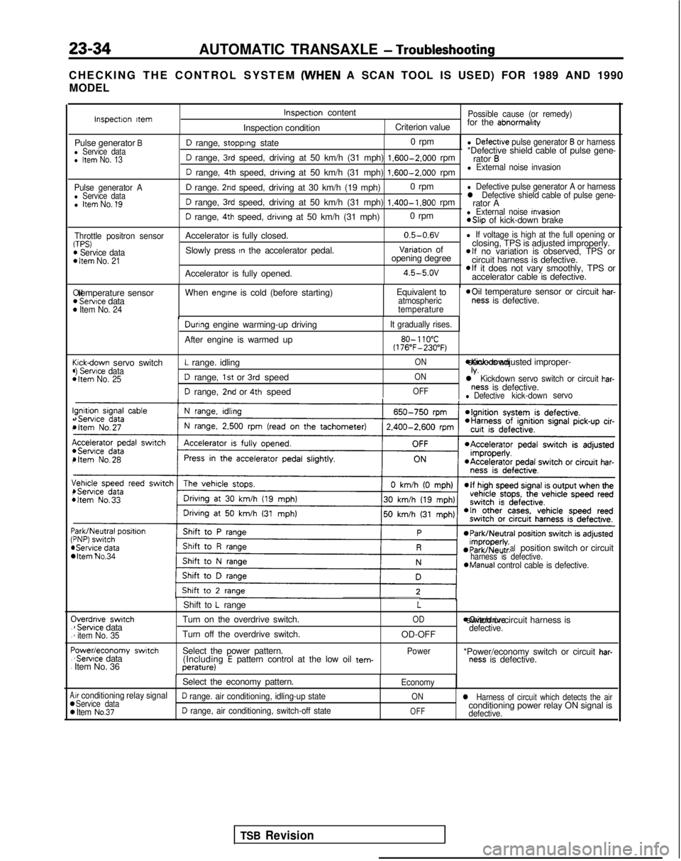
23-34AUTOMATIC TRANSAXLE - Troubleshooting
CHECKING THE CONTROL SYSTEM (WHEN
A SCAN TOOL IS USED) FOR 1989 AND 1990
MODEL
Pulse generator Al Service datal Item No. 1’9
Throttle positron sensorTPS)m Service dataD Item No. 21
I!(
(44
c44
I!.,
I(,
\,4
:44 C
.
.
F.
.
A00
D range, stopprng state 0 rpml Defectrve pulse generator B or harness
D range, 3rd speed, driving at 50 km/h (31 mph) 1.600-2.000
rpm*Defective shield cable of pulse gene-
rator B
D range, 4th speed, drivrng at 50 km/h (31 mph) 1.600-2.000
rpml External noise invasion
D range. 2nd speed, driving at 30 km/h (19 mph) 0 rpml Defective pulse generator A or harness
D range, 3rd speed, driving at 50 km/h (31 mph) 1.400-1.800
rpml Defective shield cable of pulse gene-rator A
D range, 4th speed, drivrng at 50 km/h (31 mph) 0 rpml External noise Invasion *Slip
of kick-down brake
Accelerator is fully closed. 0.5-0.6V
l If voltage is high at the full opening or
Slowly press In the accelerator pedal.Variatron of
closing, TPS is adjusted improperly.
opening degreeelf no variation is observed, TPS or
circuit harness is defective.
Accelerator is fully opened.
4.5-5.ovelf it does not vary smoothly, TPS or
accelerator cable is defective. Xl temperature sensor
) Servtce data) Item No. 24
When engtne is cold (before starting)
Equivalent toatmospheric
temperature *Oil
temperature sensor or circuit har-ness is defective.
cickdown servo switch) Servrce data1 Item No. 25
Durrng engine warming-up driving
After engine is warmed up
L range. idling
D range, 1st or 3rd speed
D range, 2nd or 4th speed
It gradually rises.
80- 110°C(176”F-230°F)
ON *Kick-down servo IS adjusted improper-
ONIV.l Kickdown servo switch or circuit har-
OFFness is defective.l Defectivekick-down
servo
bItem No.34 alposition switch or circuitharness is defective.*Manual
control cable is defective.
Iverdnve switch1 Servrce data1 item No. 35
‘owedeconomy swatch‘Servrce data
Item No. 36 Shift to
L range
Turn on the overdrive switch.
Turn off the overdrive switch.
Select the power pattern. (Including
E pattern control at the low oil tem-perature)
L
OD
OD-OFF
Power moverdrive switch or circuit harness is
defective.
*Power/economy switch or circuit har-ness is defective.
Select the economy pattern.
Economy
.ir conditioning relay signalService dataD range. air conditioning, idling-up stateONl Harness of circuit which detects the air
Item No.37D range, air conditioning, switch-off stateOFFconditioning power relay ON signal isdefective.
Inspectron ttemInspectron content
Inspection conditionPossible cause (or remedy)
Criterion value for the abnormalrty
Pulse generator Bl Service datal Item No. 13
TSB Revision
Page 741 of 1273
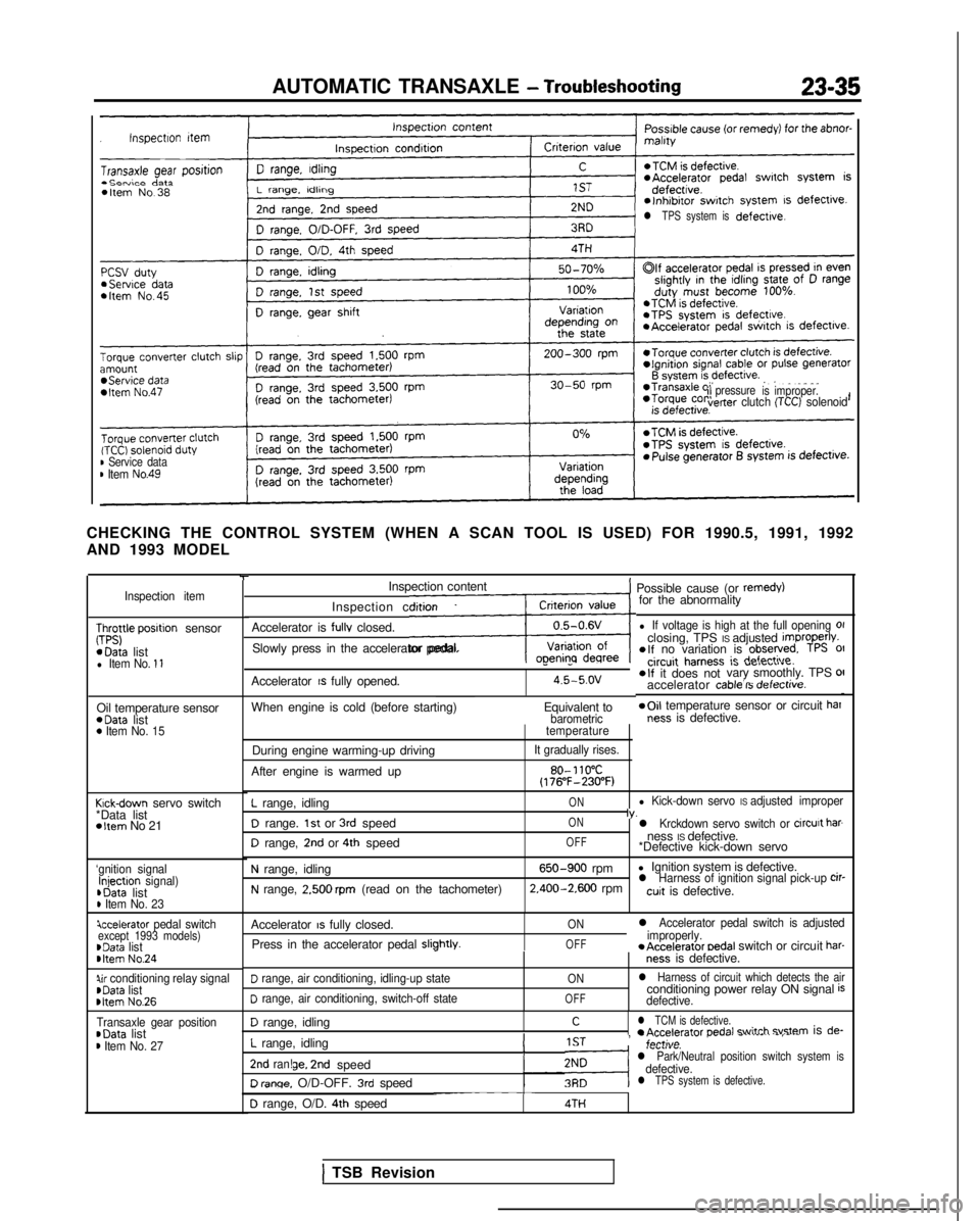
AUTOMATIC TRANSAXLE - Troubleshooting23-35
l TPS system isdefective.
ilpressure
is improper.verter clutch (TCC) solenoid
B Service datam Item No.49
CHECKING THE CONTROL SYSTEM (WHEN A SCAN TOOL IS USED) FOR 1990.5, 199\
1, 1992
AND 1993 MODEL
Inspection item
;;;yle posrtion sensor *Data
list
l Item No. 11
Oil temperature sensor *Data
list
0 Item No. 15
Krck-down servo switch
*Data list
*Item No 21
‘gnition signalInjectron signal) ,Data
list
D Item No. 23
iccelerator pedal switchexcept 1993 models)~Data listbItem No.24
Qr conditioning relay signalrData list rltem
No.26
Transaxle gear position~Data listm Item No. 27
-rInspection content
Inspection condition
Accelerator is
fullv closed.
LSlowly press in the accelerator pedal.
1 Possible cause (or remedy)for the abnormality
l If voltage is high at the full opening 01closing, TPS IS adjusted improperlv.elf no variation is observed. TPS 01
Accelerator IS fully opened.
--circuit harness ic r(afndi
O,a “ClrULIIu.
4.5-5.ov*If it does not vary smoothly. TPS OII- .-d-L__.:__accelerator cable IS oerectrve.
When engine is cold (before starting)
Equivalent to*Oil temperature sensor or circuit barbarometricness is defective.
During engine warming-up driving
After engine is warmed uptemperature
It gradually rises.
80- 110°C(176”F-230°F)
L range, idling
D range. 1st or 3rd speed
D range, 2nd or 4th speed
ON
ON
OFFl Kick-down servo IS adjusted improperIv.l Krckdown servo switch or circurt barness IS defective.
*Defective kick-down servo
N range, idling
N range, 2.500 rpm (read on the tachometer)
650-900 rpm l Ignition system is defective. 2.400-2.600
rpml Harness of ignition signal pick-up cir-cuit is defective.
Accelerator
IS fully closed.
Press in the accelerator pedal
sliphtlv.I
ON
OFF
l Accelerator pedal switch is adjusted
improperly. *Accelerator
oedal switch or circuit har-ness is defective.
D range, air conditioning, idling-up state
D range, air conditioning, switch-off state
ON
OFF
l Harness of circuit which detects the airconditioning power relay ON signal isdefective.
D range, idling
L range, idling
Cl TCM is defective.r A~d~r~tnr nednl +witch svstem is de-
!IST, -;,,tl;;..- r..--. -.-.--..
-,---,.,.,.,.v.l Park/Neutral position switch system isdefective.2nd ran!ge. 2nd speed
D renqe. O/D-OFF. 3rd speedl TPS system is defective.-~~~~~D range, O/D. 4th speed4TH
1 TSB Revision