1989 MITSUBISHI GALANT air condition
[x] Cancel search: air conditionPage 1070 of 1273
Solenoid Valve and
ACTIVE-ELECTRONIC CONTROL SUSPENSION - Dryer33B-131
3
F
‘G
\
12A0371
>
Rearpressure
sensor
l------i-l
12AO294
TSB Revision
-n
Coat withsoap-and-water
solution.
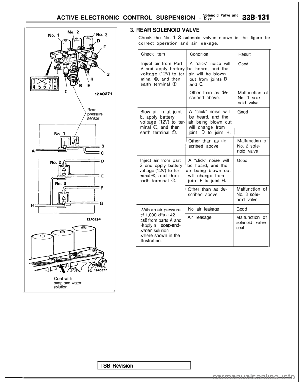
3. REAR SOLENOID VALVE
Check the No.
l-3 solenoid valves shown in the figure for
correct operation and air leakage.
Check item ConditionResult
Inject air from Part A “click” noise will
GoodA and apply battery be heard, and the
voltage
(12V) to ter- air will be blown
minal
0, and then out from joints B
earth terminal 0.and C.
Other than as de-Malfunction of
scribed above. No. 1 sole-
noid valve
Blow air in at joint A “click” noise will
Good
E, apply batterybe heard, and the
voltage
(12V) to ter- air being blown out
minal
0, and then will change from
earth terminal
0.joint D to joint H. /
: Other than as de-Malfunction of
I scribed above No. 2 sole-
noid valve
Inject air from part A “click” noise will
Good
3 and apply battery i be heard, and the doltage
(12V) to ter- 1 air being blown out
ninal @, and then will change from
sarth terminal 0.joint F to joint H.
I Other than as de-Malfunction of
scribed above. No. 3 sole-
noid valve
i/Vith an air pressureNo air leakageGood
of 1,000 kPa (142
xi) from parts A and Air leakage
Malfunction of -l, apply a
soap-and-solenoid valve
Nater
solution seal Nhere
shown in the
Ilustration.
Page 1153 of 1273
![MITSUBISHI GALANT 1989 Service Repair Manual 35-32SERVICE BRAKES - Anti-lock Braking System Troubleshooting
E-5When diagnostic trouble code “51 VALVE RLY” is displayed
[Explanation]
When the ignition switch is turned ON, the ABSnormal. In ad MITSUBISHI GALANT 1989 Service Repair Manual 35-32SERVICE BRAKES - Anti-lock Braking System Troubleshooting
E-5When diagnostic trouble code “51 VALVE RLY” is displayed
[Explanation]
When the ignition switch is turned ON, the ABSnormal. In ad](/manual-img/19/57312/w960_57312-1152.png)
35-32SERVICE BRAKES - Anti-lock Braking System Troubleshooting
E-5When diagnostic trouble code “51 VALVE RLY” is displayed
[Explanation]
When the ignition switch is turned ON, the ABSnormal. In addition, normally it monitors whether or
ECU switches the valve relay OFF and ON for annot there is power in the valve power monitor line
initial check, compares the voltage of the signal tosince the valve relay is normally ON. Then, if the
the valve relay and valve power monitor line voltage supply of power to the valve power monitor line is
to check whether the valv
e
relay operation is interrupted, this diagnostic trouble code will output.
IGNITIONMAIN FUSIBLESWITCHLINK @ (IGl)
1440679\/
I
When the valve relay is
checked, are the following
conditions found?
No.85-No.86:resistance
value 60-120 QNo. 30-No. 87a: continuityNo.30-No.87: No continui-
t
y
When battery voltage is ap-
plied between terminalsNo. 86 and No.85
grounded.
No.30-No.87: continuityNo.30-No.87a: no continui-
t
y
Yes
the valve relay and
remove the HU connec-
>
NoValve relay malfunction
I
Replace valve relay. I
With the ignition key “ON”, does the voltage between
No ~
HU power harness wire is
broken?,-
the connector terminal No.12 and ground indicate bat-
tery voltage?I
Repair harness.
YesI
Connect the HU harness
and remove the ECUcon-nector.>
Does resistance betweenNo c Malfunction of harness
body connector terminal between HU and ECU No.2
and terminal No.27
in-
dicate
60-120 ohm?I
I Yes
TSB Revision
Replace ABS ECU.I
Page 1172 of 1273
![MITSUBISHI GALANT 1989 Service Repair Manual SERVICE BRAKES - Anti-lock Braking System Troubleshooting35-51
E-5When diagnostic trouble code “51 VALVE RLY” is displayed
[Explanation]
When the ignition switch is turned ON, the ABS
ECU switches MITSUBISHI GALANT 1989 Service Repair Manual SERVICE BRAKES - Anti-lock Braking System Troubleshooting35-51
E-5When diagnostic trouble code “51 VALVE RLY” is displayed
[Explanation]
When the ignition switch is turned ON, the ABS
ECU switches](/manual-img/19/57312/w960_57312-1171.png)
SERVICE BRAKES - Anti-lock Braking System Troubleshooting35-51
E-5When diagnostic trouble code “51 VALVE RLY” is displayed
[Explanation]
When the ignition switch is turned ON, the ABS
ECU switches the valve relay OFF and ON for an
initial check, compares the voltage of the signal to
the valve relay and valve power monitor line voltage
to check whether the valverelay operationis
normal. In addition, normally it monitors whether or
not there is power in the valve power monitor line
since the valve relay is normally ON. Then, if the
supply of power to the valve power monitor line is
interrupted, this diagnostic trouble code will output.
MAIN FUSIBLE$tW&N
LINK @I(IGl)
gEli!z$; lf*x**
IT
510
IU-412 &-,8
ABS ECU
: Non-Turbo . Turbo: Non-Turbo
When the valve relay i
s
checked, are the following
conditions found?No. 85-No. 86:resistance
value 60-120 52No.30-No.87a: continuity
No. 30-No. 87: No continui-
When battery voltage is ap- plied between terminals
No. 86 and No. 85 grounded.
No.30-No.87: continuity
No. 30-No. 87a: no continui-
t
y
remove the HU connec-
\/
I With
the
ignition key “ON”
,
No c HU power harness wire is
does the voltage betweenbroken?the connector terminal No.
12 and ground indicate bat- tery voltage? I
IRepair harness.
YesIIIbI\I
Does resistance between
body connector termina
l
No. 2 and terminal No. 27 in-
dicate
60-120 ohm?
IYes
Is there continuity between
body connector terminal No.
22 and ground? Repair harness.
ABS ECU malfunction Replace ABS ECU.
1 TSB Revision1
Page 1175 of 1273
35-54SERVICE BRAKES - Service Adjustment Procedures
F14519
14UOO61
When engine isstopped
No good
0
w
\/‘14UOO62z;redengine
is
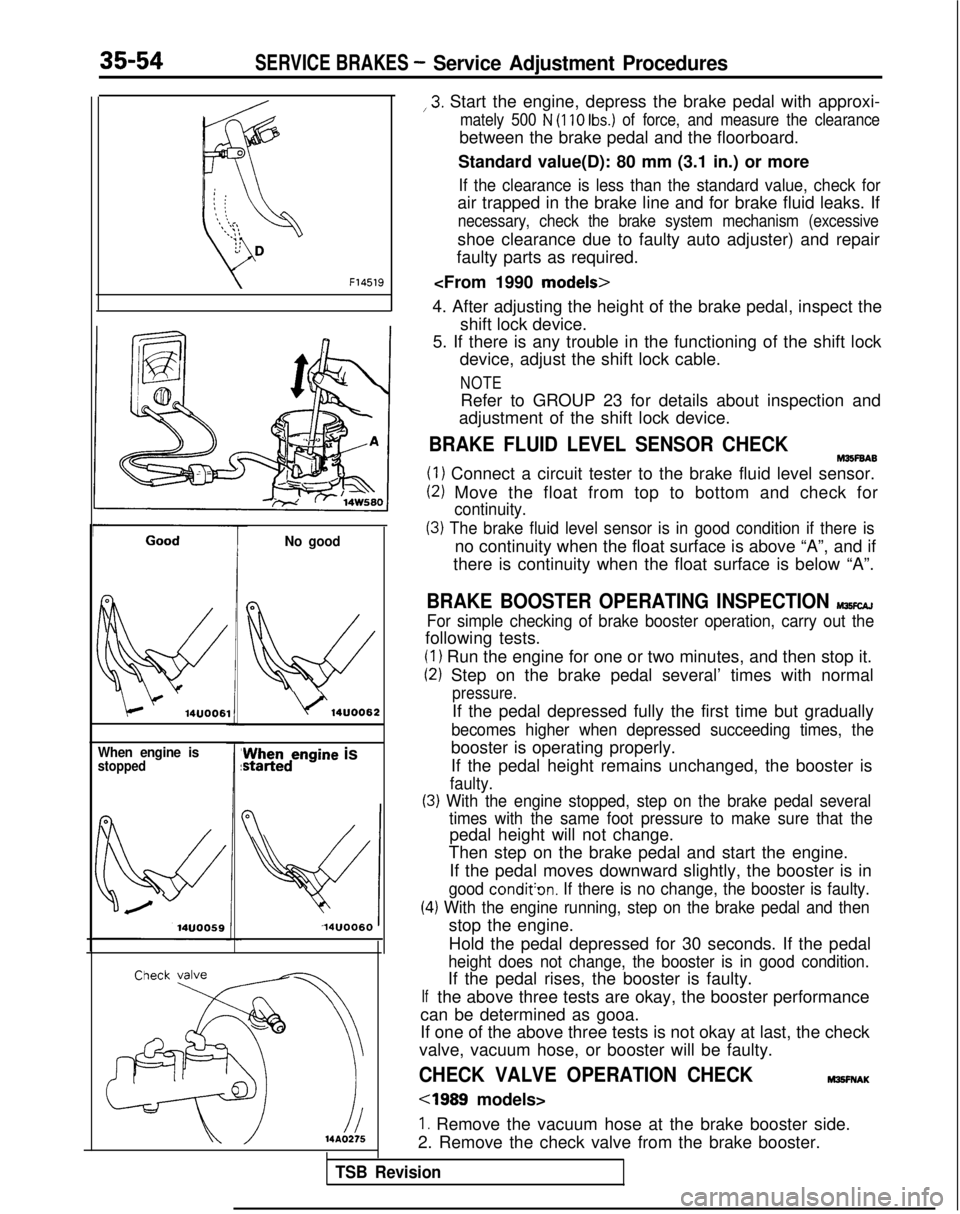
14UOO60 ,3.
Start the engine, depress the brake pedal with approxi-
mately 500 N (110 Ibs.) of force, and measure the clearance
between the brake pedal and the floorboard.
Standard value(D): 80 mm (3.1 in.) or more
If the clearance is less than the standard value, check for
air trapped in the brake line and for brake fluid leaks. If
necessary, check the brake system mechanism (excessive
shoe clearance due to faulty auto adjuster) and repair
faulty parts as required.
4. After adjusting the height of the brake pedal, inspect the shift lock device.
5. If there is any trouble in the functioning of the shift lock device, adjust the shift lock cable.
NOTE
Refer to GROUP 23 for details about inspection and
adjustment of the shift lock device.
BRAKE FLUID LEVEL SENSOR CHECKM35F6A6
(1) Connect a circuit tester to the brake fluid level sensor.
(2) Move the float from top to bottom and check for
continuity.
(3) The brake fluid level sensor is in good condition if there is
no continuity when the float surface is above “A”, and if
there is continuity when the float surface is below “A”.
BRAKE BOOSTER OPERATING INSPECTION MlKcAJ
For simple checking of brake booster operation, carry out the
following tests.
(1) Run the engine for one or two minutes, and then stop it.
(2) Step on the brake pedal several’ times with normal
pressure.
If the pedal depressed fully the first time but gradually
becomes higher when depressed succeeding times, the
booster is operating properly.
If the pedal height remains unchanged, the booster is
faulty.
(3) With the engine stopped, step on the brake pedal several
(4
If
times with the same foot pressure to make sure that the
pedal height will not change.
Then step on the brake pedal and start the engine.
If the pedal moves downward slightly, the booster is in
good condit’on. If there is no change, the booster is faulty.
.) With the engine running, step on the brake pedal and then
stop the engine.
Hold the pedal depressed for 30 seconds. If the pedal
height does not change, the booster is in good condition.
If the pedal rises, the booster is faulty.
the above three tests are okay, the booster performance
can be determined as gooa.
If one of the above three tests is not okay at last, the check
valve, vacuum hose, or booster will be faulty.
CHECK VALVE OPERATION CHECKM3!3FNAK
cl989 models>
1. Remove the vacuum hose at the brake booster side.
2. Remove the check valve from the brake booster.
TSB Revision
Page 1178 of 1273
SERVICE, BRAKES - Service Adjustment Procedures35-57
4
1
2314AQ456
FWD
Delay valve L
flc ’
-c
i1
L
3
14AO4l
mit
14RD120
AWD
51
6 2414AO4E
BLEEDING
Because the master cylinder employed is the type without the
check valve, air should be bled from the master cylinder by
following the procedures described below (if there is no brake
fluid in the master cylinder).
(1) Disconnect the brake tube from the master cylinder.
(2) Two persons’ should conduct the air bleeding, one person
slowly depressing the brake pedal and holding the pedal
depressed.
(3) In this condition, the other person should use a finger to close the outlet part of the master cylinder, and then the
first person should release the brake pedal.
(4) Steps (2) and (3) should be repeated three or four times, and then the master cylinder should be filled with brake
fluid to the specified level.
I(]OTE
The air is completely bled from the master cylinder by
steps (1) to (4).
(5) Connect the brake tube to the master cylinder.
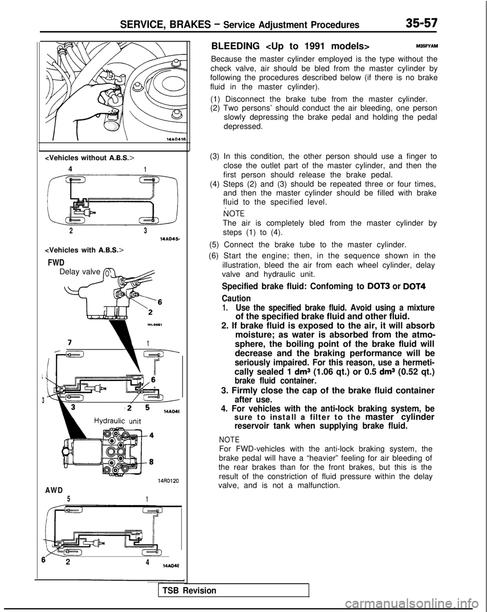
(6) Start the engine; then, in the sequence shown in the illustration, bleed the air from each wheel cylinder, delay
valve and hydraulic unit.
Specified brake fluid: Confoming to DOT3 or DOT4
Caution
1.Use the specified brake fluid. Avoid using a mixture
of the specified brake fluid and other fluid.
2. If brake fluid is exposed to the air, it will absorb moisture; as water is absorbed from the atmo-
sphere, the boiling point of the brake fluid will
decrease and the braking performance will be
seriously impaired. For this reason, use a hermeti-
cally sealed 1 dms (1.06 qt.) or 0.5 dms (0.52 qt.)
brake fluid container.
3. Firmly close the cap of the brake fluid container
after use.
4. For vehicles with the anti-lock braking system, be
sure to install a filter to the master cylinder
reservoir tank when supplying brake fluid.
NOTE
For FWD-vehicles with the anti-lock braking system, the
brake pedal will have a “heavier” feeling for air bleeding of
the rear brakes than for the front brakes, but this is the
result of the constriction of fluid pressure within the delay
valve, and is not a malfunction.
1 TSB Revision
Page 1195 of 1273
SERVICE BRAKES- Service Adjustment Procedures
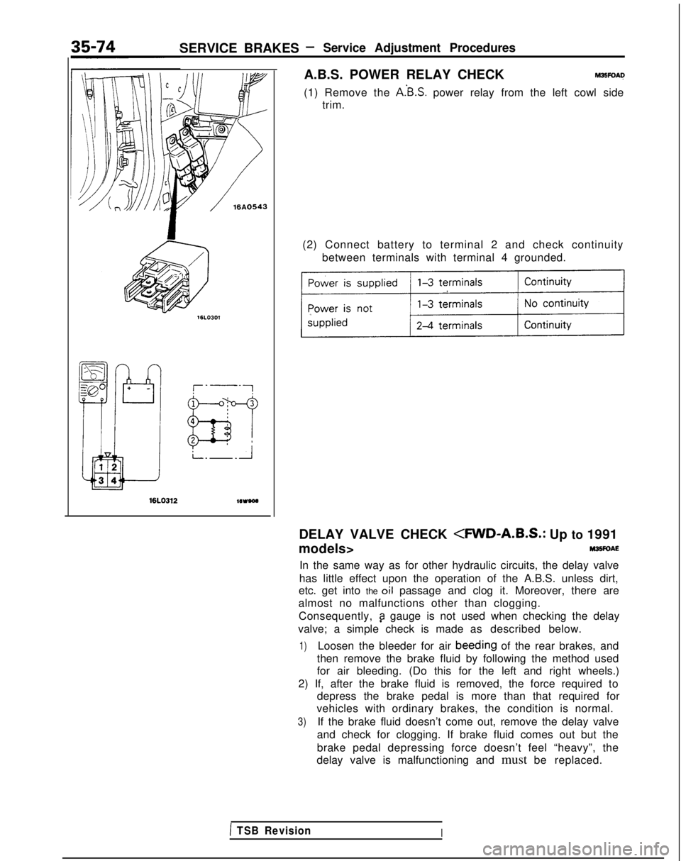
A.B.S. POWER RELAY CHECK
M3EFOAQ
(1) Remove the A.‘B.S. power relay from the left cowl side
trim.
16LO312wveoa
(2) Connect battery to terminal 2 and check continuity
between terminals with terminal 4 grounded.
DELAY VALVE CHECK
M35FOAE
In the same way as for other hydraulic circuits, the delay valve
has little effect upon the operation of the A.B.S. unless dirt,
etc. get into the oil passage and clog it. Moreover, there are
almost no malfunctions other than clogging.
Consequently,
9 gauge is not used when checking the delay
valve; a simple check is made as described below.
1)Loosen the bleeder for air beeding
of the rear brakes, and
then remove the brake fluid by following the method used
for air bleeding. (Do this for the left and right wheels.)
2) If, after the brake fluid is removed, the force required to depress the brake pedal is more than that required for
vehicles with ordinary brakes, the condition is normal.
3)If the brake fluid doesn’t come out, remove the delay valve
and check for clogging. If brake fluid comes out but the
brake pedal depressing force doesn’t feel “heavy”, the
delay valve is malfunctioning and must be replaced.
1 TSB RevisionI
Page 1207 of 1273
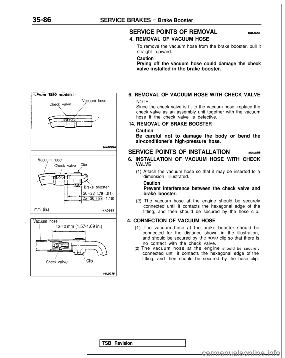
35-86SERVICE BRAKES - Brake Booster
SERVICE POINTS OF REMOVALM35JBAK
4. REMOVAL OF VACUUM HOSETo remove the vacuum hose from the brake booster, pull itstraight upward.
Caution
Prying off the vacuum hose could damage the check
valve installed in the brake booster.
Vacuum hose
14AO394
Vacuum hose
mm (in.)
14A0395
Vacuum hose
i4043 mm (1.57-1.69 in.)
I I__/
Chec/k valve ’ Clip
14LOZ15
6. REMOVAL OF VACUUM HOSE WITH CHECK VALVE
NOTE
Since the check valve is fit to the vacuum hose, replace the
check valve as an assembly unit together with the vacuum
hose if the check valve is defective.
14. REMOVAL OF BRAKE BOOSTER
Caution
Be careful not to damage the body or bend the
air-conditioner’s high-pressure hose.
SERVICE POINTS OF INSTALLATIONM35JDBB
6. INSTALLATION OF VACUUM HOSE WITH CHECK
VALVE
(1) Attach the vacuum hose so that it may be inserted to a
dimension illustrated.
Caution
Prevent interference between the check valve and
brake booster.
(2) The vacuum hose at the engine should be securely
connected until it contacts the hexagonal edge of the
fitting, and then should be secured by the hose clip.
4. CONNECTION OF VACUUM HOSE (1) The vacuum hose at the brake booster should be connected for the distance shown in the illustration,
and should be secured by
the.hose clip so that there is
no contact with the check valve.
(2) The vacuum hose at the engine should be securel
y
connected until it contacts the hexagonal edge of the
fitting, and then should be secured by the hose clip.
TSB Revision
Page 1262 of 1273
ALPHABETICAL INDEX1
A
ABS
Checking by the ABS Warnrng Light................
. 35-68-l
Troubleshooting ...........................
35-l 5-l
ABS POWER RELAY, Chec
k 35-74-l
ACCELERATOR CABLE
Inspection and Adjustment
13-398-l
Inspection and Adjustment
ACCELERATOR SWITCH, Inspection and Adjustment 13-329-I
A/C COMPRESSOR CLUTCH RELAY
On-vehicle Inspection
.............
. 13-285-l
On-vehrcle
Inspection
. 13-83-t
On-vehicle Inspection
. 13-176-l
ACTIVE-ECS ON-BOARD DIAGNOSTIC, Check......
. 338-88-I
ACTIVE-ECS RELAY.......................
. 338-141
-I
ACTIVE-ECS SENSOR....
.
...... ............ 338-138-I
ACTIVE-ECS SYSTEM
Checking by Using Alarm Light
.................
. 338-87-I
Operation Check ........................... 338-90-I
AERO PARTS..
.
........................... 51-18-l
AIR CLEANER...............................
. 15-9-I
AIR CLEANER ELEMENT
Inspection and Replacement
....................
. 15-6-l
Maintenance .......................... 00-39-l
AIR COMPRESSOR..........................
. 338-125-I
AIR CONDITIONING SWITCH
Emission control
...........................
.
17-21 -I
Heater, Air
Conditionrng
and Ventilation .............. 55-29-l
On-vehicle Inspection
On-vehicle Inspection
. 13-83-l
On-vehicle Inspection
. 13-176-l
AIR TUBE..............
.
....................... 338-133-I
ALARM LIGHT, Check. ......................... 338-87-I
ALARM SYSTEM, Theft ..........................
54-165-11
ALIGNMENT
Front Wheel, Adjustment .......................
. 33A-5-l
Rear
Wheel, inspection
. 34-23-l
Rear Wheel, Inspection
. 34-5-l
ANTENNA ......................................
54-153-11
ANTI-LOCK BRAKING SYSTEM, Troubleshooting .........
.
35-15-1
ARM
Lower
. 338-103-I
Lower
.
33A-10-I
Lower
................... 34-28-l
Torsion
.
338-l 19-l
Torsion
...................34-l 5-lTrailing
................. 34-31-l
Upper
.................. 34-28-l
AUDIO
SYSTEM................
.
.................
54-l 12-11
AUTO-CRUISE CONTROL. ..........................
. 13-408-I
AUTO-CRUISE CONTROL INDIVIDUAL PARTS, inspection..
. 13-401-I
AUTO-CRUISE CONTROL SYSTEM...................
. 13-332-l
AUTO-CRUISE CONTROL SYSTEM, Inspection..........
. 13-397-l
AUTOMATIC TRANSAXLE, Maintenance ................. 00-43-I
AXLE
Rear, Maintenance
...............................
. 00-45-I
Torsion
.
338-l 19-l
Torsion
.
......................... 34-15-l
AXLE HUB
Rear
Rear CFWD-Rear
Drum Brakes> ................... 27-6-l
AXLE SHAFT
.
27-17-1
B
BACKLASH. Total, Rear Axle, Check
. 27-15-l
BALL JOINT
Rotation Starting Torque Check ...................... 378-8-I
Tie Rod End, Staning Torque Check .................. 37A-15-l
Tie Rod End, Variation Check ....................... 37A-15-l
BALL JOINT SEALS, Maintenance ..................... 00-45-I
BAR
Stabilizer
. 338-106-I
Stabilizer
. 33A-13-l
Stabilizer
. 34-37-l
BAROMETRIC PRESSURE SENSOR
On-vehicle Inspection
................
. 13-266-l
On-vehicle Inspection
On-vehicle Inspection
. 13-154-l
BASIC IDLE SPEED
Adjustment
...........................
. 13-245-l
Adjustment
Adjustment
. 13-133-l
BATTERY.........................................
.
54-2-11
BATTERY, Flat Remedy.
.............................
. 35-75-l
BEARING
Wheel, Adjustment
. 338-87-I
Wheel, Adjustment
BELT
Drive, Compressor, Adjustment
....................
. 55-17-l
Drive (For Water Pump and Generator), Maintenance ..... 00-41-I
Drive, Tension Adjustment
Drive, Tension Adjustment
Seat..........................................
. 52-39-l
Timing
Timing
. 11-34-l
Timing, Maintenance ............................... 00-40-I
Timing, Tension Adjustment
BLEEDING
Clutch
..........................................
. 21-6-l
4ws...........................................
. 370-4-I
Service Brakes. .................................. 35-57-l
Steering ........................................ 37A-22-l
BLOWER..........................................
. 55-32-l
BOOSTER
Brake
.........................................
. 35-85-l
Brake, Operating Inspection ......................... 35-54-l
BOOST METER, On-vehicle Inspection
BOOTS, Drive Shaft, Maintenance ....................... 00-45-I
BRAKE
Disc, Front
......................................
. 35-94-l
Disc, Rear.....................................
.
35-l 14-l
BRAKE BOOSTER
...................................
. 35-85-l
BRAKE BOOSTER, Operating Inspection .................. 35-54-l
BRAKE DISC
Front, Run-out Check.
.............................
. 35-63-l
Front, Run-out Correction ........................... 35-64-l
Front, Thickness Check ............................. 35-65-l
Rear, Run-out Check ............................... 35-66-l
Rear, Run-out Correction. ........................... 35-66-l
Rear, Thickness Check............................
. 35-66-l
BRAKE DRUM, tnside
Diameter, Check ................... 35-67-l
BRAKE FLUID LEVEL SENSOR, Check...................
. 35-54-l
BRAKE FLUID PRESSURE SWITCH
AWD-ABS (Up to 1991 Models)
....................
.
35-133-l
AWD-ABS
(Up to 1991 models), Check ...............
. 35-75-l
BRAKE HOSES, Maintenance ........................... 06-45-t
BRAKELINE
........................................
35-87-l