1989 MITSUBISHI GALANT air condition
[x] Cancel search: air conditionPage 1008 of 1273
ACTIVE-ELECTRONIC CONTROL SUSPENSION - Troubleshooting 33B-69
Operation
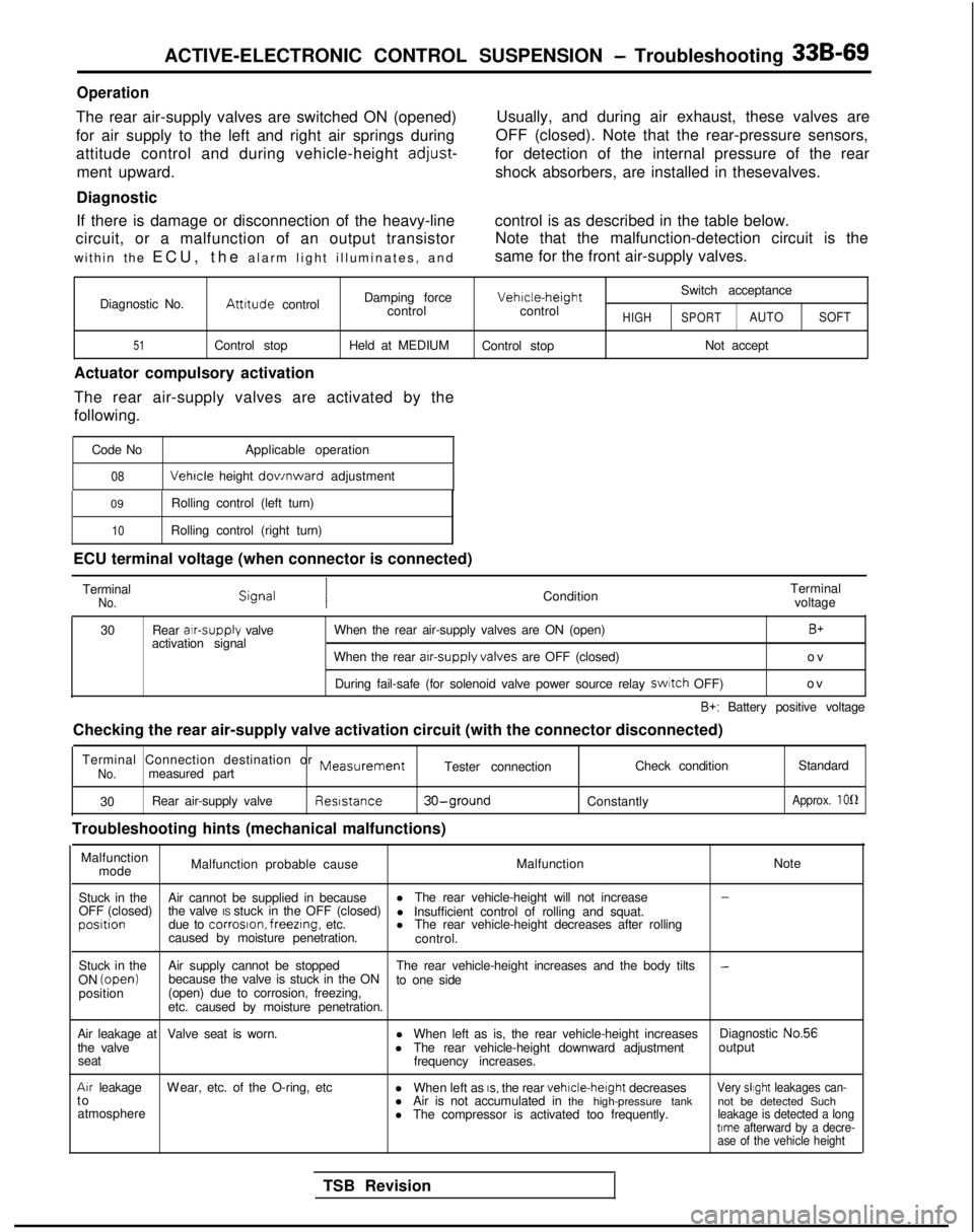
The rear air-supply valves are switched ON (opened)
for air supply to the left and right air springs during
attitude control and during vehicle-height
adjust-
ment upward.
Diagnostic Usually, and during air exhaust, these valves are
OFF (closed). Note that the rear-pressure sensors,
for detection of the internal pressure of the rear shock absorbers, are installed in thesevalves.
If there is damage or disconnection of the heavy-line control is as described in the table below.
circuit, or a malfunction of an output transistor Note that the malfunction-detection circuit is the
within the ECU, the alarm light illuminates, and same for the front air-supply valves.
Switch acceptance
Diagnostic No.
Attrtude control Damping force Vehrcle-height
control controlHIGHSPORTAUTO SOFT
51Control stop Held at MEDIUM
Control stop Not accept
Actuator compulsory activation
The rear air-supply valves are activated by the
following.
Code No Applicable operation
08 Vehicle
height dov/nward adjustment
09 Rolling control (left turn)
10Rolling control (right turn)
ECU terminal voltage (when connector is connected)
Terminal
No.Condition Terminal
voltage
30 Rear alr-supply
valve
activation signal When the rear air-supply valves are ON (open)
B+
When the rear arr-supply valves
are OFF (closed) ov
During fail-safe (for solenoid valve power source relay switch
OFF) ov
B+: Battery positive voltage
Checking the rear air-supply valve activation circuit (with the connect\
or disconnected)
Terminal Connection destination or
MeasurementNo.measured part Tester connection
Check condition
Standard
30 Rear air-supply valve Reststance
30-ground
Troubleshooting hints (mechanical malfunctions)
Constantly
Approx. 1012
Malfunction
mode Malfunction probable cause
MalfunctionNote
Stuck in the Air cannot be supplied in because l
The rear vehicle-height will not increase
-
OFF (closed) the valve IS stuck in the OFF (closed)
l Insufficient control of rolling and squat.posrtion
due to corroson. freezrng,
etc. lThe rear vehicle-height decreases after rolling
caused by moisture penetration. control.
Stuck in the Air supply cannot be stopped The rear vehicle-height increases and the body tilts
-ON (open)
because the valve is stuck in the ON
to one side
position (open) due to corrosion, freezing,
etc. caused by moisture penetration.
Air leakage at Valve seat is worn. lWhen left as is, the rear vehicle-height increases Diagnostic No.56
the valve lThe rear vehicle-height downward adjustment output
seat frequency increases.
Arr leakageW
ear, etc. of the O-ring, etc
lWhen left as
IS, the rear vehrcle-height
decreasesVery slrght leakages can-t
o
lAir is not accumulated in the high-pressure tank not be detected Such
atmosphere lThe compressor is activated too frequently.
leakage is detected a longtrme afterward by a decre-
ase of the vehicle height
TSB Revision
Page 1010 of 1273
ACTIVE-ELECTRONIC CONTROL SUSPENSION - Troubleshooting 33B-71
Operation
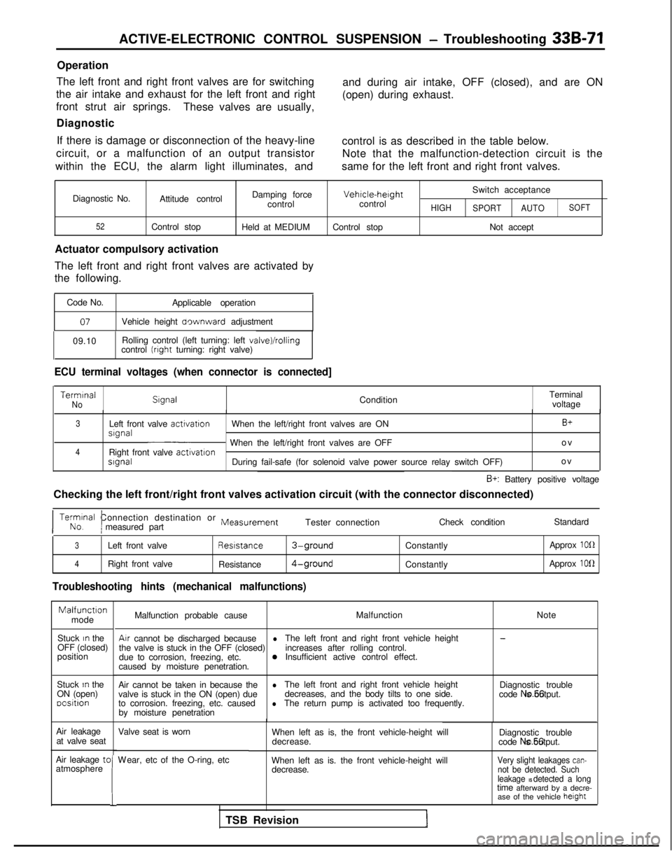
The left front and right front valves are for switching
the air intake and exhaust for the left front and right
front strut air springs. These valves are usually,
Diagnostic and during air intake, OFF (closed), and are ON
(open) during exhaust.
If there is damage or disconnection of the heavy-line control is as described in the table below.
circuit, or a malfunction of an output transistor Note that the malfunction-detection circuit is the
within the ECU, the alarm light illuminates, and same for the left front and right front valves.
Diagnostic No.
52
Damping forceVehicle-herghtSwitch acceptance
Attitude control controlcontrol
HIGH
SPORT AUTOSOFT
Control stop
Held at MEDIUM Control stop Not accept
Actuator compulsory activation
The left front and right front valves are activated by
the following.
Code No. Applicable operation
07Vehicle height aownward adjustment
09.10 Rolling control (left turning: left
valve)/rollingcontrol (rrght turning: right valve)
ECU terminal voltages (when connector is connected] Termrnal
No
Slgnal
ConditionTerminal
voltage
3Left front valve activatron
When the left/right front valves are ONB+srgnal~ When the left/right front valves are OFF o
v
4Right front valve
activatronsrgnalDuring fail-safe (for solenoid valve power source relay switch OFF)
o
v
B+: Battery positive voltage
Checking the left front/right front valves activation circuit (with the\
connector disconnected)
I No. Terminal
Connection destination or
Measurement
Imeasured part Tester connection
Check conditionStandard
3Left front valve Resrstance3-groundConstantly
Approx 1012
4Right front valve
Resistance4-groundConstantly Approx 1012
Troubleshooting hints (mechanical malfunctions)Malfunctron
mode
Stuck
In the
OFF (closed)
position
Stuck
In the
ON (open) oositron
Air leakage at valve seat
Air leakage tc
atmosphere
!
Malfunction probable cause Malfunction
NoteAir
cannot be discharged because
l-
the valve is stuck in the OFF (closed) The left front and right front vehicle height
due to corrosion, freezing, etc. increases after rolling control.0Insufficient active control effect.
caused by moisture penetration.
Air cannot be taken in because the
lvalve is stuck in the ON (open) due The left front and right front vehicle height
Diagnostic trouble
decreases, and the body tilts to one side.
to corrosion. freezing, etc. caused code No.56 is output.lThe return pump is activated too frequently.
by moisture penetration
Valve seat is worn
W
ear, etc of the O-ring, etc
When left as is, the front vehicle-height will
decrease. Diagnostic trouble
code No.56 is output.
When left as is. the front vehicle-height will decrease.
Very slight leakages can-not be detected. Such
leakage IS detected a longtime afterward by a decre- ase of the vehicle height
TSB Revision
Page 1012 of 1273
ACTIVE-ELECTRONIC CONTROL SUSPENSION - Troubleshooting 33B-73
Operation
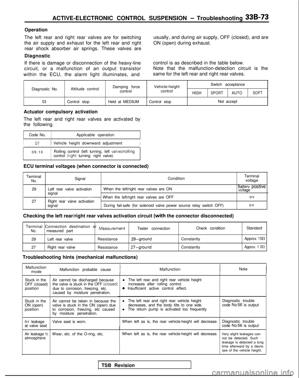
The left rear and right rear valves are for switching
the air supply and exhaust for the left rear and right rear shock absorber air springs. These valves are
Diagnostic usually, and during air supply, OFF (closed), and are
ON (open) during exhaust.
If there is damage or disconnection of the heavy-line
circuit, or a malfunction of an output transistor
within the ECU, the alarm light illuminates, and control is as described in the table below.
Note that the malfunction-detection circuit is the
same for the left rear and right rear valves.
Diagnostic No.
53
Damping force Vehicle-height Switch acceptance
Attitude control controlcontrol
HIGHSPORTAUTOSOFT
Control stop
Held at MEDIUMControl stop Not accept
Actuator compulsory activation
The left rear and right rear valves are activated by
the following.
Code No. Applicable operation
I07/ Vehicle height downward adjustmentI
09.1
0
Rolling control (left turning, left
valve)/rollingcontrol (right
turning: right valve)
ECU terminal voltages (when connector is connected) Terminal
No.Signal ConditionTerminal
voltage
29 Left rear valve activation When the left/right rear valves are ON
signal
E3a3azg~ positive
~ When the left/right rear valves are OFF o
v
27 Right rear valve activation
signal During fail-safe (for solenoid valve power source relay switch OFF) ov
Checking the left rear/right rear valves activation circuit (with
the connector disconnected)
Terminal Connection destination or
MeasurementNo.measured part Tester connection
29 Left rear valve Resistance
29-ground
27Right rear valve
Resistance27-ground
Troubleshooting hints (mechanical malfunctions) Check condition
Constantly
Constantly Standard
Approx
1011
Approx. 1 Of2
Malfunction mode Malfunction probable cause
IMalfunction
Note
Stuck in the
OFF (closed)
position
Stuck in the
ON (open)
position
Air leakage
at valve seat
Air leakage
tcatmosphere Air cannot be discharged because
l
The left rear and right rear vehicle height
the valve is stuck in the OFF (closed)
increases after rolling control.
due to corrosion, freezing, etc. 0
Insufficient active control effect.
caused by moisture penetration.
Air cannot be taken in because the
lThe left rear and right rear vehicle height
valve is stuck in the ON (open) due decreases, and the body tilts to one side.
to corrosion, freezing, etc caused l
The return pump is activated too frequently
by moisture penetration.
Valve seat is worn. When left as is, the rear vehicle-height will decrease.
W
ear, etc. of the O-ring, etc.
When left as is, the rear vehicle-height will decrease.
TSB Revision Diagnostic trouble
code
No.56 is output
Diagnostic trouble
code
No.56 is output
Very slight leakages can- not be detected. Such
leakage is detected a long
time afterward by a decre- ase of the vehicle height.
Page 1028 of 1273
ACTIVE-ELECTRONIC CONTROL SUSPENSION - ~~:i%,~:iustment 33B-89
Without
disconnecting
:he air tubing
Remaining
pressure
P =
120 kPa
(17 psi)
By disconnecting the
fir tubing
normal
condition
P ‘=.0
Front
tear (From 1990
model!
rmzIIconditlui
12AO281
Vehicle-height switch 6. If the vehicle height is not within the standard value,
loosen the turnbuckles of the front and rear height sensor
rods, and then make the adjustment by changing the
length of the rods. The vehicle height becomes higher
when the rods are lengthened.
Caution 1. Both the front and rear heights must be checked, because, even though only the front or the rear is
adjusted, the other height (rear or front) is also
changed.
2. The adjustments of the vehicle height must be made
while the engine is idling (vehicle stopped).
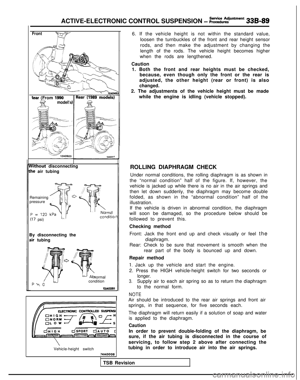
ROLLING DIAPHRAGM CHECK Under normal conditions, the rolling diaphragm is as shown in
the “normal condition” half of the figure. If, however, the
vehicle is jacked up while there is no air in the air springs and
then let down suddenly, the diaphragm may become double
folded, as shown in the “abnormal condition” half of the
illustration.
If the vehicle is driven in abnormal condition, the diaphragm
will soon be damaged, so the procedure below should be
followed to prevent this.
Checking method
Front: Jack the front end up and check visually or feel th
e
diaphragm.
Rear: Check to be sure that movement is smooth when the
rear part of the body is bounced up and down.
Repair method
1. Jack up the vehicle and start the engine.
2. Press the HIGH vehicle-height switch for two seconds or
longer.
3.Supply air to each air spring so as to return the diaphragm
to the normal form.
NOTE
Air should be introduced to the rear air springs and front air springs, in that sequence, for five seconds each.
The diaphragm will return easily if a solution of soap and water is applied to the diaphragm.
Caution
In order to prevent double-folding of the diaphragm, be
sure, if the air tubing is disconnected in the course of
servicing, to follow step 2 above after connecting the
tubing in order to introduce air into the air springs.
74AOOQ8
TSB Revision
Page 1034 of 1273
ACTIVE-ELECTRONIC CONTROL SUSPENSION - ;;:i~%:?~~“~
33B-95
Adaptor E (MB991227)
Shut-off valve 12A.0350
iigh-pressure
witch
Air-pressure gauge (MB991075)
Adaptor C
(MB991 075.q
,daptor E (MB991226) /P-
3intH &‘xb
2.
3.
4.
5.
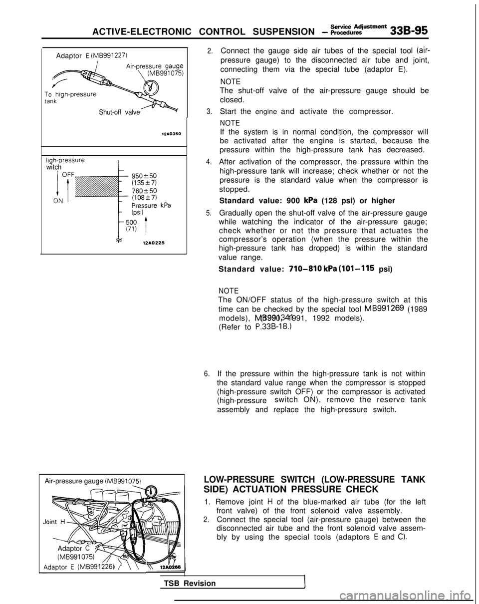
Connect the gauge side air tubes of the special tool (air-
pressure gauge) to the disconnected air tube and joint,
connecting them via the special tube (adaptor E).
NOTE
The shut-off valve of the air-pressure gauge should be closed.
Start the engine and activate the compressor.
NOTE
If the system is in normal condition, the compressor will
be activated after the engine is started, because the
pressure within the high-pressure tank has decreased.
After activation of the compressor, the pressure within the high-pressure tank will increase; check whether or not the
pressure is the standard value when the compressor is
stopped.
Standard value: 900
kPa (128 psi) or higher
Gradually open the shut-off valve of the air-pressure gauge
while watching the indicator of the air-pressure gauge; check whether or not the pressure that actuates the
compressor’s operation (when the pressure within the
high-pressure tank has dropped) is within the standard
value range.
Standard value:
710-810 kPa (101-115 psi)
NOTE
The ON/OFF status of the high-pressure switch at this time can be checked by the special tool MB991269
(1989
models), MB991341 (1990, 1991, 1992 models).
(Refer to
P.33B-18.)
6.If the pressure within the high-pressure tank is not within
the standard value range when the compressor is stopped
(high-pressure switch OFF) or the compressor is activated
(high-pressure switch ON), remove the reserve tank
assembly and replace the high-pressure switch.
LOW-PRESSURE SWITCH (LOW-PRESSURE TANK
SIDE) ACTUATION PRESSURE CHECK
1. Remove joint
H of the blue-marked air tube (for the left
front valve) of the front solenoid valve assembly.
2.Connect the special tool (air-pressure gauge) between the
disconnected air tube and the front solenoid valve assem-
bly by using the special tools (adaptors
E and C).
TSB RevisionI
Page 1035 of 1273
338-96
ACTIVE-ELECTRONIC CONTROL SUSPENSION - ;;~:;u~:iusment
Low-pressure
switch
PressurekPa (psi)
I
OFF
t
140 (20)
70 (10)
ON
12AO226
12A04P
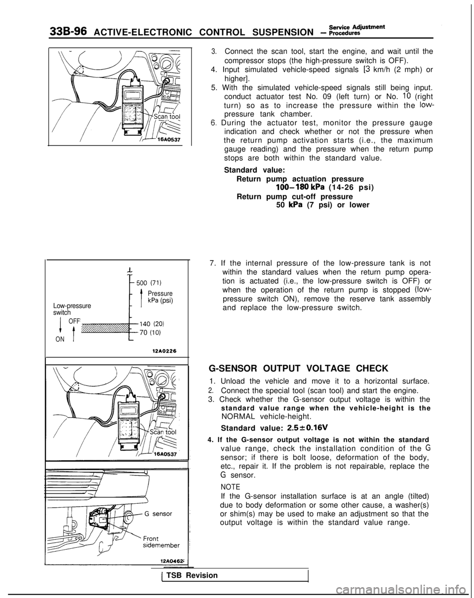
3.Connect the scan tool, start the engine, and wait until the
compressor stops (the high-pressure switch is OFF).
4. Input simulated vehicle-speed signals
[3 km/h (2 mph) or
higher].
5. With the simulated vehicle-speed signals still being input. conduct actuator test No. 09 (left turn) or No.
IO (right
turn) so as to increase the pressure within the
low-
pressure tank chamber.
6. During the actuator test, monitor the pressure gauge indication and check whether or not the pressure when
the return pump activation starts (i.e., the maximum gauge reading) and the pressure when the return pump
stops are both within the standard value.
Standard value: Return pump actuation pressure
loo-180 kPa (14-26 psi)
Return pump cut-off pressure 50
kPa (7 psi) or lower
7. If the internal pressure of the low-pressure tank is not within the standard values when the return pump opera-
tion is actuated (i.e., the low-pressure switch is OFF) or
when the operation of the return pump is stopped
(low-
pressure switch ON), remove the reserve tank assembly
and replace the low-pressure switch.
G-SENSOR OUTPUT VOLTAGE CHECK 1. Unload the vehicle and move it to a horizontal surface.
2.Connect the special tool (scan tool) and start the engine.
3. Check whether the G-sensor output voltage is within the standard value range when the vehicle-height is theNORMAL vehicle-height.
Standard value:
2.520.16V
4. If the G-sensor output voltage is not within the standard value range, check the installation condition of the
G
sensor; if there is bolt loose, deformation of the body,
etc., repair it. If the problem is not repairable, replace the
G sensor.
NOTE
If the G-sensor installation surface is at an angle (tilted)
due to body deformation or some other cause, a washer(s)
or shim(s) may be used to make an adjustment so that the
output voltage is within the standard value range.
1 TSB Revision
Page 1068 of 1273
ACTIVE-ELECTRONIC CONTROL SUSPENSION - &ttid Va’ve and 33B-129
12A0369
1 nql \- I E
II-II-II-II--~
G
DFIH12AO292
soap-and-water
solution.
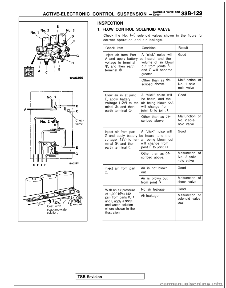
INSPECTION
1. FLOW CONTROL SOLENOID VALVE
Check the No. l-3 solenoid valves shown in the figure for
correct operation and air leakage.
TSB Revision Check item
Condition Result
Inject air from Part A “click” noise will
Good
A and apply battery be
heard, and the
voltage to terminal volume of air blown
0, and then earthout from joints B
terminal 0.and C will become
greater.
Other than as
de-Malfunction of
scribed
abooe.No. 1 sole-
noid valve
Blow air in at joint A “click” noise will
Good
E. apply batterybe heard, and the
voltage (12V) to ter- air being blown out
minal 0, and then will change from
earth terminal
0.joint D to joint I.
Other than as de-Malfunction of
scribed above No. 2 sole-
noid valve
inject air from part A “click” noise will
Good
G and apply battery
be heard, and the
voltage
(12~) to ter- air being blown out
minal
@, and then will change from
earth terminal
0.joint F to joint H
.
Other than as
de-Malfunction of
scribed above. No.
3 sole
-
noid
valve
nject air from part Air is not blown GoodPir.out.
Air is blown out Malfunction of
from joint
B.check valve
W
ith an air pressure
No air leakage
Good
of 1,000
kPa (142 Malfunction of
psi) from parts 9, HAir leakage
solenoid valve
and I, apply a soap-seal
and-water solution
where shown in the illustration.
Page 1069 of 1273
33B-130 ACTIVE-ELECTRONIC CONTROL SUSPENSION - ?Eid “=lve and
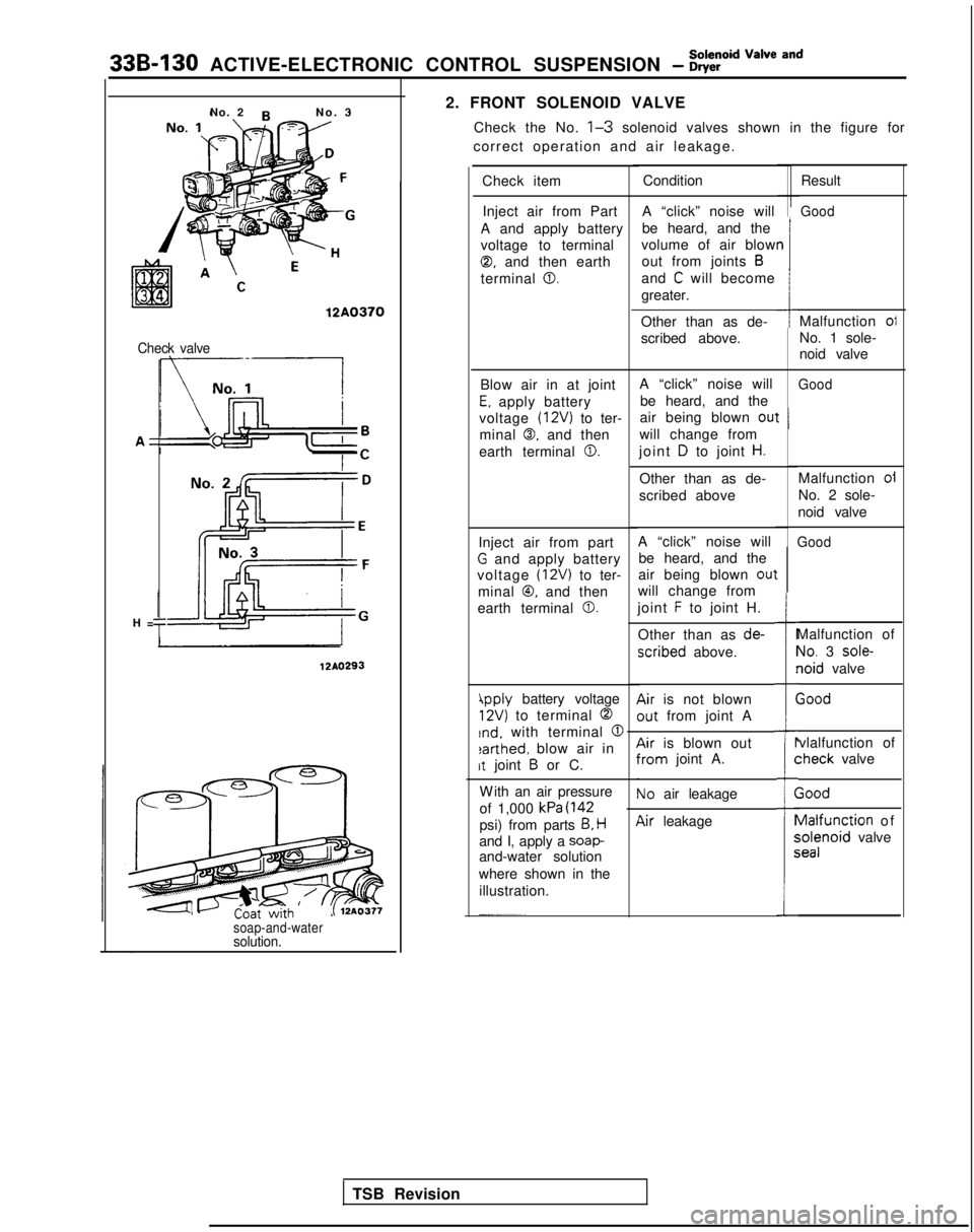
2. FRONT SOLENOID VALVECheck the No.
l-3 solenoid valves shown in the figure for
correct operation and air leakage.
No. 2
No.
3
Check item Result
Good
Condition
Inject air from Part
A and apply battery
voltage to terminal
0, and then earth
terminal
0.
A “click” noise will
be heard, and the
volume of air blow out from joints
B
and C will become
greater.
n
112A0370Malfunction oi
No. 1 sole-
noid valve
Other than as de-
scribed above.Check valve
A “click” noise will
be heard, and the
air being blown
ou’
will change from
joint
D to joint H.
GoodBlow air in at joint
E, apply battery
voltage
(12V) to ter-
minal
0. and then
earth terminal
0.
t I
H
=
Malfunction oi
No. 2 sole-
noid valve
Other than as de-
scribed above
A “click” noise will be heard, and the
air being blown
0u1
will change from
joint
F to joint H.
Other than as de-
xribed above.
Air is not blown
out from joint A
GoodInject air from part
G and apply battery
voltage
(12V) to ter-
minal
@, and then
earth terminal
0.
t
I=
i
r
(
Malfunction of
Yo. 3 sole-
loid valve
;ood
12AO293
4pply battery voltage
12V) to terminal 0
rnd. with terminal @
earthed, blow air in
rt joint B or C.
vlalfunction of :heck
valve
r
C
(
1
P
5c
Air is blown outYom joint A.
Vo air leakage
W
ith an air pressure
of 1,000
kPa (142
psi) from parts B, H
and I, apply a soap-and-water solution
where shown in the illustration.
;ood vlalfunction
of ;olenoid
valve ieal
lir leakage
soap-and-watersolution.
TSB Revision