Page 556 of 1273

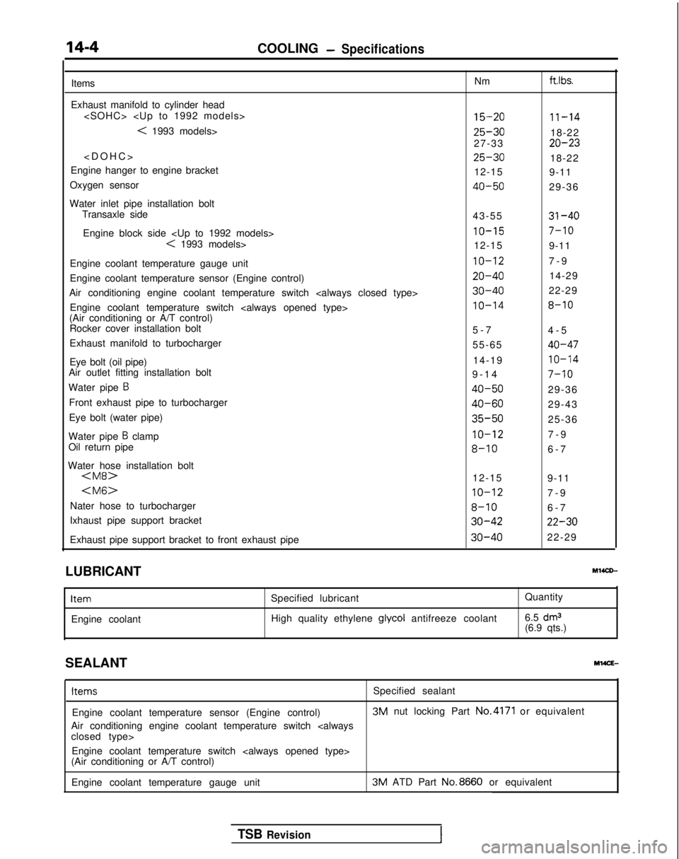
14-4COOLING-Specifications
Items
Exhaust manifold to cylinder head
< 1993 models>
>
Engine hanger to engine bracket
Oxygen sensor
Water inlet pipe installation bolt Transaxle side
Engine block side
< 1993 models>
Engine coolant temperature gauge unit
Engine coolant temperature sensor (Engine control)
Air conditioning engine coolant temperature switch
Engine coolant temperature switch
(Air conditioning or A/T control) Rocker cover installation bolt
Exhaust manifold to turbocharger
Eye bolt (oil pipe)
Air outlet fitting installation bolt
Water pipe
B
Front exhaust pipe to turbocharger
Eye bolt (water pipe)
Water pipe
B clamp
Oil return pipe
Water hose installation bolt
Nater hose to turbocharger
Ixhaust pipe support bracket
Exhaust pipe support bracket to front exhaust pipe Nm ft.lbs.
15-2011-14
25-3018-22
27-3320-23
25-3018-22
12-15 9-11
40-5029-36
43-55
31-40
IO-157-10
12-15 9-11
IO-127-
9
20-4014-29
30-4022-29
IO-148-10
5-
7
4-5
55-65
40-47
14-19IO-14
9-1
4
7-10
40-5029-36
40-6029-43
35-5025-36
IO-127-
9
8-106-
7
12-15 9-11
IO-127-
9
8-106-
7
30-4222-30
30-4022-29
LUBRICANT Ml4CD-
Item
Engine coolant
Specified lubricant
High quality ethylene glycol
antifreeze coolant Quantity
6.5
dm3(6.9 qts.)
SEALANT
M14CE- Items
Specified sealant
Engine coolant temperature sensor (Engine control) 3M
nut locking Part No.4171
or equivalent
Air conditioning engine coolant temperature switch
closed type> Engine coolant temperature switch
(Air conditioning or A/T control)
Engine coolant temperature gauge unit 3M
ATD Part No.8660
or equivalent
TSB Revision
Page 559 of 1273

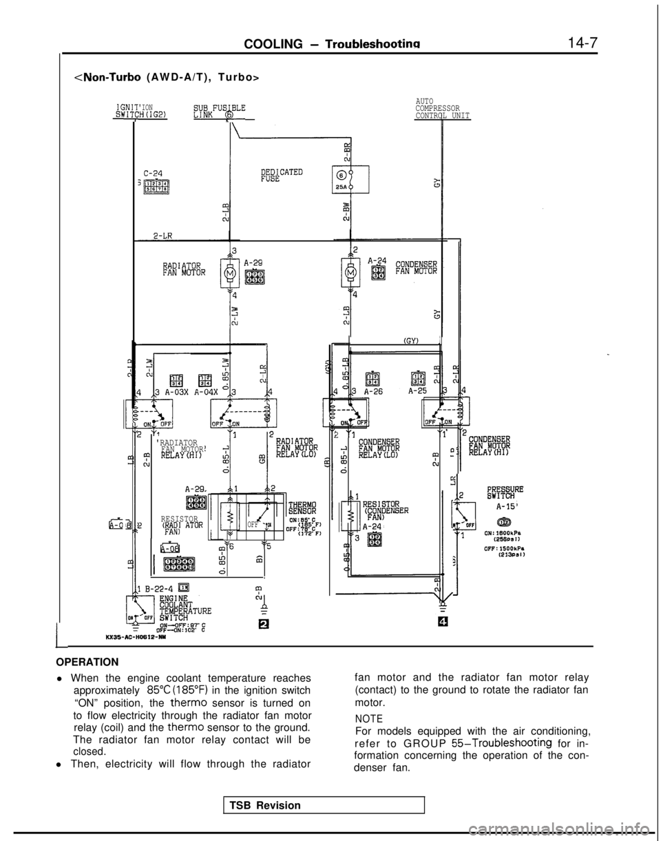
COOLING -Troubleshootina14-7
L
ICSk-iNIq
ci
'ION:H(IG2)
W&FUS$BLE
AUTOCOMPRESSOR
CONTROL UNIT
A-29
'RADIATORFAN MOTOR43 RELAYCHI)cu
A-29
RESISTOR
> 'Mf AToR
m ON:SSC
OFF -p(165'F)
OFF:?8’C(172’F)$5m6‘5I%
66.
B-22-4 m
?
"A
OFF-ON:
102’
C0 KX35-AC-H0612-NY
I(GY) ;
2 "1"1
;-'SX!D%% BRELAY(L0) 0? -
N
d
0-
A-24
2
f
A-15
I
/OFFGE3
1
0N:lBOOkPa(256DS
II 0FF:lSOOkPs
2
(213PSl)
OPERATION l When the engine coolant temperature reaches approximately
85°C (185°F) in the ignition switch
“ON” position, the
therm0 sensor is turned on
to flow electricity through the radiator fan motor relay (coil) and the
therm0 sensor to the ground.
The radiator fan motor relay contact will be
closed.
l Then, electricity will flow through the radiator fan motor and the radiator fan motor relay
(contact) to the ground to rotate the radiator fan
motor.
NOTE
For models equipped with the air conditioning,
refer to GROUP
55-Troubleshooting for in-
formation concerning the operation of the con-
denser fan.
TSB Revision
Page 561 of 1273
COOLING - Radiator
RADIATOR
REMOVAL AND INSTALLATION
14-9
M14OA-
Pre-removal and Post-installation
@Draining and Supplying of the En-gine Coolant
(Refer toGROUP 00-Maintenancekervice.)
9-14 Nm
(j/-&j
:Vehicles with anti-lock&
braking system>
9-14
Nm7-10 ft.lbs.
4-6 Nm3-4 ftlbs.04AOO48
2-4 ft.lbs.
Removal steps
1. Branch tube bracket
2. Branch tube
3. Radiator cap
4. Drain plug
5. Overflow tube
6. Reserve tank
41) l +7. Radiator upper hose+e ,+ 8. Radiator lower hose
a+9. Automatic transaxle oil cooler hoses 10. Therm0
sensor connector
11. Radiator fan motor COnneCtOr12. Condenser fan motor connector
(FWD, AWD-MIT&Vehicleswith air conditioning>13. Upper insulator
14. Radiator assembly
15. Radiator fan motor assembly
16. Condenser fan motor assembly17. Therm0 sensor
18. Lower insulator
TSB Revision
Page 567 of 1273
COOLING - Water Pump
WATER PUMP REMOVAL AND INSTALLATION14-15
M14MEA
? /’I
50-65 Nm36-47 ft.lbs. a(Refer to GROUP 00-Maintenance
Post-installation Operation*Installation of the Under Cover
*Supplying of the Engine Coolant
(Refer to GROUP 00-MaintenanceService.)aEngine Adjustment
(Refer to GROUP 1 l-Service
Adjustment Procedures.)
/30-40 Nm
22-29 ft.lbs. 14-22
ft.lb=
\
6
03AOl39
Removal steps
I23-27 Nm3IT-20 ft.lbs.
OlAOOlO
I. Clamp part of hoses (Power steering and
air conditioning)
2. Engine mount bracket
3. Drive belt (Air conditioning) (Refer
t0GROUP 00-Maintenance Service.)
4. Drive belt (Power steering) (Refer toGROUP 00-Maintenance Service.)
5. Drive belt (Refer to GROUP OO-Maintenance Service.)
6. Tension pulley bracket
7. Water pump pulley (Power steering)
8. Water pump pulley
9. Damper pulley
TSB Revision1
Page 572 of 1273

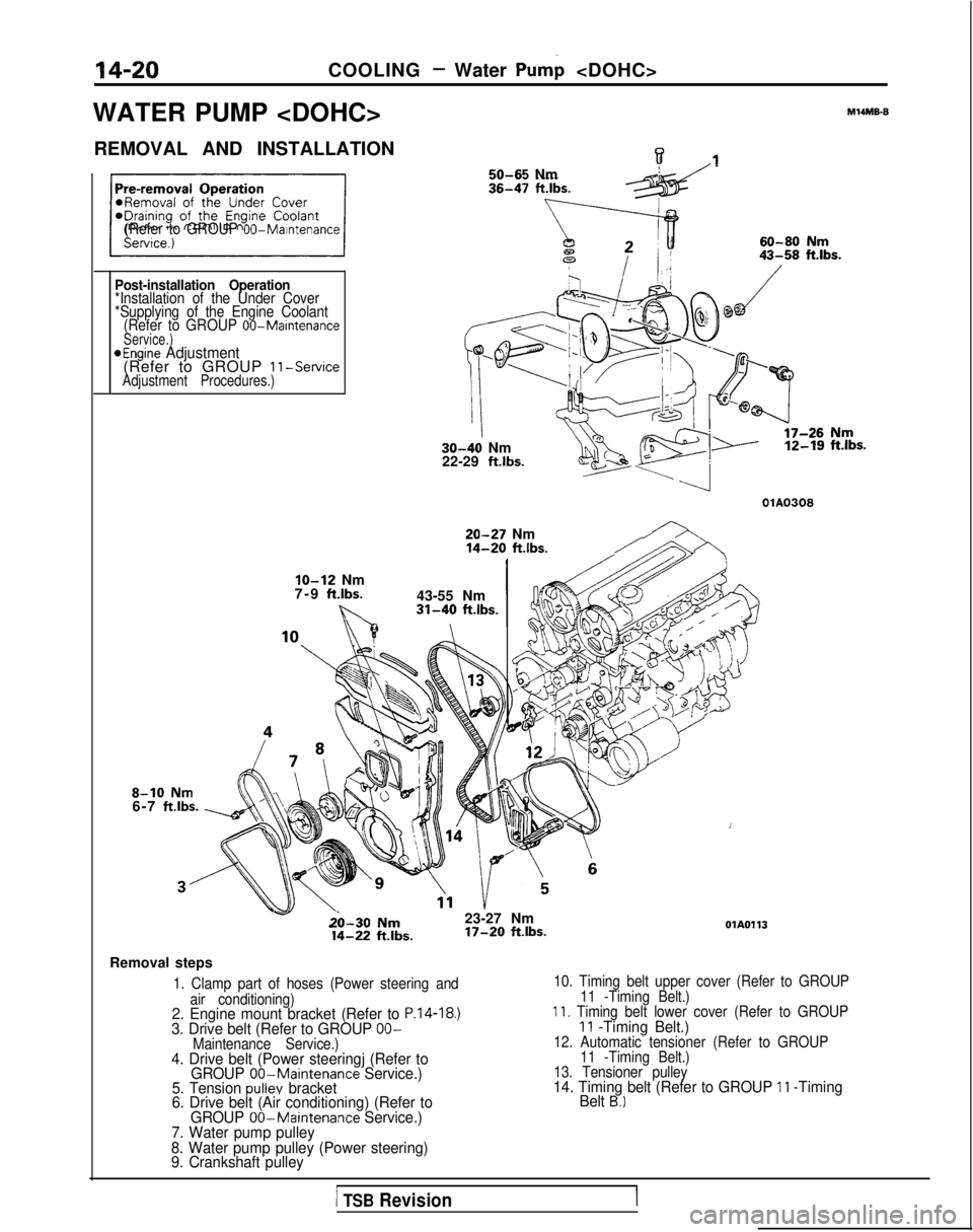
14-20COOLING - Water Pump
WATER PUMP
M14ME6
REMOVAL AND INSTALLATIONw.I50-65 Nm
(Refer to GROUP 00-Maintenance
Post-installation Operation*Installation of the Under Cover
*Supplying of the Engine Coolant (Refer to GROUP
00-MaintenanceService.)aEngine Adjustment(Refer to GROUP 11-ServiceAdjustment Procedures.)
30-40 Nm
22-29 ft.lbs. 12-19
ft.lbs.
OlA0308
20-27 Nm14-20 ft.lbs./
8-10 Nm6-7 ftlbs.
IO-12 Nm
7-9 ft.lbs.
b..
43-55 Nm31-40 ft.lbs.
v&l-30 Nm23-27 Nm 14-22
ftlbs. 17-20
ft.lbs.OlA0113
Removal steps
1. Clamp part of hoses (Power steering and
air conditioning)
2. Engine mount bracket (Refer to P.14-18.)3. Drive belt (Refer to GROUP OO-Maintenance Service.)4. Drive belt (Power steeringj (Refer to GROUP 00-Maintenance Service.)
5. Tension pullev bracket
6. Drive belt (Air conditioning) (Refer to
10. Timing belt upper cover (Refer to GROUP
11 -Timing Belt.)
11. Timing belt lower cover (Refer to GROUP11 -Timing Belt.)12. Automatic tensioner (Refer to GROUP11 -Timing Belt.)
13. Tensioner pulley
14. Timing belt (Refer to GROUP 11 -Timing
Belt B.)
GROUP 00-Maintenance Service.)
7. Water pump pulley
8. Water pump pulley (Power steering)
9. Crankshaft pulley
1 TSB RevisionI
Page 576 of 1273
14-24COOLING - Water Hose and Water Pipe
WATER HOSE AND WATER PIPE
M141A-B
REMOVAL AND INSTALLATION
Pre-removal and Post-installation
ODeration*braining and Supplying of the Engine
12-15 Nm
4(,-s‘, ,,,,,, /
29-36 ftlbs.
/
, ‘r- y’ ft”bs.
\.
30-40 Nm\
22-29 ft.lbs.‘,L.\
‘7;
\“.‘i
\
Removal steps
1. Condenser fan motor assembly2. Self-locking nut
3. Gasket 6. Self-locking nut
’
7. Engine hanger
8. Exhaust manifold
9. Exhaust manifold gasket
10. Exhaust manifold cover (6)4. Connection for oxygen sensor connector
5. Exhaust manifold cover (A)
TSB Revision
Page 578 of 1273
14-26COOLING - Water Hose and Water Pipe
WATER HOSE AND WATER PIPE
REMOVAL AND INSTALLATION
MlUA-B
IF‘re-removal and Post-installationOperation eDraIning
and Supplying of the En- glne
Coolant
(Refer to GROUP
00-Maintenance Service.)
12-15 Nm
9-11 ftlbs.
12-15 ‘Nm9-11 ft.lbs.
25-30 Nm’ 7
18-22
ft.lbs.68
A
40 50 Nm’&\29136 ft.lbs.4Ib.
q 2,h
40-50 Nm
9-11 ft.lbs.
30-40 Nm22 - 29 ft.lbs.
30-40 Nm\22-29 ft.lbs. \ OSAOOSS
Removal steps
1. Condenser fan motor assembly(FWD,
AWD-M/T)
2 Self-locking nut
3. Gasket4. Connection for oxygen sensor
5. Exhaust manifold cover (A)
6. Self-locking nut
7. Engine hanger
8. Exhaust manifold
9. Exhaust manifold gasket
10. Exhaust manifold cover (B)
1 TSB Revision
Page 583 of 1273
COOLING -Engine Coolant Temperature Gauge Unit, Engine CoolantTemoerature Sensor and Engine Coolant Temperature Switch14-31
ENGINE COOLANT TEMPERATURE GAUGE UNIT, ENGINE COOLANT
TEMPERATURE SENSOR AND ENGINE COOLANT TEMPERATURE
SWITCHM14oE-
REMOVAL AND INSTALLATION
30-40
Nm/
gine Coolantlo-14 Nm(Refer to GROUP 00-Maintenance8-10 ft.lbs.Service.)
/ I r lcoolo
Sealant: 3M ATD Part No.8660or equivalent04A0118
< 1993 models>
10 12 Nrny~~~~~7-9 ft.lbs. 2
1. Engine coolant temperature gauge unit
2. Engine coolant temperature sensor
(Engine control)3. Air conditioning engine coolanttemperature switch
type>4. Engine coolant temperature switch, . (Air condltloning
or A/T control)
Sealant: 3M Nut locking PartNo.4171 or equivalent
TSB Revision