Page 380 of 1273
13-238FUEL SYSTEM - Troubleshooting
CIRCUIT DIAGRAM (CONTINUED)
FUSIBLE LINFsv
kJT0 COMPRESSORCONTROL UNIT
c-30 E
A-07-2X
$-231
IOD OR
~6oNFIK%OF
I
3
L2Ei
E
,234 C-37-l
J/B
MFIRELAY
Bkc-39
6A-07X
Els4
A-48
mA-08
I
AIRCONDITIONING
ENGINE COOLANT
g rfIi EFiTURE
@;j&FJQgQ'~.)
IB-22 I
103t%d, 1.
E
a 53c-10
V
B-05I J--
I
IMAGNETIC CLUTCH
MFI CONTROL UNITKX35-AC-HO53QB-NY
TSB Revision
Page 387 of 1273
FUEL SYSTEM - Service Adjustment Procedures13-245
cl989 models> -a’i\.-upI t
SERVICE ADJUSTMENT PROCEDURES
CURB IDLE SPEED INSPECTION
MlSFHAB
(1) The vehicle should be prepared as follows before the inspection.
l Engine coolant temperature:
85-95°C (185-205°F)
l Lights, electric cooling fan and accessories: OFF
l Transaxle: Neutral
(P for vehicles with an automatic
transaxle)
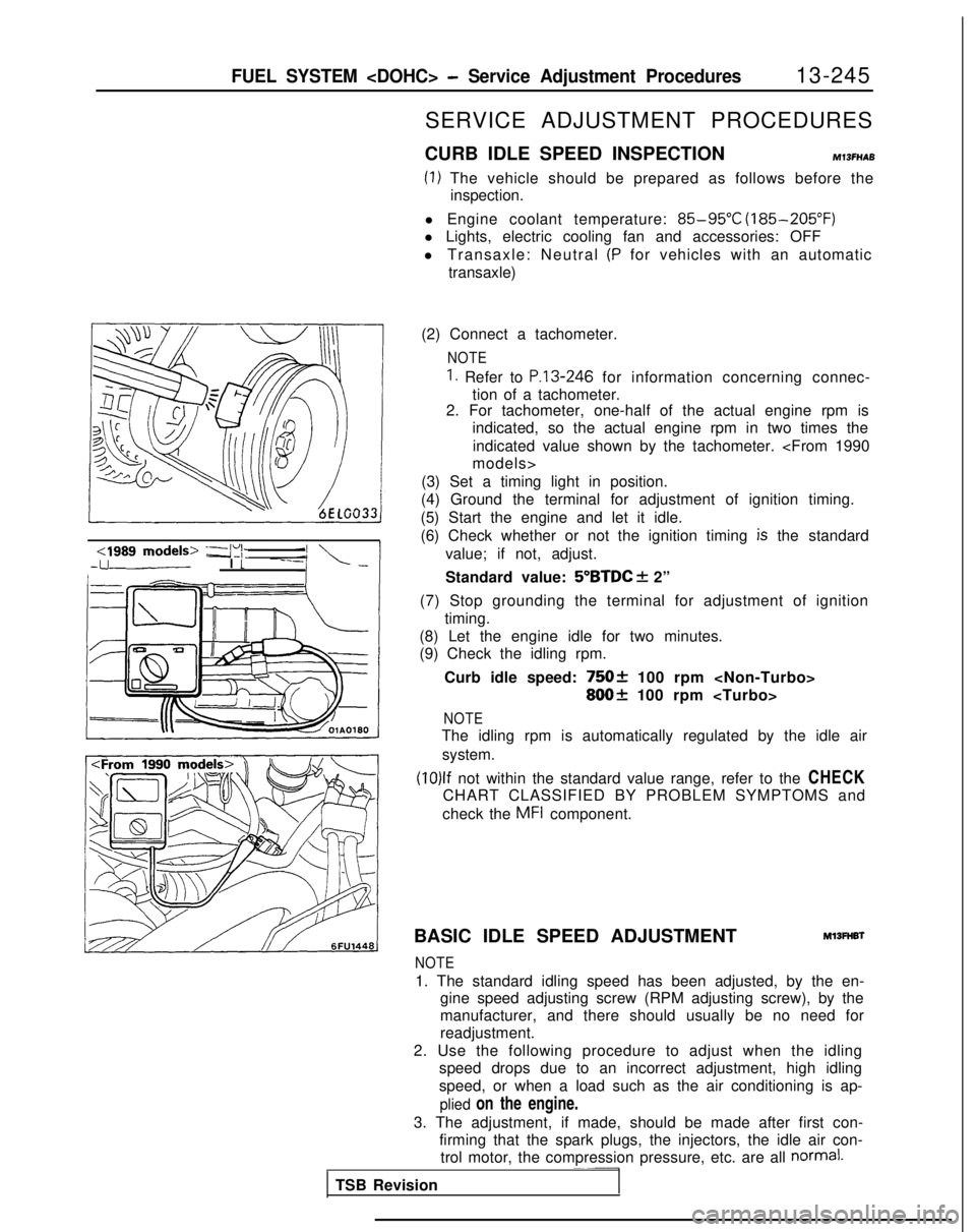
(2) Connect a tachometer.
NOTE
1. Refer to P.13-246 for information concerning connec-
tion of a tachometer.
2. For tachometer, one-half of the actual engine rpm is
indicated, so the actual engine rpm in two times the
indicated value shown by the tachometer.
models>
(3) Set a timing light in position.
(4) Ground the terminal for adjustment of ignition timing.
(5) Start the engine and let it idle.
(6) Check whether or not the ignition timing
is the standard
value; if not, adjust.
Standard value:
5”BTDC f 2”
(7) Stop grounding the terminal for adjustment of ignition timing.
(8) Let the engine idle for two minutes.
(9) Check the idling rpm.
Curb idle speed:
75Ok 100 rpm
800+ 100 rpm
NOTE
The idling rpm is automatically regulated by the idle airsystem.
(10)lf not within the standard value range, refer to the CHECK
CHART CLASSIFIED BY PROBLEM SYMPTOMS and
check the
MFI component.
BASIC IDLE SPEED ADJUSTMENT
Ml3FHBl
NOTE
1. The standard idling speed has been adjusted, by the en- gine speed adjusting screw (RPM adjusting screw), by the
manufacturer, and there should usually be no need for
readjustment.
2. Use the following procedure to adjust when the idling speed drops due to an incorrect adjustment, high idling
speed, or when a load such as the air conditioning is ap-
plied on the engine.
3. The adjustment, if made, should be made after first con- firming that the spark plugs, the injectors, the idle air con-trol motor, the compression pressure, etc. are all
normal.~~-
TSB Revision
Page 390 of 1273
13-248FUEL SYSTEM - Service Adjustment Procedures
(8) Switch OFF the ignition switch.
(9) If the scan tool was not used, disconnect the jumper wire from the diagnostic test mode control terminal. (10)Disconnect
the jumper wire from the terminal for adjust-
ment of ignition timing, and return the connector to its
original condition.
(11
)Start the engine again and let it run at idle speed for about
ten minutes; check to be sure that the idling condition is
normal.
THROTTLE BODY (THROTTLE VALVE AREA)
CLEANING
Ml3ACL
(1) Start the engine and warm it up until the temperature of the engine coolant reaches
80°C (176°F) or higher; then stop
the engine.
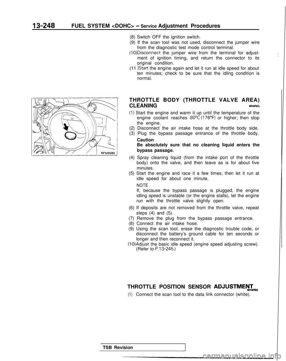
(2) Disconnect the air intake hose at the throttle body side.
(3) Plug the bypass passage entrance of the throttle body.
Caution
Be absolutely sure that no cleaning liquid enters the
bypass passage.
(4) Spray cleaning liquid (from the intake port of the throttle body) onto the valve, and then leave as is for about five
minutes.
(5) Start the engine and race it a few times; then let it run at
idle speed for about one minute.
NOTE
If, because the bypass passage is plugged, the engine
idling speed is unstable (or the engine stalls), let the engine
run with the throttle valve slightly open.
(6) If deposits are not removed from the throttle valve, repeat steps (4) and (5).
(7) Remove the plug from the bypass passage entrance.
(8) Connect the air intake hose.
(9) Using the scan tool, erase the diagnostic trouble code, or disconnect the battery’s ground cable for ten seconds or
longer and then reconnect it. (lO)Adjust
the basic idle speed (engine speed adjusting screw).
(Refer to
P.13-245.)
THROTTLE POSITION SENSOR ADJUSTMEyTmEE
(1)Connect the scan tool to the data link connector (white).
TSB Revision
Page 393 of 1273
Page 397 of 1273
FUEL SYSTEM - On-Vehicle Inspection of MFI Components13-255
COMPONENTS INSPECTION PROCEDURE-
Using Scan ToolMlsYsAGa
Refer to P.13-41.
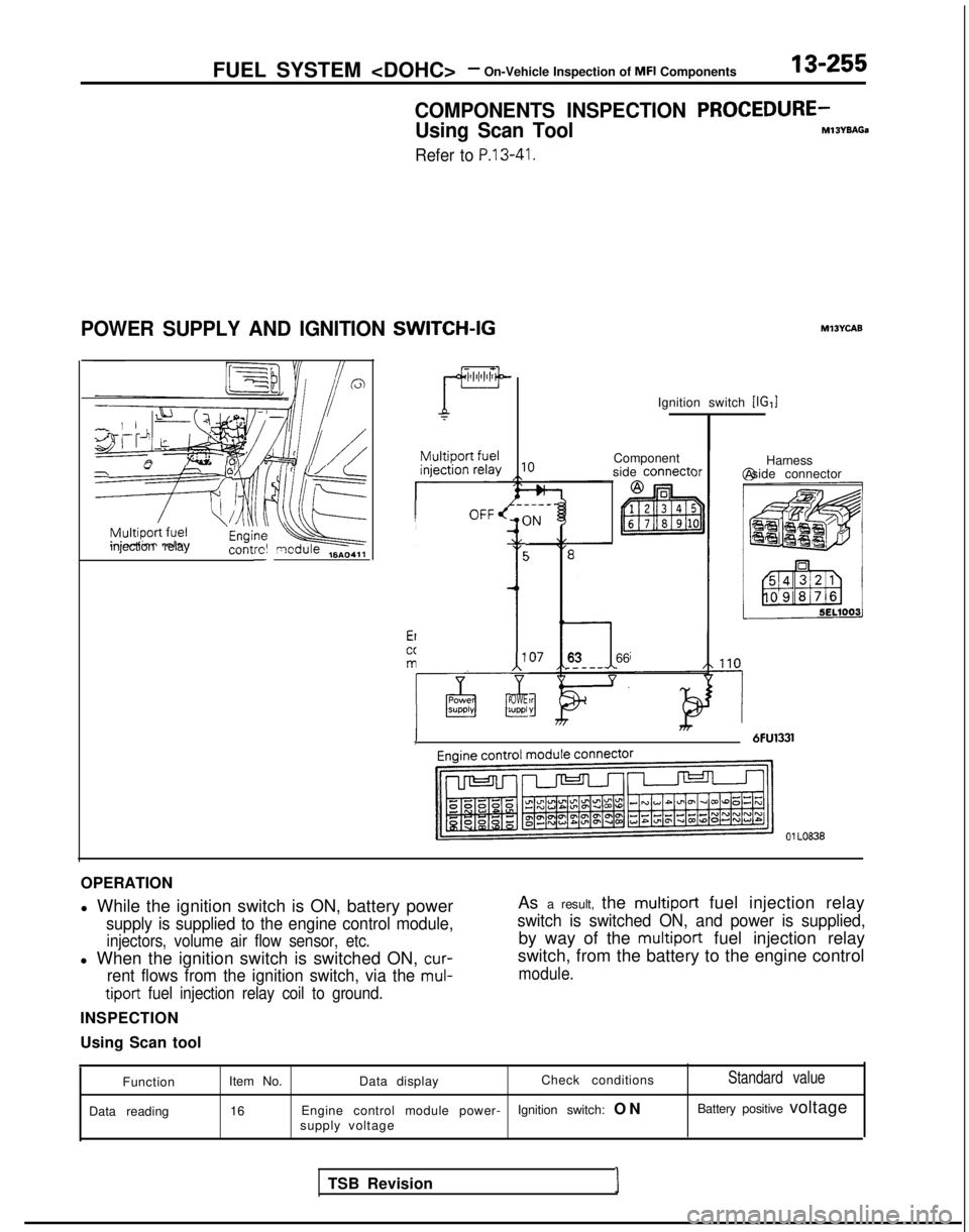
POWER SUPPLY AND IGNITION SWITCH-IG
zT=f?Qjkeinjection relay
contrc! qcdule ,6A04,,-
----_OFF/ (IN
t5
’ i
4
-
‘OWE;uppl-
Ignition switch [IG,]
Component
side
connect<
763 66.----
1 6FU1331, )r
Ml3YcAB
Harness
@ side connector
01 LO838
OPERATION
l While the ignition switch is ON, battery power
supply is supplied to the engine control module,
injectors, volume air flow sensor, etc.
l When the ignition switch is switched ON, cur-
rent flows from the ignition switch, via the mul-
tiport
fuel injection relay coil to ground.
INSPECTION
Using Scan tool As a result, the
multiport fuel injection relay
switch is switched ON, and power is supplied,
by way of the multiport fuel injection relay
switch, from the battery to the engine control
module.
Function
Data reading Item No.
Data display Check conditionsStandard value
16
Engine control module power- Ignition switch: O
N
Battery positive voltage
supply voltage
TSB Revision I
Page 401 of 1273
FUEL SYSTEM -On-Vehicle lnwection of MFI Components13-259
INSPECTION
Using Scan tool
Actuator test
Item No.
07
Actuation1 Inspection conditions 1 Descriotion1 Normal condition
Actuates fuel . Engine cranking
Hold the return hose Pulsation can be felt.pump, circu-. Fuel pump forcedbetween two fingerslating fuel.
activation so as to feel the
The inspectionpulsation of the flow-
should be conducted ing of fuel.
for both of the above
conditions. Listen to the pumpPump sound can be
sound at a place near
heard.the fuel tank.
iCTlON
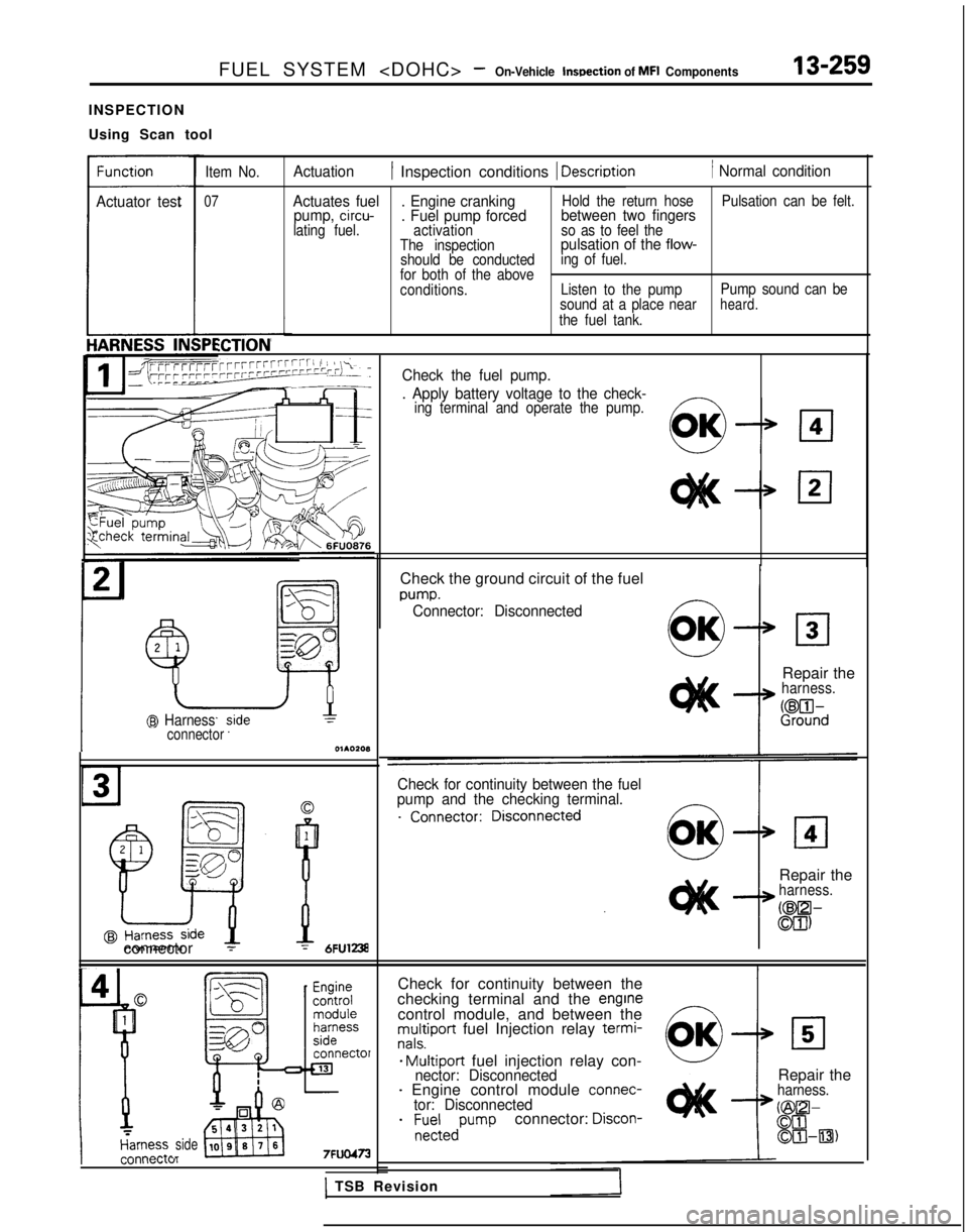
TGrrW’-rTTrrrrrrrrrrrrrrrrrrri 1 SAL TCheck the fuel pump._---__. Apply battery voltage to the check-ing terminal and operate the pump.
@ Harnessconnector
connector 1
sideI_
Check the ground circuit of the fuel
m-m.Connector: Disconnected
Repair theharness.
if?%d
Check for continuity between the fuel
pump and the checking terminal.
Repair theharness.
CW-
Ml)
Check for continuity between the
checking terminal and the enginecontrol module, and between themultiport fuel Injection relay termi-nals.
* Multiport fuel injection relay con-nector: Disconnected- Engine control module connec-tor: Disconnected
- ;~-:edPumpconnector: Discon-
Repair theharness.
@O-00OIHl3)
1 TSB Revision
Page 404 of 1273
13-262FUEL SYSTEM - On-Vehicle Inspection of MFI Components
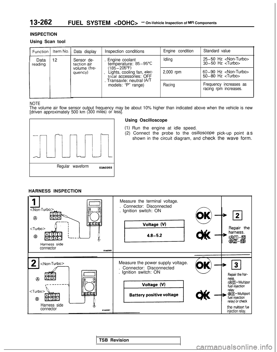
INSPECTION
Using Scan tool
1 Data 12reading
L
Data displayInspection conditions
Sensor de-. Engine coolanttection airtemperature: 85-95°Cvolume (fre-(185-205°F)quency) .Lights, cooling fan, elec-trical accessories: OFF. Transaxle: neutral (PJTmodels: “P” range)
Engine condition
Idling
2,000 rpm
Racing
Standard value 25-50
Hz 30-50 Hz
60-90 Hz 50-80 Hz
Frequency increases as
racing rpm increases.
NOTEThe volume air flow sensor output frequency may be about 10% higher than\
indicated above when the vehicle is new
[driven approximately 500 km(300 miles) or less].
i
Regular waveform03AO203
HARNESS INSPECTION Using Oscilloscope
(1) Run the engine at idle speed.
(2) Connect the probe to the osilloscope
pick-up point as
shown in the circuit diagram, and check the wave form.
Measure the terminal voltage.
. Connector: Disconnected
. Ignition switch: ON
connectorOlMaa
Measure the power supply voltage.
. Connector: Disconnected
. Ignition switch: ON
Harness side
connectorthe multiport fueinjection relay.
TSB Revision
Page 406 of 1273
13-264FUEL SYSTEM - On-Vehicle Inspection of MFI Components
OPERATION
l The intake air temperature sensor functions to
convert the temperature of the air (intaken to the
engine) to voltage, and to input that voltage (as
signals) to the eingine control module. The en-
gine control module, based upon those signals,
then corrects the amount of fuel injection, etc.
lThe 5V power supply within the engine control
module is supplied, by way of the resistance
within the unit, to the intake air temperature
sensor; it passes through the intake air temper-
ature sensor, which is a type of resistor, and is
grounded at the engine control module.
Note that the resistance of the intake air
temperaturesensor decreases when the
temperature of the intake air increases.
* The intake air temperature sensor terminal
voltage becomes higher when the resistance of
the intake air temperature sensor increases, and becomes lower when the resistance decreases.
Consequently, the intake air temperature sensor
terminal voltage varies in accordance with the
temperature of the intake air, becoming lower
when the temperature of the intake air
in-
creases.
TROUBLESHOOTING HINTS
Because the intake air temperature sensor detects
the temperature of the intake air in the air cleaner, it
indicates a temperature different than the tempera-
ture of the outside air when the engine is running.
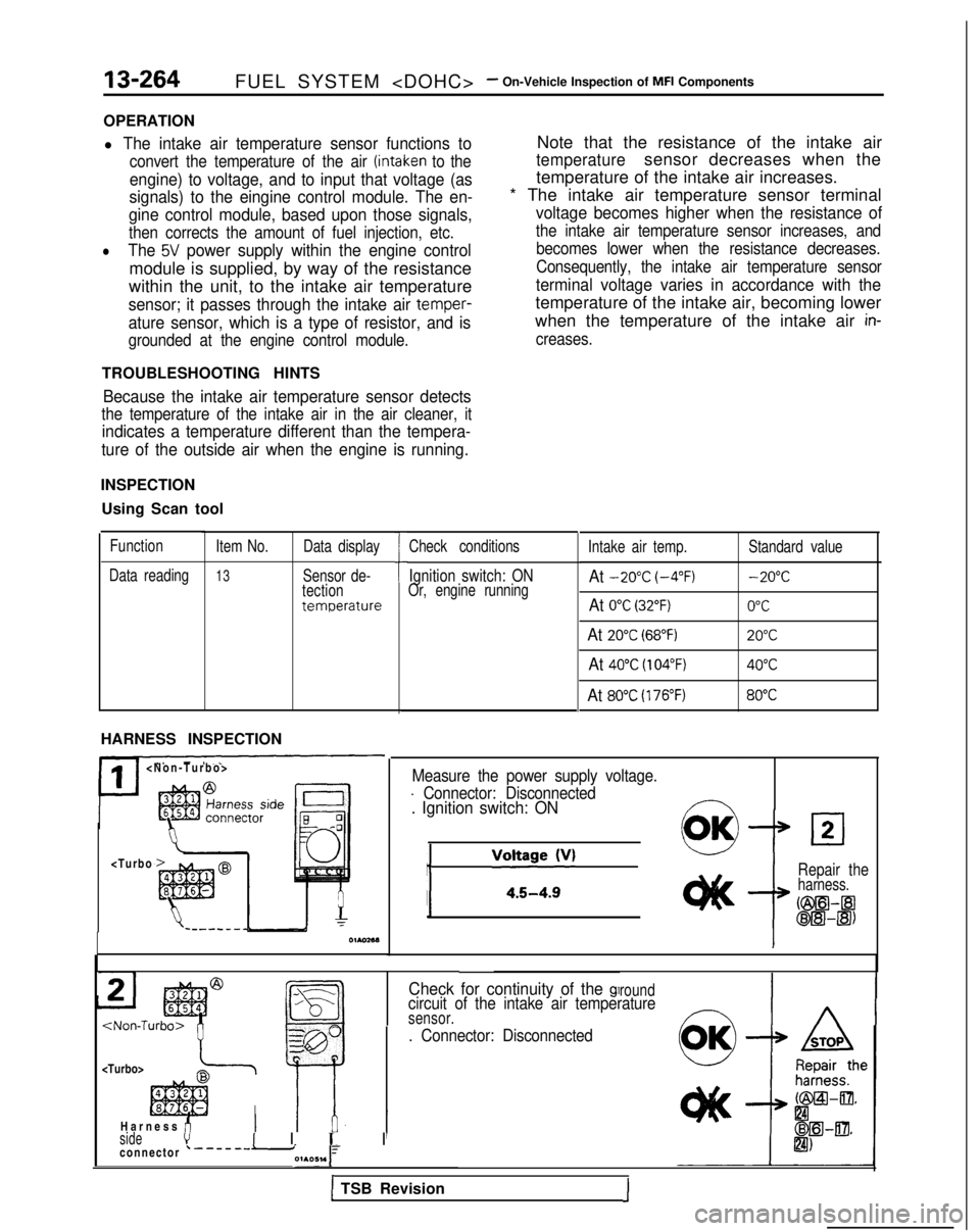
INSPECTION
Using Scan tool
Function
Data reading Item No.
13
Data display
Sensor de-
tection
temperature
HARNESS INSPECTION
II
>
7 7
h
I
Check conditions
Ignition switch: ONOr, engine running
Intake air temp.At -20°C (-4°F)
At 0°C (32°F)
At 20°C (68°F)
At 40°C (104°F)
At 80°C (176°F)
Standard value -20°C
0°C
20°C
40°C
80°C
Measure the power supply voltage.
- Connector: Disconnected. Ignition switch: ON
j
/‘“:;~~~v’0OKLl2
Repair theharness.
Cm--a
oE!l-@)
Check for continuity of the glroundcircuit of the intake air temperaturesensor.
. Connector: Disconnected
I
sidevI I 1~ I
I
Harness fi
connector ‘-------i01A051.1
1 TSB Revision1