Page 277 of 1273
FUEL SYSTEM
VALVE> -Service Adjustment Procedures13-135
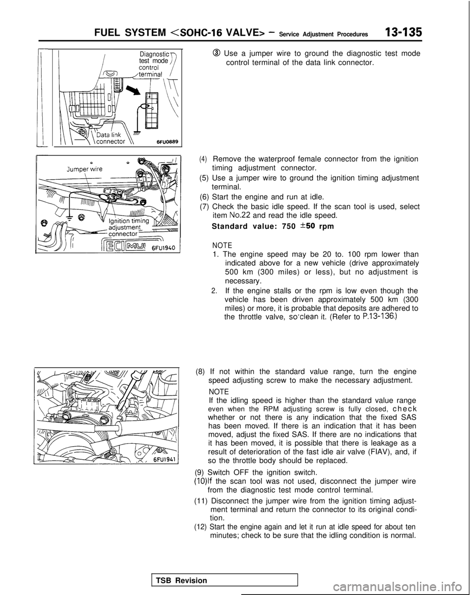
Diagnostictest mode@ Use a jumper wire to ground the diagnostic test mode
control terminal of the data link connector.
TSB Revision
(4)Remove the waterproof female connector from the ignition
timing adjustment connector.
(5) Use a jumper wire to ground the ignition timing adjustment terminal.
(6) Start the engine and run at idle.
(7) Check the basic idle speed. If the scan tool is used, select item
No.22 and read the idle speed.
Standard value: 750
*50 rpm
NOTE
1. The engine speed may be 20 to. 100 rpm lower than indicated above for a new vehicle (drive approximately
500 km (300 miles) or less), but no adjustment is
necessary.
2.If the engine stalls or the rpm is low even though the
vehicle has been driven approximately 500 km (300 miles) or more, it is probable that deposits are adhered to
the throttle valve, so’clean
it. (Refer to
P.13-136.)
(8) If not within the standard value range, turn the engine
speed adjusting screw to make the necessary adjustment.
NOTE
If the idling speed is higher than the standard value range
even when the RPM adjusting screw is fully closed, chec
k
whether or not there is any indication that the fixed SAS has been moved. If there is an indication that it has been
moved, adjust the fixed SAS. If there are no indications that
it has been moved, it is possible that there is leakage as a
result of deterioration of the fast idle air valve (FIAV), and, if
so the throttle body should be replaced.
(9) Switch OFF the ignition switch. (lO)lf
the scan tool was not used, disconnect the jumper wire
from the diagnostic test mode control terminal.
(11) Disconnect the jumper wire from the ignition timing adjust- ment terminal and return the connector to its original condi-
tion.
(12) Start the engine again and let it run at idle speed for about ten\
minutes; check to be sure that the idling condition is normal.
Page 281 of 1273
FUEL SYSTEM - ?::;:r%t~pection Of MF’13439
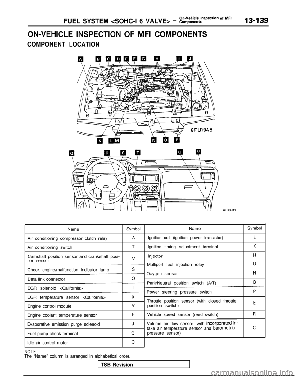
ON-VEHICLE INSPECTION OF MFI COMPONENTS
COMPONENT LOCATION
6FUO843
Name Symbol NameSymbol
Air conditioning compressor clutch relay A
Ignition coil (ignition power transistor)
L
Air conditioning switchTIgnition timing adjustment terminalK
Camshaft position sensor and crankshaft posi- InjectorHMtion sensor- Multiport fuel injection relayU
Check engine/malfunction indicator lampS- Oxygen sensorN
Data link connectorQ- Park/Neutral position switch (A/T)6
EGR solenoid I- Power steering pressure switchP
EGR temperature sensor 0
Throttle position sensor (with closed throttle
position switch)
EEngine control modulev
Engine coolant temperature sensorFVehicle speed sensor (reed switch)R
Evaporative emission purge solenoidJVolume air flow sensor (with incorporated,in-
take air temperature sensor and barometncC
Fuel pump check terminalGpressure sensor)
Idle air control motor
D
NOTEThe “Name” column is arranged in alphabetical order. TSB Revision
Page 283 of 1273
FUEL SYSTEM - ::ii,,k:t~pection Of MF’13-141
6FuO984
Crankshaft position sensor
\\6FU193~
I(7-T
I;.’ E
,/ii
;
i
; ~&qqLk~
)
’ [,,“\,k@$&b;,,,“\
I’
/ \, pQi, >{,
1; /
‘\l>,
/\\\6FUO8Oi
,<,$+$GgT
z Jp$j&& ‘\
,
“2$---8%\.35 Fqp2; ,I <,, cLTgg.&~.
,D~~,
1sl ) g , a&&iI& I.“: :
(;-omd!gs?~ 5, gt : .“*I-- L l2,, m ‘IFiTb;qF
/Check engine/malfunction
indicator lamp68b.0093
B :iG i 1
,i mIl-
11
’ 0_;
3
(1P
I”;l-i-yCL, ,\i / ,---_ /
’ - ’ +-+j$p2E~~;:c9h
/ /I----4 ) Jj 1 1’ 6FU0656
68mosJ
I(>/
!,ij”_II. .:a L-2__--. ~-~-Air conditioning I~.~ ~..
LT. --..-6FUO64!
TSB Revision
Page 292 of 1273
On-Vehicle Inspection of MFI
13450FUEL SYSTEM
VALVE> - Components
VOLUME AIR FLOW SENSOR
Intake air amountWsec)16245
1
@ Componentsideconnectof
Multiport
fuel
injection relay
/ohme air flow sensor/\2/\-
@Harness side
Isv xI 6FU1952
OPERATION TROUBLESHOOTING HINTSRefer to
P.13-49.
INSPECTION
Using Scan Tool
Item No.
12
Data displayInspection conditions Engine condition
Standard value
Sensor de- . Engine coolant Idle speed
18-44 Hz
tection airtemperature: 85-95°C
volume (fre- (185-205°F)
quency)
. Lights, cooling fan, elec-
2,000 rpm64-l 04 Hz tricaI
accessories: OFF
Transaxle: neutral
(PJTmodels: “P” range)RacingFrequency in-
creases as racing rpm increases.
NOTE
The volume air flow sensor output frequency may be about 10% higher than\
indicated above when the vehicle is new[driven approximately 500 km (300 miles) or less].
TSB Revision
1
Page 300 of 1273
On-Vehicle Inspection of MFI
13-158FUEL SYSTEM (SOHC-16 VALVE> - Components
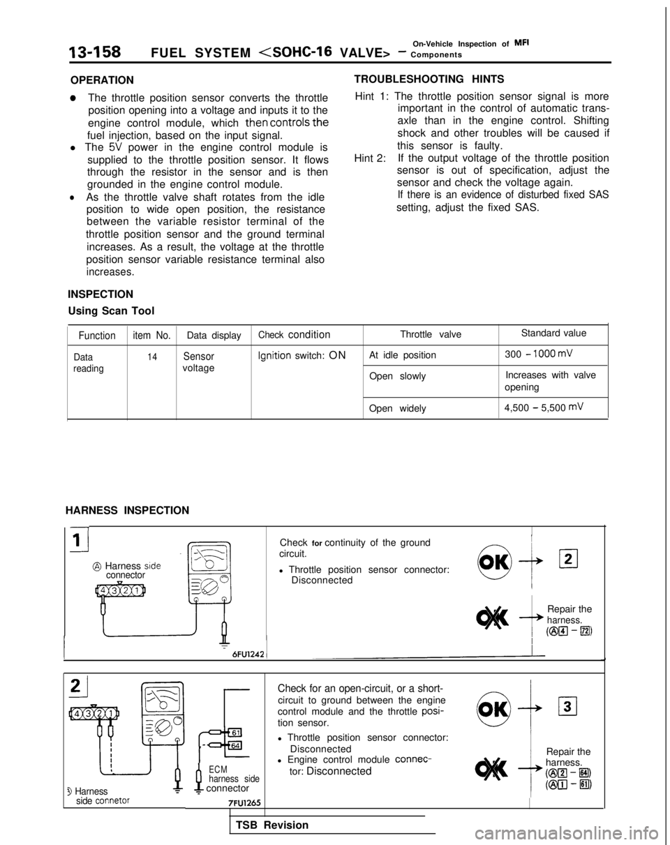
OPERATION
aThe throttle position sensor converts the throttle position opening into a voltage and inputs it to the
engine control module, which
then controls
the
fuel injection, based on the input signal.
l The
5V power in the engine control module is
supplied to the throttle position sensor. It flows
through the resistor in the sensor and is then
grounded in the engine control module.
lAs the throttle valve shaft rotates from the idle position to wide open position, the resistancebetween the variable resistor terminal of the
throttle position sensor and the ground terminal increases. As a result, the voltage at the throttle
position sensor variable resistance terminal also
increases.
INSPECTION
Using Scan Tool TROUBLESHOOTING HINTS
Hint 1: The throttle position sensor signal is more important in the control of automatic trans-
axle than in the engine control. Shifting
shock and other troubles will be caused if
this sensor is faulty.
Hint 2: If the output voltage of the throttle position
sensor is out of specification, adjust the
sensor and check the voltage again.
If there is an evidence of disturbed fixed SAS
setting, adjust the fixed SAS.
Function item No.Data displayCheck conditionThrottle valve Standard value
Data14Sensor Ignition
switch: ON At idle position 300 - 1000 mV
readingvoltage
Open slowlyIncreases with valve
opening
Open widely 4,500
- 5,500 mV
HARNESS INSPECTION
-
i1
@ Harness sideconnector
Check for continuity of the ground
circuit.
l Throttle position sensor connector: Disconnected
Repair the
harness.
(ml-m
3 Harnessside connetor
P
ECMharness sidef connector
Check for an open-circuit, or a short-
circuit to ground between the engine
control module and the throttle posi-
tion sensor.
l Throttle position sensor connector:
Disconnected
l Engine control module connec-
tor: Disconnected Repair the
harness. @El
- El)
(@III-ElII
TSB Revision
Page 304 of 1273
On-Vehicle Inspection of MFI13-162FUEL SYSTEM (SOHC-16 VALVE> - Components
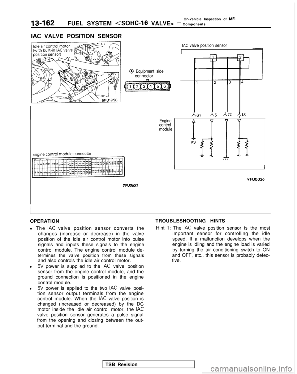
IAC VALVE POSITION SENSOR
@
Equipment side
connector 7FlJO653
Enginecontrol
module
IAC valve position sensor
h61 A\5
A72 Al8
% 5v
I
9FUOO26
OPERATION
l The
IAC valve position sensor converts the
changes (increase or decrease) in the valve
position of the idle air control motor into pulse
signals and inputs these signals to the engine
control module. The engine control module de-
termines the valve position from these signals and also controls the idle air control motor.
l
5V power is supplied to the IAC valve position
sensor from the engine control module, and the
ground connection is positioned in the engine
control module.
l
5V power is applied to the two IAC valve posi-
tion sensor output terminals from the engine control module. When the
IAC valve position is
changed (increased or decreased) by the DC motor inside the idle air control motor, the
IAC
valve position sensor generates a pulse signal
from the opening and closing between the out-
put terminal and the ground. TROUBLESHOOTING HINTS
Hint 1: The
IAC valve position sensor is the most
important sensor for controlling the idle
speed. If a malfunction develops when the
engine is idling and the engine load is varied
by turning the air conditioning switch to ON
and OFF, etc., this sensor is probably defec-
tive.
TSB Revision
Page 305 of 1273
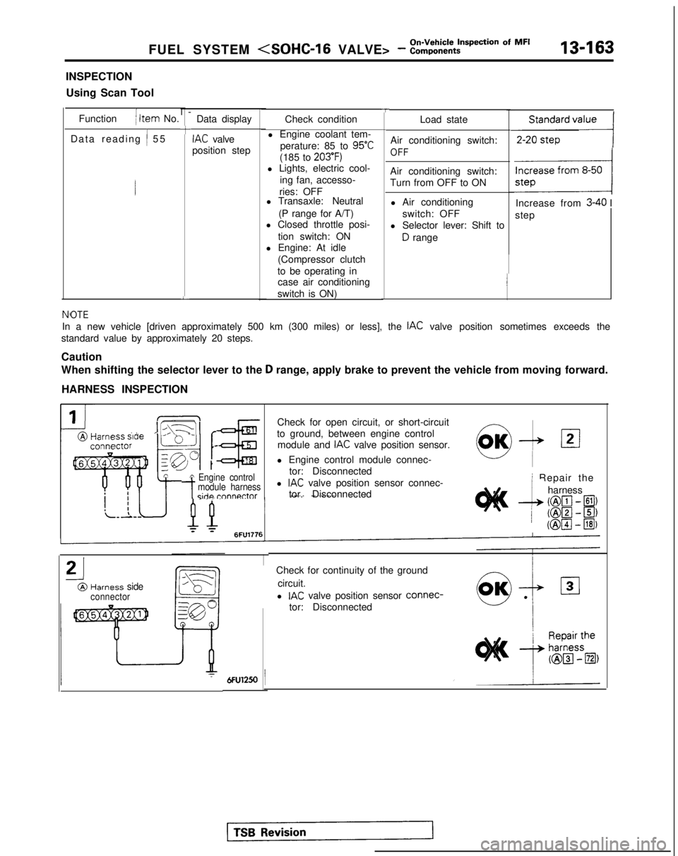
FUEL SYSTEM - :::,:k:t?=tiion Of MF’13-163
INSPECTION
Using Scan Tool
Function
( Item No.
Data reading
/ 5
5
l-
+
L
Data display
IAC valve
position step
TCheck condition
l Engine coolant tem- perature: 85 to
95°C
(185 to 203’F)l Lights, electric cool- ing fan, accesso-
ries: OFF
l Transaxle: Neutral
(P range for A/T)
l Closed throttle posi-
tion switch: ON
l Engine: At idle
(Compressor clutch
to be operating in case air conditioning
switch is ON) Load state
Air conditioning switch:
OFF
Air conditioning switch:
Turn from OFF to ON l Air conditioning switch: OFF
l Selector lever: Shift to
D range
,,,,,,,,,I
Increase from 3-40 I
step
NfOTE
In a new vehicle [driven approximately 500 km (300 miles) or less], th\
e IAC valve position sometimes exceeds the
standard value by approximately 20 steps.
Caution
When shifting the selector lever to the
D range, apply brake to prevent the vehicle from moving forward.
HARNESS INSPECTION
IIL\-11 r@Harm ” ’ -conna
tA Engine control
-tmodule harnessside rnnnnctor
Check for open circuit, or short-circuit
to ground, between engine control module and
IAC valve position sensor.
l Engine control module connec- tor: Disconnected
l
IAC valve position sensor connec-
tor. Disconnected
21
@Harness sideconnector
0,OK-& 121
i Repair the
--L
harness
(@lcl- El)
/ ml-~) (@pJ
- @I)
Check for continuity of the ground
circuit.
l
IAC valve position sensor connec-
tor: Disconnected
Page 318 of 1273
13-176FUEL SYSTEM - ::i$%%-ti=pection Of MF’
1
@ Harnesssrde connector
7FUOSO5
Measure the impressed voltage./\1A
l Power steering pressure switch
connector: Disconnected
l Engine control module connec-
tor: Connected
l Ignition switch: ON
Voltage
04
1 modul
e
J
AIR CONDITIONING SWITCH AND A/C COMPRESSOR CLUTCH RELAY
hl13YRABl
ii++----- ,L’AI:
Air conditionino1 switch -
‘A //A\‘A /,,--.l, ,+q‘\
\\Wj i EYAJ26FUO645
Air conditioning
compresso
r
clutch
relav
~-1 6FUO612
Engine control module connector
Sub fusible link
TSB Revision Air conditioning
1
@ m i”“:F$
1
Engine control module ,
I7FUO653
-
,4,
g:2
[
22
Auto compressorcontrol unit
6
2 Dual pressure
I switch 3N
3N
1
1
Air conditioningOFFengine COOlant,^N temperature
2switch
11
5
6FU145.7
OPERATION
TROUBLESHOOTING HINTS INSPECTION
Using Scan Tool Refer
to P.13-83.