Page 85 of 1273

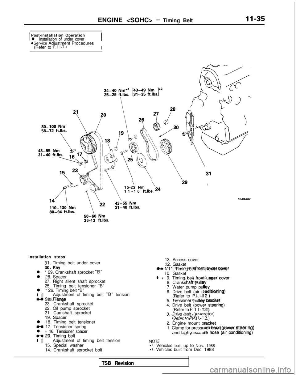
ENGINE - Timing BeltII-35
IPost-installation Operationl installation of under coverIaService Adjustment Procedures
(Refer to P.ll-7.)I 50-60
Nm36-43 ftlbs.
31
\\15-22 Nm
11-16 ft.lbs. 24
01 A0437
30. KevIL. -I"..--+A ‘IIT:m;nn halt fmnf lower cover
Installation steps
31. Timing belt under cover
30. Key
l * 29. Crankshaft sprocket
“B”l 28. Spacer 27. Right silent shaft sprocket
25. Timing belt tensioner “B”
l * 26. Timing belt “B”
l 4Adjustment of timing belt “B” tensionl * 24. Flange23. Crankshaft sprocket
22. Oil pump sprocket
21. Camshaft sprocket
19. Spacer
l 18. Timing belt tensioner
~~ 17. Tensioner springl + 16. Tensioner spacer++ 20. Timing beltl 4Adjustment of timing belt tension
15. Special washer 14. Crankshaft sprocket bolt
tic 24. Flanae
, UtiIL , , WI ,t upper cover!hcaft n, dlqy
lb. :;d)rtroning)
\..“.w.
.-c
T-mrinnar r
nliny bracket
er steering)1 2.)
19. Spacer
++ 20. Timing belt13. Access cover
12. Gasket
l +
11. Timing belt front lower cover10. Gasketl +9. Timing belt front upper cover 8. Crankshaft pulley
7. Water pump pulley
6. Drive belt (air conditioning) (Refer to P.l l-l 2.)
5. Tensioner pulley bracket
4. Drive belt (power steering)
(Refer to
P. 1 l-l 2.)
3. Drive belt (generator) (Refer to P.l l-l 2.)
2. Engine mount bracket 1. Clamp for pressure hose (power steering)
and high pressure hose (air conditioning)
NOTE*I: Vehicles built up to N O
V. 1988
+2: Vehicles built from Dec. 1988 lrator)
U. Vll”” ““SC \y”v’ulRpfcw tn P 1 l-l
2.)
racket
NOT=
ure hose (power steering)
s-4, I” I “..J’I p.. .#““.are hose (air conditioning)
TSB Revision
TSB Revision
Page 92 of 1273
11-42
ENGINE - Timing Belt
TIMING BELT
REMOVAL AND INSTALLATION
MIlKA-A
Pre-removal Operation
l Removal of under cover
8-10 Nm6-7 ftlbs.
4
’‘\ 50-65
Nm
36-47
ft.lbs.\
IO-12 Nm7-9 ftlbs.
\
\
ft.lbs.’3Q ’23-27 Nm
17-20 ft.lbs.
Removal steps
1.
2.
Clamp for
pressure
hose (power steering)
and high pressure hose (air conditioning) Engine mount bracket
Drive belt (generator) Drive belt (power steering)
Tensioner pulley bracket Drive belt (air conditioning)
Water pump pulley Crankshaft pulley
Timing belt front upper cover
Timing belt front lower cover
Auto tensioner
Timing belt OlA0677
::5.6.
i:9.10.11.
12.
13.14.Tensioner pulley
Tensioner arm
15.
::16.
17.
18.
19.
20.
21.
22.
4*23.
24.
25.
27.
28.
29.
idle pulley
Camshaft sprocket
Oil pump sprocket
Crankshaft sprocket bolt
Special washer Crankshaft sprocket
FlangeTiming belt tensioner “B”
Timing belt “B”
Right silent shaft sprocket Spacer
Kky
Engine support bracket bolt
Timing belt under cover
P
TSB Revision
Page 93 of 1273

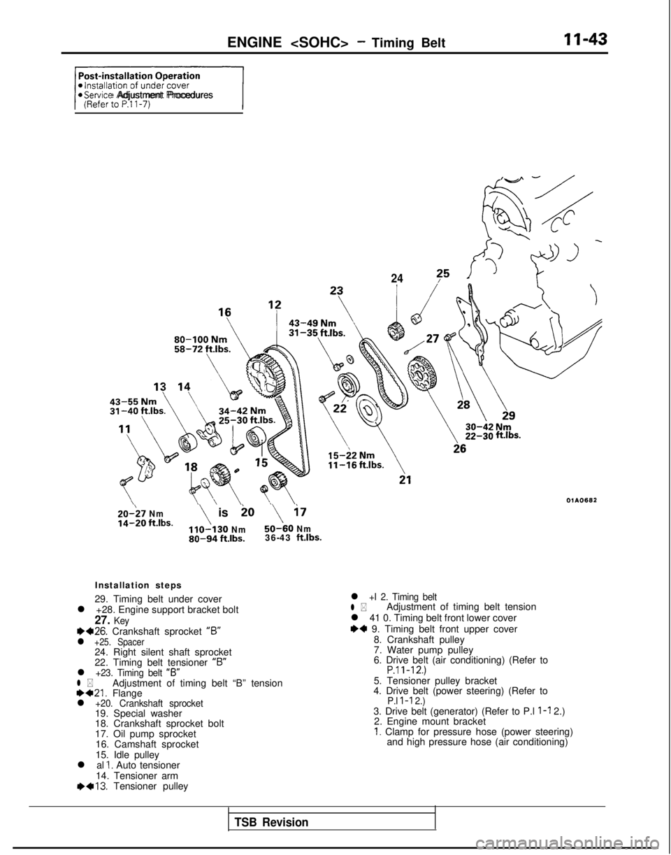
ENGINE - Timing BeltII-43
+/@Service Adjustment Procedures
24?5
20-;7 Nmio
14-20 ft.lbs.\ is\ i7
Nm50-60 Nm80-94 ft.lbs.36-43 ft.lbs.
Installation steps
29. Timing belt under cover
l +28. Engine support bracket bolt
27. Keyea26. Crankshaft sprocket “6”l +25. Spacer24. Right silent shaft sprocket
22. Timing belt tensioner “B”
l +23. Timing belt
“B”l *Adjustment of timing belt “B” tension1)421. Flangel +20. Crankshaft sprocket19. Special washer
18. Crankshaft sprocket bolt
17. Oil pump sprocket
16. Camshaft sprocket
15. Idle pulley
l al
1. Auto tensioner
14. Tensioner arm 1)+13.
Tensioner pulley
ftlbs.
OlAO682
l +I 2. Timing beltl *Adjustment of timing belt tension
l 41 0. Timing belt front lower cover
I)+ 9. Timing belt front upper cover 8. Crankshaft pulley
7. Water pump pulley
6. Drive belt (air conditioning) (Refer to
P.ll-12.)5. Tensioner pulley bracket
4. Drive belt (power steering) (Refer to
P.l l-l 2.)3. Drive belt (generator) (Refer to P.l l-l 2.)
2. Engine mount bracket
I. Clamp for pressure hose (power steering) and high pressure hose (air conditioning)
TSB Revision
Page 104 of 1273

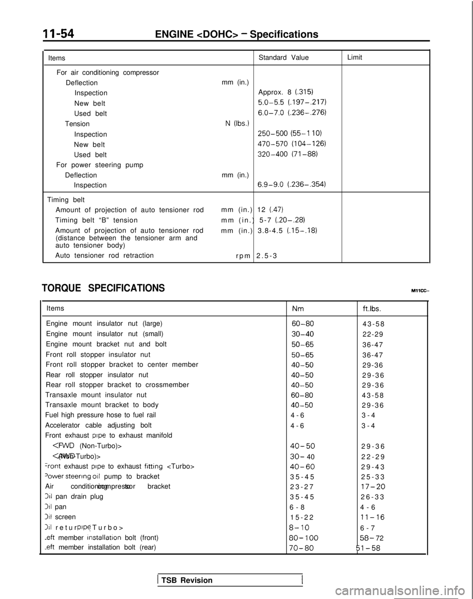
11-54ENGINE - Specifications
Items For air conditioning compressor DeflectionInspection
New belt
Used belt
Tension
Inspection
New belt
Used belt
For power steering pump
DeflectionInspection
Timing belt Amount of projection of auto tensioner rod
Timing belt “B” tension
Amount of projection of auto tensioner rod (distance between the tensioner arm and
auto tensioner body)
Auto tensioner rod retraction Standard Value
mm (in.) Approx. 8
(.315)
5.0-5.5 (.197-,217)
6.0-7.0 (.236-.276)
N (Ibs.)
250-500 (55-l 10)
470-570 (104-126)
320-400 (71-88)
mm (in.)
6.9-9.0 (.236-,354)
mm (in.) 12 (.47)
mm (in.) 5-7 (.20-.28)
mm (in.) 3.8-4.5 (.15-.18)
rpm 2.5-
3
Limit
TORQUE SPECIFICATIONS
Items
Engine mount insulator nut (large)
Engine mount insulator nut (small)
Engine mount bracket nut and bolt
Front roll stopper insulator nut
Front roll stopper bracket to center member
Rear roll stopper insulator nut
Rear roll stopper bracket to crossmember
Transaxle mount insulator nut
Transaxle mount bracket to body
Fuel high pressure hose to fuel rail
Accelerator cable adjusting bolt
Front exhaust
pope to exhaust manifold
(Non-Turbo)> CAWD (Non-Turbo)>
+ont exhaust pope to exhaust fitting
‘ower steerrng 011 pump to bracket
Air conditioning to bracket compressor311
pan drain plug
311 pan
3il screen
111 return (Turbo
>
pope
.eft
member installation
bolt (front)
-eft member installation bolt (rear) Nm
ft.ibs.
60-8043-5
8
30-4022-29
50-6536-47
50-6536-47
40-5029-36
40-5029-3
6
40-5029-3
6
60-8043-5
8
40-5029-3
6
4-6 3-4
4-6 3-4
40-5029-3
6
30- 40
22-2
9
40-6029-4
3
35-45 25-33
23-27
17-20
35-4
5
26-33
6-8 4-6
15-22
11-16
8-106-
7
80-
10058- 72
70-8051-58
MllCC--
( TSB Revision
Page 111 of 1273
ENGINE - Service Adjustment Procedures11-61
DRIVE BELTS TENSION ADJUSTMENT
MllFMBBl
(1) Check that the belts are not damaged.
Power
steering
oil pump
pulley , W
ater
pump
pulley
Tension
pulley
f /
xI J
b
L ‘d
p1 Genkrator
I
Ipulley
Crankshaft
Air
pulley conditioning
compressor
pulley
Spindle Spindle
2Y
\Hook
xi@--
V-ribbed belt
Hook
r
Type BRESET button (2) Apply
100N (22 Ibs.) force to the belt back midwa
y
between the pulleys as shown in the figure, measure the
deflection or, by using a belt-tension gauge, check the
belt’s tension.
Standard value:
Items
For
AKDeflection Approx. 8.05.0-5.56.0-7.0
comDressormm (in.)t.3151(.197-,217) (.236-.276)I
NOTE
There is more than one type of belt-tension gauge (type A and
type
B, for example), so be sure to use the gauge according to
its instructions for use.
1 TSB Revision
Page 112 of 1273

II-62ENGINE - Service Adjustment Procedures
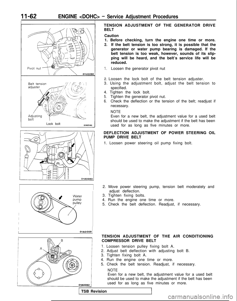
Lock boltTENSION ADJUSTMENT OF THE GENERATOR DRIVE
BELT
Caution
1. Before checking, turn the engine one time or more.
2.If the belt tension is too strong, it is possible that the
generator or water pump bearing is damaged. If the belt tension is too weak, however, sounds of its slip-
ping will be heard, and the belt’s service life will be
reduced.
1.Loosen the generator pivot nut
2. Loosen the lock bolt of the belt tension adjuster.
3. Using the adjustment bolt, adjust the belt tension to
specified.
4. Tighten the lock bolt.
5.Tighten the generator pivot nut.
6.Check the deflection or the tension of the belt; readjust if
necessary.
NOTE
Even for a new belt, the adjustment value for a used belt
should be used to make the adjustment if the belt has been used for as long as five minutes or more.
DEFLECTION ADJUSTMENT OF POWER STEERING OIL
PUMP DRIVE BELT 1. Loosen power steering oil pump fixing bolt.
2. Move power steering pump, tension belt moderately and adjust deflection.
3. Tighten fixing bolts.
4. Run the engine one time or more. 5. Check the belt deflection. Readjust, if necessary.
IIOlA0059
r
TSB Revision TENSION ADJUSTMENT OF THE AIR CONDITIONING
COMPRESSOR DRIVE BELT
1. Loosen tension pulley fixing bolt A.
2. Adjust belt deflection with adjusting bolt B.
3. Tighten fixing bolt A.
4. Run the engine one time or more. 5. Check the belt tension. Readjust, if necessary.
NOTE
Even for a new belt, the adjustment value for a used belt
should be used to make the adjustment if the belt has been
used for as long as five minutes or more.
Page 115 of 1273
ENGINE - Engine Assembly11-65
models>
4-6
Nm
25
18
05AO196
I
23\il4-6 Nm3-4 ftlbs.
12. Connection for engine coolanttemperature switch
13. Connection for oxygen sensor
14. Connection for engine coolant
temperature sensor
15. Connection for engine coolant
temperature gauge unit
16. Connection for air conditioning engine
coolant temperature switch
17. Connection for
IAC motor
18. Connection for closed throttle position switch 19. Connection for fuel injectors
20. Connection for EGR temperature sensor
(California vehicles only)
21. Connection for knock sensor (Turbo)
22. Connection for ignition coil
23. Connection for ignition power transistor
24. Connection for throttle position sensor
25. Connection for crankshaft position sensor
26. Connection for ground cable
27. Control wiring harness
TSB Revision
1
Page 116 of 1273
11-66ENGINE - Engine Assembly
28
29
30
35-45 Nm25-33 ftlbs.
50-65 Nm36-47 ft.lbs.
I
3132
40-50
Nm29-36 ftlbs.
43-56
ft.lbs.
-- .__.. 36-47
ft.lbs.* 54’q
28. z;tFhction for power steering pressure
29. Connection for generator
30. Generator wiring harness clamps
31. Connection for oil pressure switch 4W 1)432.
Connection for power steering oil pump
++ ++33. Connection for air conditioning
compressor
34. Self-locking nut
35. Gasket
36. Bracket
4*37. Engine mount bracket
38. Self locking nut
+e l + 39. Engine assembly
22- 29 ftlbs.c-rurbo>40-60 Nm29- 43 ftlbs.
OlAO405
NOTEFor tightening locations indicated by the l , symbol, firsttighten temporarily, and then make the final tlghtenlng withthe entire weight of the engine applied to the vehicle body.
TSB Revision