Page 1049 of 1273
33B-110 ACTIVE-ELECTRONIC CONTROL SUSPENSION - i=ttbborber
SHOCK ABSORBER ASSEMBLYhl33MA-A[EMOVAL
AND INSTALLATION
1989 models
40-50 Nm
29-36 ft.lbs.
Removal
l *
l *
8-10 Nm
steps
1.Air tube2.O-ring3.Bush4.Actuator connector5.Actuator6. Rear height sensor rod
6
17-26 Nm 9127 ft.lbs;.i
1990 modelsz??
4.8-7.2 Nm
4-5 ftlbs.
\
6 80-100
Nm*
58-72
ft.lbs.*
7. Shock at%orber
upper mounting nuts
8. Shock absorber lower mounting bolts
9. Shock absorber assemblyWA0331
NOTE *: Points marked with an asterisk should first
be tightened
provisionally, then tightened fully when the vehicle is
empty.
SERVICE POINTS OF REMOVALm33hlsN
9. REMOVAL OF SHOCK ABSORBER ASSEMBLY
(1) Jack up the torsional axle and arm assembly and keep it lifted up to some degree.
Caution
1.Always insert a wooden block between the jack receptacle and the axle beam and place the jack
at the centre of the axle beam.
2. Make sure that the jack does not contact the lateral rod.
TSB Revision
Page 1055 of 1273
33B-116 ACTIVE-ELECTRONIC CONTROL SUSPENSION - z%rension
‘3.
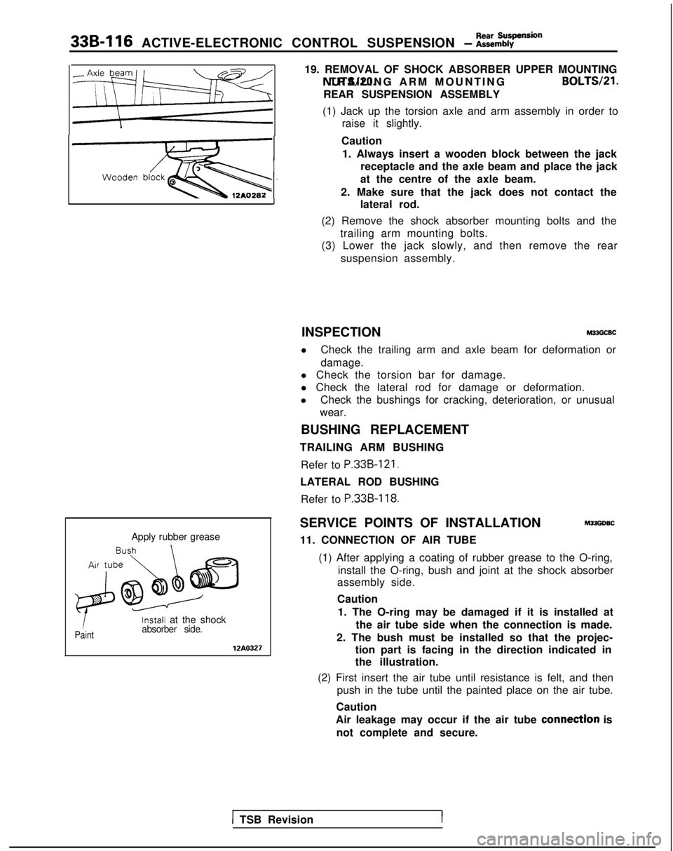
Apply rubber grease
1Paint
Install at the shockabsorber side.
12A0327
19. REMOVAL OF SHOCK ABSORBER UPPER MOUNTING
NUTS/PO. TRAILING ARM MOUNTING
BOLTS/Zl.
REAR SUSPENSION ASSEMBLY
(1) Jack up the torsion axle and arm assembly in order to raise it slightly.
Caution 1. Always insert a wooden block between the jack receptacle and the axle beam and place the jack
at the centre of the axle beam.
2. Make sure that the jack does not contact the lateral rod.
(2) Remove the shock absorber mounting bolts and the trailing arm mounting bolts.
(3) Lower the jack slowly, and then remove the rear
suspension assembly.
INSPECTION
M33GCBC
l Check the trailing arm and axle beam for deformation or
damage.
l Check the torsion bar for damage.
l Check the lateral rod for damage or deformation.
l Check the bushings for cracking, deterioration, or unusual
wear.
BUSHING REPLACEMENT
TRAILING ARM BUSHING
Refer to
P.33B-121.
LATERAL ROD BUSHINGRefer to
P.33B-118.
SERVICE POINTS OF INSTALLATIONM33GDSC
11. CONNECTION OF AIR TUBE
(1) After applying a coating of rubber grease to the O-ring, install the O-ring, bush and joint at the shock absorber
assembly side.
Caution
1. The O-ring may be damaged if it is installed at the air tube side when the connection is made.
2. The bush must be installed so that the projec- tion part is facing in the direction indicated in
the illustration.
(2) First insert the air tube until resistance is felt, and then push in the tube until the painted place on the air tube.
Caution
Air leakage may occur if the air tube
connectYon is
not complete and secure.
1 TSB RevisionI
Page 1059 of 1273
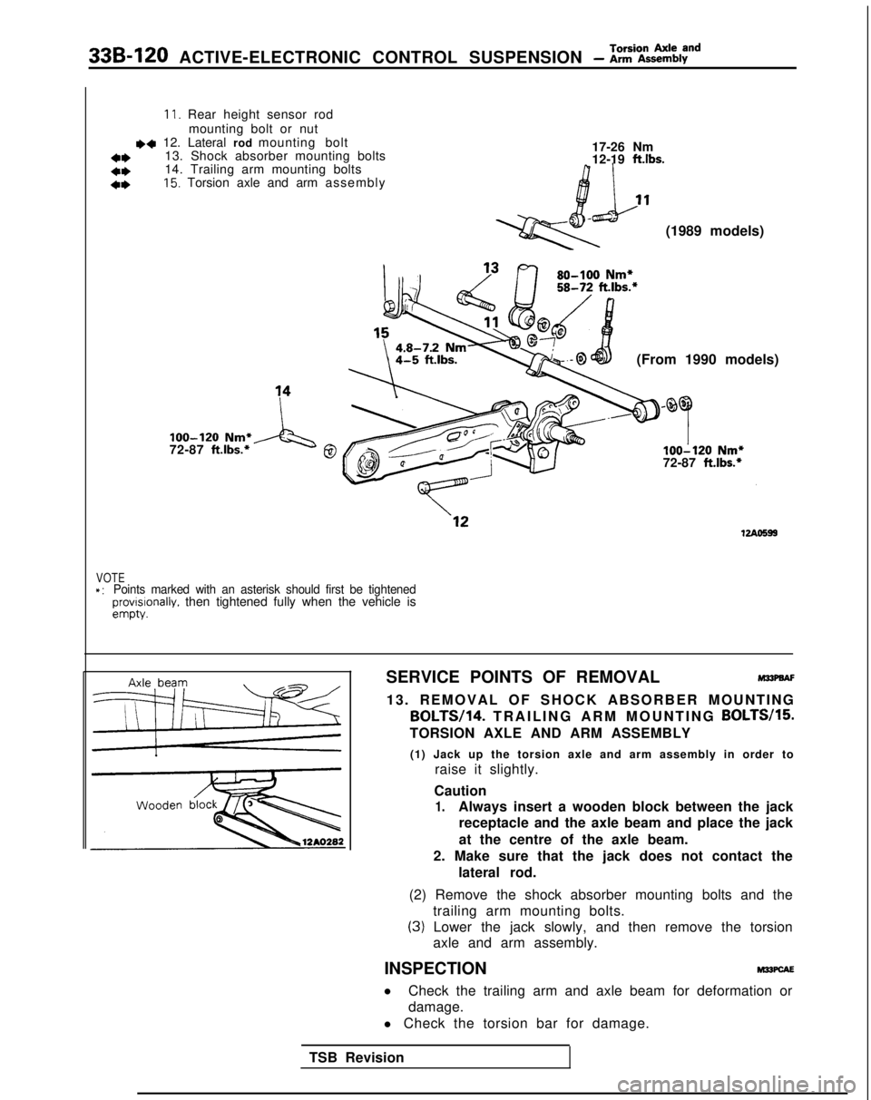
33B-120 ACTIVE-ELECTRONIC CONTROL SUSPENSION - Z%iZky8”d
11. Rear height sensor rodmounting bolt or nut
~~ 12. Lateral rod mounting bolt
13. Shock absorber mounting bolts 17-26 Nm
a*12-19 ftlbs.*I)14. Trailing arm mounting bolts
4*15. Torsion axle and arm assembl
y
(1989 models)
(From 1990 models)
loo-120 Nm*
72-87 ft.lbs.*A‘g0loo-120 Nm*
72-87 ft.lbs.*
VOTE*:Points marked with an asterisk should first be tightenedprovrslonally. then tightened fully when the vehicle isempty.
SERVICE POINTS OF REMOVALM33PaAF
13. REMOVAL OF SHOCK ABSORBER MOUNTING BOLTW14.
TRAILING ARM MOUNTING BOLTW15.
TORSION AXLE AND ARM ASSEMBLY
(1) Jack up the torsion axle and arm assembly in order to raise it slightly.
Caution
1.Always insert a wooden block between the jack receptacle and the axle beam and place the jack
at the centre of the axle beam.
2. Make sure that the jack does not contact the lateral rod.
(2) Remove the shock absorber mounting bolts and the trailing arm mounting bolts.
(3) Lower the jack slowly, and then remove the torsionaxle and arm assembly.
INSPECTION
M22PcAE
l Check the trailing arm and axle beam for deformation or
damage.
l Check the torsion bar for damage.
TSB Revision
Page 1088 of 1273
REAR SUSPENSION - Rear Suspension Assembly
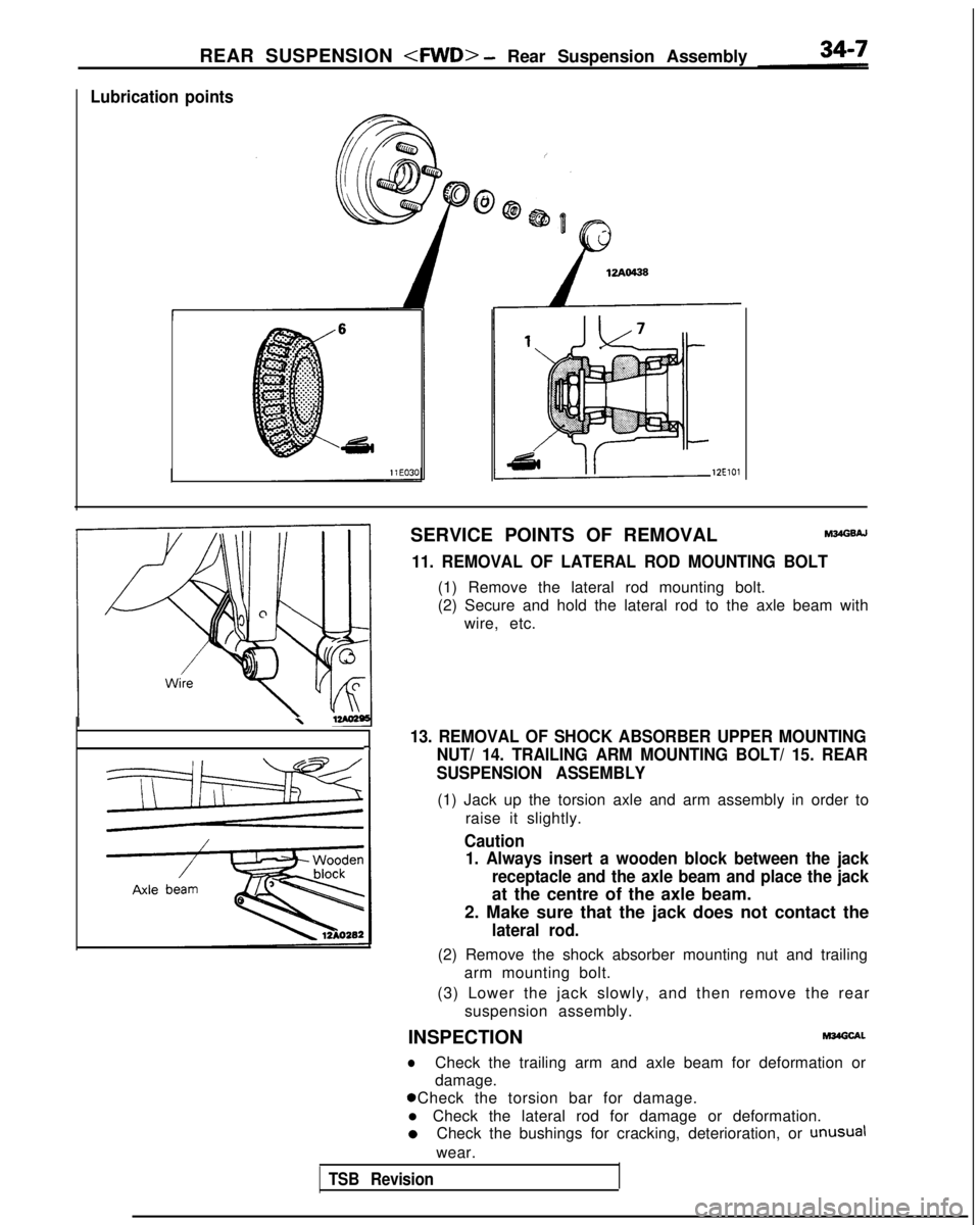
Lubrication points
12ElOl
SERVICE POINTS OF REMOVALM34GsAJ
11. REMOVAL OF LATERAL ROD MOUNTING BOLT
(1) Remove the lateral rod mounting bolt.
(2) Secure and hold the lateral rod to the axle beam with
wire, etc.
\
13. REMOVAL OF SHOCK ABSORBER UPPER MOUNTING-INUT/ 14. TRAILING ARM MOUNTING BOLT/ 15. REAR
SUSPENSION ASSEMBLY
(1) Jack up the torsion axle and arm assembly in order to
raise it slightly.
Caution1. Always insert a wooden block between the jack
receptacle and the axle beam and place the jack
at the centre of the axle beam.
2. Make sure that the jack does not contact the
lateral rod.
(2) Remove the shock absorber mounting nut and trailing arm mounting bolt.
(3) Lower the jack slowly, and then remove the rear suspension assembly.
INSPECTION
M34Glxl.
lCheck the trailing arm and axle beam for deformation or
damage. 0 Check the torsion bar for damage.
l Check the lateral rod for damage or deformation. 0
Check the bushings for cracking, deterioration, or
unusual
wear.
TSB Revision
Page 1092 of 1273
REAR SUSPENSION - Shock Absorber Assemblv
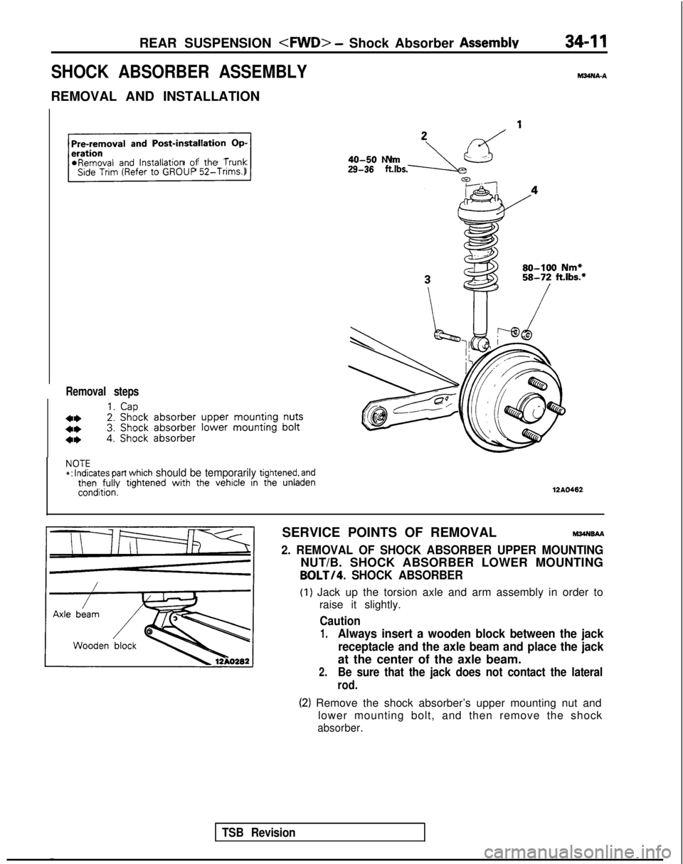
SHOCK ABSORBER ASSEMBLY
REMOVAL AND INSTALLATION
hl34NA-A
Pre-removal
and Post-installation Op-
r
*Removal and lnstallatlon of the TrunkSide Trim (Refer to GROUP
52-Trims.)
Removal steps
1.Cap
4*2. Shock
absorber
upper
mounting
nuts
4*3. Shock
absorber
lower mounting
bolt
4*4. Shock absorber
29-38 .,bs.-JLzd ’40-50 N
m
80-100 Nm*58-72 ft.lbs.*
NOTE*:
Indicates part which should be temporarily tightened, andthen fully
tightened with
the vehicle in the unladencondition.12AO462
TSB Revision
SERVICE POINTS OF REMOVALM34NsAA
2. REMOVAL OF SHOCK ABSORBER UPPER MOUNTING
NUT/B. SHOCK ABSORBER LOWER MOUNTING
BOLT/4. SHOCK ABSORBER
(1) Jack up the torsion axle and arm assembly in order to
raise it slightly.
Caution
1.Always insert a wooden block between the jack
receptacle and the axle beam and place the jack
at the center of the axle beam.
2.Be sure that the jack does not contact the lateral
rod.
(2) Remove the shock absorber’s upper mounting nut and lower mounting bolt, and then remove the shock
absorber.
Page 1097 of 1273
34-16 REAR SUSPENSION - Torsion Axle and Arm Assemblv
L
.ubrication points
12ElOl
SERVICE POINTS OF REMOVALM34PBAC
12. REMOVAL OF SHOCK ABSORBER LOWER MOUNTING
BOLT/ 13. TRAILINGARM
MOUNTINGBOLT
14. TORSION AXLE AND ARM ASSEMBLY
(1) Jack up the torsion axle and arm assembly in order to
raise it slightly.
I
Caution
1.Always insert a wooden block between the jack
receptacle and the axle beam and place the jackh
at the center of the axle beam.
2.Be sure that the jack does not contact the lateral
rod.
(2) Remove the shock absorber’s mounting bolts and the trailing arm mounting bolt.
(3) Lower the jack slowly, and then remove the torsion axle and arm assembly.
INSPECTION
l Check the trailing arm and axle beam for deformation or
damage.
0 Check the torsion bar for damage.
lCheck the bushings for cracking, deterioration, or unusual
wear.
NOTE
For information concerning the replacement of the trailing
arm bushing, refer to
P.34-8.
TSB Revision
Page 1107 of 1273
34-26REAR SUSPENSION - Rear Suspension Assembly
I 412AOlOS
J
TSB Revision
SERVICE POINTS OF REMOVAL
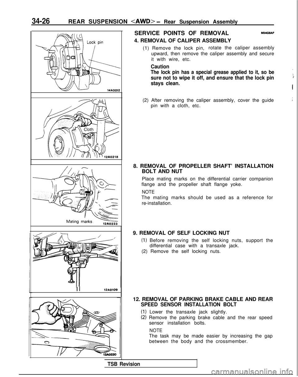
4. REMOVAL OF CALIPER ASSEMBLYM?dGSAP
(1) Remove the lock pin, rotate the caliper assembly
upward, then remove the caliper assembly and secure
it with wire, etc.
Caution
The lock pin has a special grease applied to it, so be
sure not to wipe it off, and ensure that the lock pin
stays clean.
I
(2) After removing the caliper assembly, cover the guide pin with a cloth, etc.
8. REMOVAL OF PROPELLER SHAFT’ INSTALLATION BOLT AND NUT
Place mating marks on the differential carrier companion
flange and the propeller shaft flange yoke.
NOTE
The mating marks should be used as a reference for
re-installation.
9. REMOVAL OF SELF LOCKING NUT
(1) Before removing the self locking nuts, support the differential case with a transaxle jack.
(2) Remove the self locking nuts.
12. REMOVAL OF PARKING BRAKE CABLE AND REAR
SPEED SENSOR INSTALLATION BOLT
(1) Lower the transaxle jack slightly.
(2) Remove the parking brake cable and the rear speed sensor installation bolts.
NOTE
The task may be made easier by increasing the gapbetween the body and the crossmember.
Page 1108 of 1273
REAR SUSPENSION - Rear Suspension Assembly34-27
12A0222
12A.0221
,
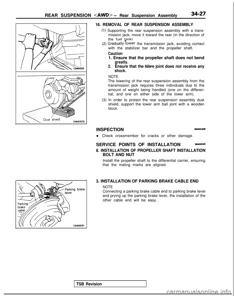
16. REMOVAL OF REAR SUSPENSION ASSEMBLY
(1) Supporting the rear suspension assembly with a trans-
mission jack, move it toward the rear (in the direction of
the fuel tank).
(2)
Graduallyibwer the transmission jack, avoiding contact
with the stabilizer bar and the propeller shaft.
Caution
1. Ensure that the propeller shaft does not bend
greatly.
2.Ensure that the liibro joint does not receive any
shock.
NOTE
The lowering of the rear suspension assembly from the
transmission jack requires three individuals due to the
amount of weight being handled (one on the differen-
tial, and one on either side of the lower arm).
(3) In order to protect the rear suspension assembly dust shield, support the lower arm ball joint with a wooden
block.
TSB Revision
INSPECTIONM24GCAM
l Check crossmember for cracks or other damage.
SERVICE POINTS OF INSTALLATION
M34GDAfl
8. INSTALLATION OF PROPELLER SHAFT INSTALLATION
BOLT AND NUT Install the propeller shaft to the differential carrier, ensuring
that the mating marks are aligned.
3. INSTALLATION OF PARKING BRAKE CABLE END
NOTE
Connecting a parking brake cable end to parking brake lever
and prying up the parking brake lever, the installation of the other cable end will be easy.