1989 MITSUBISHI GALANT steering
[x] Cancel search: steeringPage 110 of 1273
II-60ENGINE
(9) If a cylinder’s compression pressure or pressure differenceis outside the limit, fill a small amount of engine oil through
the spark plug hole and repeat Items (7) and (8) above.
@ If the compression is increased when the oil is filled, the piston
and/or cylinder wall may be worn or
damaged.
@ If the compression is not Increased even though the oil is filled, the valve may be thermally seized, the valve
contact may be improper or pressure may leak at the
gasket. (10)Connect the connector of the crankshaft position sensor.
(1l)lnstall
the spark plug and spark plug cable.
(12)Erase the diagnostic trouble code with the scan tool or re-
connect the battery (-)
cable 10 seconds or more after it
was disconnected.
NOTE
This will erase the memory of the diagnostic trouble code which resulted from disconnection of the crankshaft posi-
tion sensor connector.
MANIFOLD VACUUM INSPECTION MllFNAD
(1) Before inspection and adjustment, put the vehicle into the following state.
l Engine coolant temperature:
85-95°C (185-205°F)
l Lights, motor cooling fan, and accessories: OFF
l Transaxle:
N (Neutral)
l Steering wheel: Neutral
(2) Check that the idling revolution speed is normal.
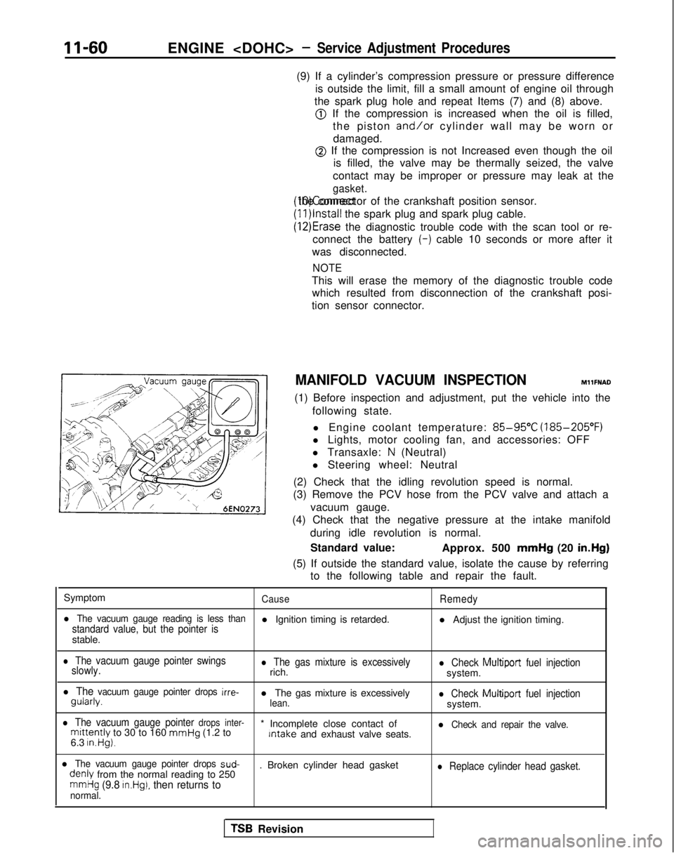
(3) Remove the PCV hose from the PCV valve and attach a
vacuum gauge.
(4) Check that the negative pressure at the intake manifold
during idle revolution is normal.
Standard value: Approx. 500 mmHg
(20 in.Hg)
(5) If outside the standard value, isolate the cause by referring to the following table and repair the fault.
Symptom
CauseRemedy
l The vacuum gauge reading is less thanstandard value, but the pointer isl Ignition timing is retarded. l Adjust the ignition timing.
stable.
l The vacuum gauge pointer swings
slowly.l The gas mixture is excessivelyrich.l Check Multiport fuel injectionsystem.
l The vacuum gauge pointer drops irre- gularly.
l The gas mixture is excessively
lean.l Check Multiport
fuel injectionsystem.
l The vacuum gauge pointer drops inter-mittently to 30 to 160 mmHg
(1.2 to * Incomplete close contact of Intake
and exhaust valve seats.l Check and repair the valve.
6.3 in.Hg).
l The vacuum gauge pointer drops sud- denly
from the normal reading to 250 . Broken cylinder head gasketl Replace cylinder head gasket.
mmHg (9.8 in.Hg), then returns tonormal.
TSB Revision
Page 111 of 1273
ENGINE
DRIVE BELTS TENSION ADJUSTMENT
MllFMBBl
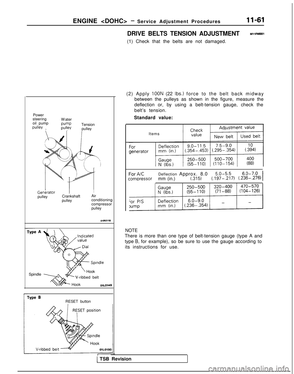
(1) Check that the belts are not damaged.
Power
steering
oil pump
pulley , W
ater
pump
pulley
Tension
pulley
f /
xI J
b
L ‘d
p1 Genkrator
I
Ipulley
Crankshaft
Air
pulley conditioning
compressor
pulley
Spindle Spindle
2Y
\Hook
xi@--
V-ribbed belt
Hook
r
Type BRESET button (2) Apply
100N (22 Ibs.) force to the belt back midwa
y
between the pulleys as shown in the figure, measure the
deflection or, by using a belt-tension gauge, check the
belt’s tension.
Standard value:
Items
For
AKDeflection Approx. 8.05.0-5.56.0-7.0
comDressormm (in.)t.3151(.197-,217) (.236-.276)I
NOTE
There is more than one type of belt-tension gauge (type A and
type
B, for example), so be sure to use the gauge according to
its instructions for use.
1 TSB Revision
Page 112 of 1273
II-62ENGINE
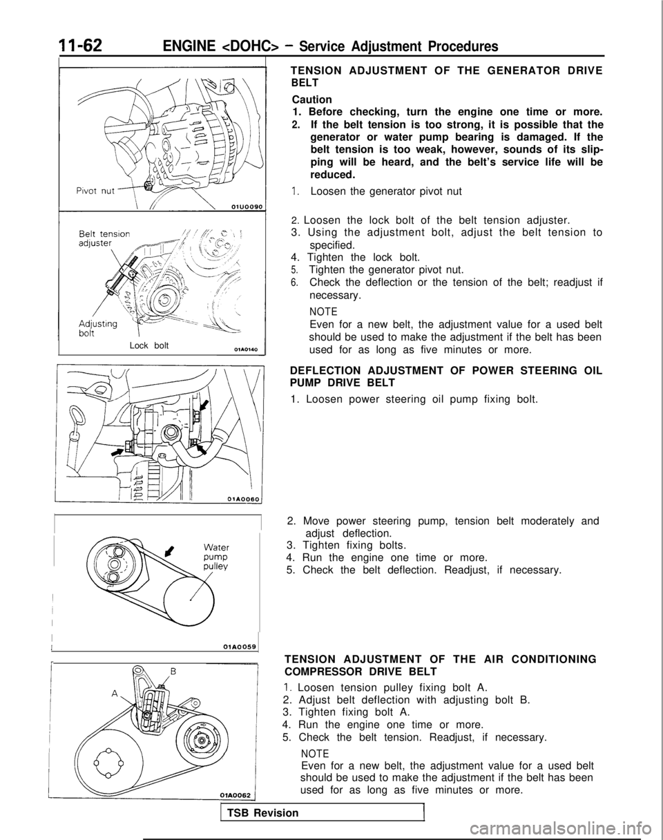
Lock boltTENSION ADJUSTMENT OF THE GENERATOR DRIVE
BELT
Caution
1. Before checking, turn the engine one time or more.
2.If the belt tension is too strong, it is possible that the
generator or water pump bearing is damaged. If the belt tension is too weak, however, sounds of its slip-
ping will be heard, and the belt’s service life will be
reduced.
1.Loosen the generator pivot nut
2. Loosen the lock bolt of the belt tension adjuster.
3. Using the adjustment bolt, adjust the belt tension to
specified.
4. Tighten the lock bolt.
5.Tighten the generator pivot nut.
6.Check the deflection or the tension of the belt; readjust if
necessary.
NOTE
Even for a new belt, the adjustment value for a used belt
should be used to make the adjustment if the belt has been used for as long as five minutes or more.
DEFLECTION ADJUSTMENT OF POWER STEERING OIL
PUMP DRIVE BELT 1. Loosen power steering oil pump fixing bolt.
2. Move power steering pump, tension belt moderately and adjust deflection.
3. Tighten fixing bolts.
4. Run the engine one time or more. 5. Check the belt deflection. Readjust, if necessary.
IIOlA0059
r
TSB Revision TENSION ADJUSTMENT OF THE AIR CONDITIONING
COMPRESSOR DRIVE BELT
1. Loosen tension pulley fixing bolt A.
2. Adjust belt deflection with adjusting bolt B.
3. Tighten fixing bolt A.
4. Run the engine one time or more. 5. Check the belt tension. Readjust, if necessary.
NOTE
Even for a new belt, the adjustment value for a used belt
should be used to make the adjustment if the belt has been
used for as long as five minutes or more.
Page 116 of 1273
11-66ENGINE
28
29
30
35-45 Nm25-33 ftlbs.
50-65 Nm36-47 ft.lbs.
I
3132
40-50
Nm29-36 ftlbs.
43-56
ft.lbs.
-- .__.. 36-47
ft.lbs.* 54’q
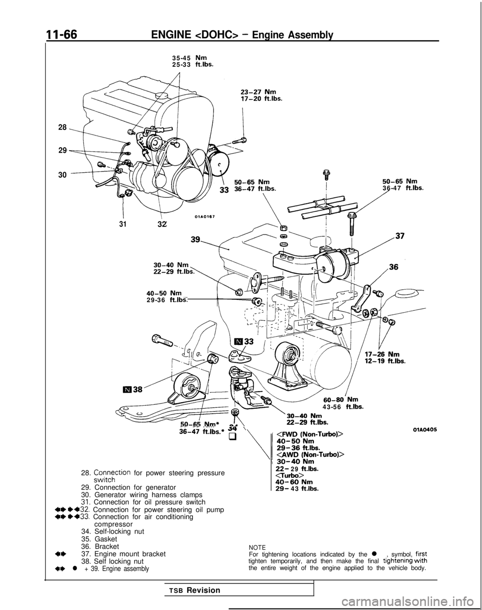
28. z;tFhction for power steering pressure
29. Connection for generator
30. Generator wiring harness clamps
31. Connection for oil pressure switch 4W 1)432.
Connection for power steering oil pump
++ ++33. Connection for air conditioning
compressor
34. Self-locking nut
35. Gasket
36. Bracket
4*37. Engine mount bracket
38. Self locking nut
+e l + 39. Engine assembly
22- 29 ftlbs.c-rurbo>40-60 Nm29- 43 ftlbs.
OlAO405
NOTEFor tightening locations indicated by the l , symbol, firsttighten temporarily, and then make the final tlghtenlng withthe entire weight of the engine applied to the vehicle body.
TSB Revision
Page 117 of 1273
ENGINE
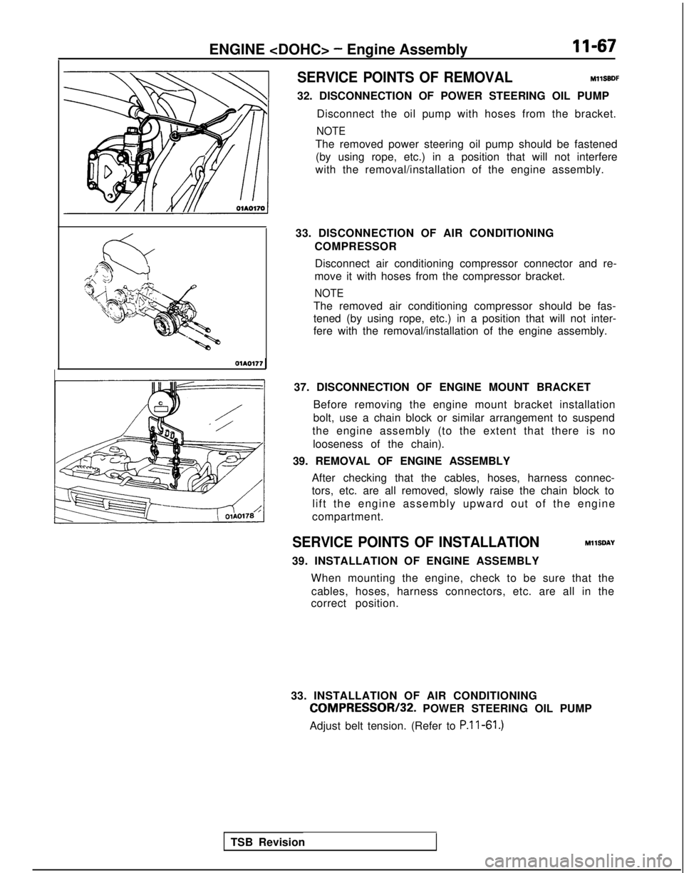
SERVICE POINTS OF REMOVAL
MllSBDF
32. DISCONNECTION OF POWER STEERING OIL PUMP Disconnect the oil pump with hoses from the bracket.
NOTE
The removed power steering oil pump should be fastened(by using rope, etc.) in a position that will not interfere
with the removal/installation of the engine assembly.
33. DISCONNECTION OF AIR CONDITIONING COMPRESSOR
Disconnect air conditioning compressor connector and re-
move it with hoses from the compressor bracket.
NOTE
The removed air conditioning compressor should be fas-
tened (by using rope, etc.) in a position that will not inter-
fere with the removal/installation of the engine assembly. OlA0177
37. DISCONNECTION OF ENGINE MOUNT BRACKETBefore removing the engine mount bracket installation
bolt, use a chain block or similar arrangement to suspend
the engine assembly (to the extent that there is no
looseness of the chain).
39. REMOVAL OF ENGINE ASSEMBLY After checking that the cables, hoses, harness connec-
tors, etc. are all removed, slowly raise the chain block tolift the engine assembly upward out of the engine
compartment.
SERVICE POINTS OF INSTALLATION MllSDAY
39. INSTALLATION OF ENGINE ASSEMBLY When mounting the engine, check to be sure that thecables, hoses, harness connectors, etc. are all in the
correct position.
33. INSTALLATION OF AIR CONDITIONING
COMPRESSOR/32. POWER STEERING OIL PUMP
Adjust belt tension. (Refer to P.l l-61.)
TSB Revision
Page 130 of 1273
II-80ENGINE
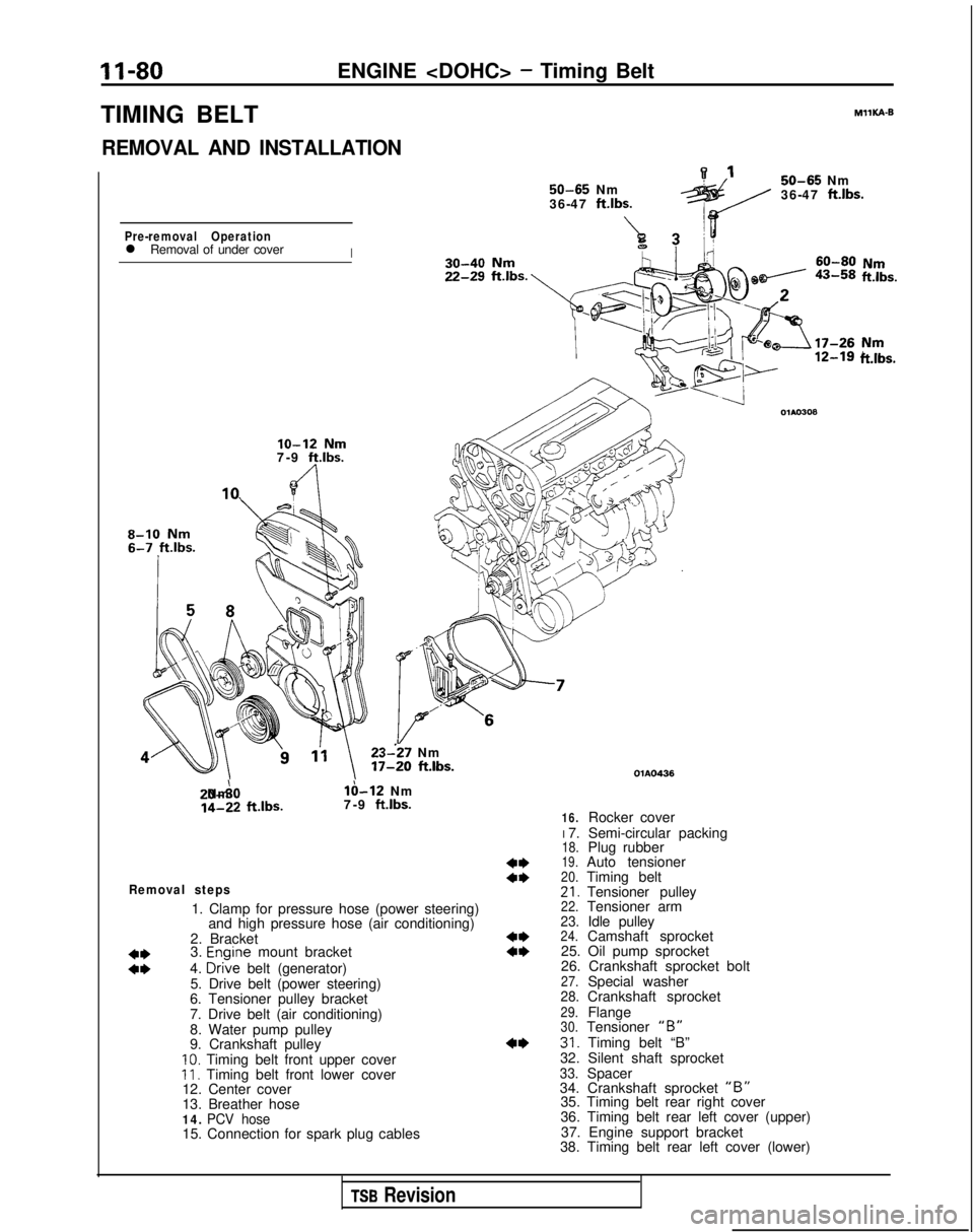
TIMING BELT
REMOVAL AND INSTALLATION 50-65
Nm
36-47 ftlbs.
A7Pre-removal Operationl Removal of under coverI MIlKA-B
50-65
Nm
36-47
ft.lbs.
ii!&.
lo-12 Nm7-9 ft.lbs.
8-10 Nm
23--27 Nm 17-20
ft.lbs. 20-A0 Nm
lb-12 Nm
14-22
ftlbs.
7-9 ft.lbs.
Removal steps
1. Clamp for pressure hose (power steering)
and high pressure hose (air conditioning)
2. Bracket
3.
Enoine mount bracket
ii4. D&e belt (generator)
5. Drive belt (power steering)
6. Tensioner pulley bracket
7. Drive belt (air conditioning)
8. Water pump pulley
9. Crankshaft pulley
10. Timing belt front upper coverII. Timing belt front lower cover
12. Center cover
13. Breather hose
14. PCV hose15. Connection for spark plug cables
ft.lbs.
4*a*
4**I)
4* OlAO436
16.Rocker cover
I 7. Semi-circular packing
18.Plug rubber19.Auto tensioner20.Timing belt21.Tensioner pulley22.Tensioner arm23.Idle pulley24.Camshaft sprocket
25. Oil pump sprocket
26. Crankshaft sprocket bolt
27.Special washer28.Crankshaft sprocket29.Flange30.Tensioner “B”31. Timing belt “B”
32. Silent shaft sprocket
33.Spacer
34. Crankshaft sprocket “B”35. Timing belt rear right cover
36. Timing belt rear left cover (upper)
37. Engine support bracket
38. Timing belt rear left cover (lower)
TSB Revision
Page 131 of 1273
ENGINE
f”.53A51b;m
r----v 1
3
lo-12 Nm
11-16
ftlbs.80-100
Nm y~x-di
58-72ft.lbs.2234!?!I
212543-55Nm 31-40, ff.lbs.b&-.,\‘-
/20-27 Nm
14-20
ftlbs.110;130 Nm80-94
ftlbs.
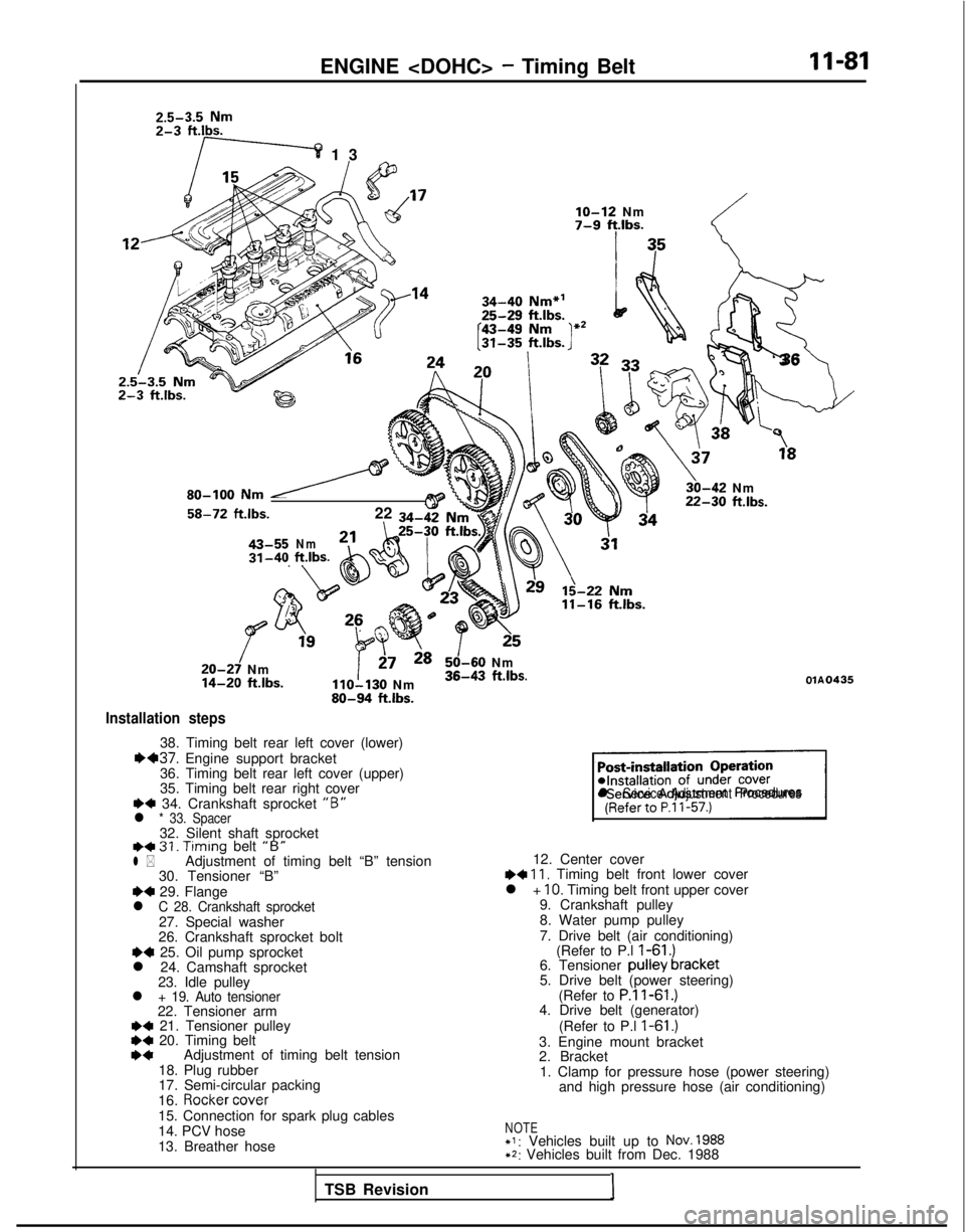
Installation steps
38. Timing belt rear left cover (lower)1H37. Engine support bracket
36. Timing belt rear left cover (upper)
35. Timing belt rear right cover
+4 34. Crankshaft sprocket “B”l * 33. Spacer32. Silent shaft sprocketI)+ 31. Timing
belt “B”l *Adjustment of timing belt “B” tension
30. Tensioner “B”
~~ 29. Flangel C 28. Crankshaft sprocket27. Special washer
26. Crankshaft sprocket bolt
~~ 25. Oil pump sprocket
l 24. Camshaft sprocket 23. Idle pulley
l + 19. Auto tensioner22. Tensioner arm+a 21. Tensioner pulley*C 20. Timing beltI)*Adjustment of timing belt tension
18. Plug rubber
17. Semi-circular packing
16.
Rocker cover
15. Connection for spark plug cables
14. PCV hose
13. Breather hose
!_-;
‘3
6
\
3,“”
30-42 Nm22-30 ftlbs.
125
50-60 Nm36-43 ftlbs.OlA0435
sl Service Adjustment Procedures
12. Center cover~~ 11, Timing belt front lower cover
l + IO. Timing belt front upper cover
9. Crankshaft pulley
8. Water pump pulley
7. Drive belt (air conditioning) (Refer to P.l
I-61 .)6. Tensioner pulley bracket
5. Drive belt (power steering)
(Refer to
P.ll-61.)4. Drive belt (generator)
(Refer to P.l
I-61 .)3. Engine mount bracket
2. Bracket1. Clamp for pressure hose (power steering) and high pressure hose (air conditioning)
NOTE+I: Vehicles built up to NOV. 1988+2: Vehicles built from Dec. 1988
TSB Revision I
Page 143 of 1273
13-1
FUEL
CONTENTSM’ISAA--
AUTO-CRUISE CONTROL SYSTEM.............
.
332
AUTO-CRUISE CONTROL ............................. 408
SERVICE ADJUSTMENT PROCEDURES .................397
Accelerator Cables
inspectron and Adjustment ........
.
398 Auto-cruise
Control System Inspection
..............397
Individual Parts Inspection ......................
401SPECfAL
TOOLS
.....................................
333
SPECIFICATIONS .................................... 332
TROUBLESHOOTING ................................. 334
Auto-cruise Control Components Location ..........368
Auto-cruise Control
Related Harnesses
..........365
Check Chart
Check Chart
Circuit Diagram ................................
371input Checking................................
.
366
On-board Diagnostic Checking ......................
361Troubleshooting Quick-reference Chart
.
334
Troubleshooting Quick-reference Chart
ENGINE CONTROL...............................
.
328
ENGINE CONTROL ..................................
330
SERVICE ADJUSTMENT PROCEDURES .................329
Accelerator Cable inspectron and Adjustment
...........329
Accelerator Switch Inspection and Adjustment ..........329
SPECIFICATIONS ....................................
328
TROUBLESHOOTlNG................................
.
328
Accelerator
Cable and Accelerator Pedal .............
.
328
FUEL SYSTEM
FUEL FILTER .........................................
327
FUEL LINE AND VAPOR LINE
.
326
FUEL LINE AND VAPOR LINE
.
324
FUEL TANK
.
322
FUELTANK
.
318
GENERAL INFORMATION ............................ 196
ON-VEHICLE INSPECTION OF MFI
COMPONENTS
......251
Air Conditioning Switch and A/C Compressor Clutch Relay .....................................
285
Barometric Pressure Sensor .................... 266
Boost Meter
311Camshaft Position Sensor ........................
.
277Closed Throttle Position Switch
.....................
.
274
Component Location .............................
251Components Inspection Pocedure
................. 255
Crankshaft Position Sensor ..................... 280EGR
Solenord
...................
.
307EGR Temperature Sensor
.............
.
288Engrne Control Module Power Ground
................
.
257
Engine Coolant Temperature Sensor ..................
268Evaporative Emission Purge Solenoid .................
.
307
Fuel Pressure Solenoid
307Fuel Pressure Test...............................
.
312
Fuel Pump ...................................... 258
Heated Oxygen Sensor ............................ 290
Idle Air Control Motor (Stepper Motor) ................
238Ignition Coil and Ignition Power Transistor .............
.
302
Ignition Switch-ST .................................. 284
Ignition Switch-ST and Park/Neutral Position Switch .....284
Injectors .......................................
295Inspection of Engine Control Module Terminal
Voltage .......................................
.
315
Intake Air Temperature Sensor .......................263
Knock Sensor
Power Steering Pressure Switch ......................
284Power Supply and Ignition Switch ...................
.
255Resistor
..............................
.
298Terminal Voltage Check Chart
......................
.
315Throttle Position Sensor
..........................
.
270Turbocharger Waste Gate Solenoid
.........
.
309 Vehicle
Speed Sensor
............................... 284
Volume Air Flow Sensor ............................
261SERVICE ADJUSTMENT PROCEDURES ...............
.
245
Basic
idle Speed Adjustment .......................
.
245
Closed Throttle Position Switch (Fixed
SAS)Adjustment ......................................
.
250
Curb
Idle Speed Inspection
..........................245Throttle Body (Throttle Valve Area) Cleaning
...........
.
248Throttle Position Sensor Adjustment
..................
.
248
SPECIALTOOLS...................................
.
204
SPECIFICATIONS ...................................
201TROUBLESHOOTING ...............................
.
205
Check Engine/Malfunction Indicator Lamp ..............205
Circuit Diagram .................................... 214
Clear Memory of Diagnostic Trouble Code .............
211Explanation and Precaution Related to Harness
Checking ......................................
.
205Explanation of Troubleshooting Procedures
............
.
205Failsafe/Back-up Functions List
.....................
.
211Fuel tank and Fuel Line
............................
.
244
Read Out Diagnostic Trouble Code ...................
211Troubleshooting Table
.............................
.
208(CONTINUED ON NEXT PAGE)